DESIGN AND ANALYSIS OF A LIGHTWEIGHT CHASSIS FOR HUMAN POWERED VEHICLE
SABRI ADLAN BIN ZAINOL
DESIGN AND ANALYSIS OF A LIGHTWEIGHT CHASSIS FOR HUMAN POWERED VEHICLE
SABRI ADLAN BIN ZAINOL
This report is submitted
in fulfillment of the requirement for the degree of Bachelor of Mechanical Engineering (Automotive)
Faculty of Mechanical Engineering
UNIVERSITI TEKNIKAL MALAYSIA MELAKA
ii
DECLARATION
I declare that this project report entitled “Design and Analysis of a Lightweight Chassis for Human Powered Vehicle” is the result of my own work except as cited in the references
Signature : ...
Name : Sabri Adlan Bin Zainol
iii APPROVAL
I hereby declare that I have read this project report and in my opinion this report is sufficient in terms of scope and quality for the award of the degree of Bachelor of Mechanical Engineering (Automotive).
Signature :………..
iv
DEDICATION
v ABSTRACT
vi ABSTRAK
Kenderaan bertenaga manusia (HPV) adalah sebuah kenderaan yang menggunakan kekuatan fizikal dan otot badan manusia. Kebiasaannya, HPV mempunyai berat di antara 30 kg hingga 50 kg, di mana ia adalah agak berat untuk perlumbaan dan kegunaan rekreasi. Oleh itu, kebanyakkan HPV mempunyai kesukaran dan memerlukan tenaga yang lebih untuk bergerak. Ini disebabkan rangka HPV tersebut yang sangat berat. Sehubungan itu, tesis ini mensasarkan reka bentuk rangka HPV yang ringan beserta kekukuhan yang terbaik melalui analisis pecutan dan belokan. Pemilihan reka bentuk dan bahan untuk rangka HPV adalah sangat penting untuk mendapatkan HPV yang kuat, ringan dan tegar. Terdapat empat reka bentuk yang
berlainan saiz struktur besi yang akan diuji menggunakan ‘Finite Element Analysis’
(FEA) dalam perisian ANSYS Workbench. Selain itu, tiga bahan berlainan akan
digunakan dalam setiap reka bentuk untuk setiap analisis. Analisis tersebut merangkumi analisis pecutan, belokan dan pusingan di mana ianya adalah dalam keadaan statik. Seterusnya, analisis diteruskan dengan mengenakan daya dan sokongan kekal pada bahagian tertentu pada rangka HPV. Daya yang kenakan mewakili berat pemandu dan ianya dikenakan di pusat rangka di mana tempat untuk pemandu tersebut akan duduk. Manakala, sokongan kekal dikenakan pada semua tempat yang mempunyai tayar. Daripada analisis tersebut, perisian ANSYS Workbench akan mengeluarkan hasil jumlah pesongan, jisim, tekanan Von-mises dan faktor keselamatan. Selepas itu, beberapa kiraan akan dilakukan untuk mencari kadar kekerasan bengkokan dan kadar kekerasan pusingan yang terbaik. Seterusnya, rekabentuk yang mempunyai jisim yang terbaik akan diuji tahap faktor keselamatannya supaya berada dalam keadaan yang sesuai dan selamat. Kemudian, tekanan Von-mises akan dibandingkan dengan tekanan kekuatan bahan tersebut untuk menentukan kekuatan rangka kenderaan. Selepas itu, hasil keputusan akan dibandingkan dengan penanda aras daripada hasil kajian atau sumber lain untuk mencapai objektif kajian. Akhir sekali, rekabentuk rangka yang ringan, lebih keras
dan mempunyai ciri-ciri keselamatan terbaik akan dipilih berdasarkan ‘weight
vii
ACKNOWLEDGEMENTS
First of all, gratefulness of thanks to our Creator, “Allah” for His continuous blessing, which make this work become easier and can be completed in time.
Secondly, I would like to express my deepest appreciation to those who have provided me the encouragement to complete this Final Year Project Report. A special thank goes to my project supervisor, Associate Professor Dr. Mohd Azman Bin Abdullah for his contribution, guidance, critics and comments during my progress in completing this project. His professional views and valuable opinions allow me to make the appropriate solutions on the problems that I had encountered during the most critical stages of my work. The knowledge and tips given are valuable to my future career.
viii
TABLE OF CONTENT
CHAPTER TOPIC PAGE
DECLARATION ii
APPROVAL iii
DEDICATION iv
ABSTRACT v
ABSTRAK vi
ACKNOWLEDGEMENTS vii
TABLE OF CONTENT viii
LIST OF FIGURES x
LIST OF TABLES xiv
LIST OF ABBREVIATIONS xv
LIST OF SYMBOLS xvi
1 INTRODUCTION 1
1.1 Background 1
1.2 Problem Statement 3
1.3 Objectives 3
1.4 Scope of Project 3
2 LITERATURE REVIEW 4
2.1 Introduction 4
2.2 Human Powered Vehicle 4
2.3 Frame 6
2.4 Chassis 7
2.5 Ladder Chassis 7
2.6 Backbone Chassis 8
ix
2.8 Monocoque Chassis 10
2.9 Materials 11
2.10 Finite Element Analysis of ANSYS Software 15
3 METHODOLOGY 16
3.1 Introduction 16
3.2 Flow Chart of Project Methodology 17
3.3 Benchmarking 18
3.4 Conceptual Design 3.5 Analysis
19 21
4 RESULTS AND DISCUSSION 32
4.1 ANSYS Analysis Results 32
4.2 Bending and Torsional Stiffness 42
4.3 Safety Factor 49
4.4 Weight Decision Matrix 61
4.5 Discussion 65
5 CONCLUSION AND FUTURE WORK 71
5.1 Conclusion 71
5.2 Future Work 72
REFERENCES 74
x
LIST OF FIGURES
FIGURE TITLE PAGE
1.1 Frame structured in HPV (Das, 2013). 1
2.1(a) Aerodynamic shell HPV. 5
2.1(b) Structural frame HPV. 5
2.2 Body measurement parameters (Allen et al., 2015). 6
2.3 Model of ladder chassis (Singh et al., 2014). 8
2.4 Model of backbone chassis (Ludd, 2013). 9
2.5 Model of space frame chassis (Das, 2013). 10
2.6 Model of monocoque chassis (Carello et al., 2014). 11
3.1 Flow chart of the methodology. 17
3.2 Sketched conceptual design. 20
3.3 CAD model of final design. 20
3.4 Rendering model of final design. 21
3.5 Idealization of the chassis using line element. 23
3.6 Model visualization with cross-sections. 23
3.7 L-shaped cross-sectional beam. 24
3.8 Circular cross-sectional beam. 24
xi
3.10 Computational model featuring elements. 25
3.11 Computational model featuring constraints for torsional
analysis.
26
3.12 Computational model featuring loads for torsional analysis. 27
3.13 Computational model featuring fixed support for bending
loads analysis.
28
3.14 Computational model featuring downwards loads. 29
3.15 Computational model featuring front loads for acceleration
analysis.
29
3.16 Computational model featuring side loads for cornering
analysis.
30
4.1 Fourth design of aluminium alloy chassis for cornering
analysis.
33
4.2 Fourth design of structural steel chassis for cornering
analysis.
34
4.3 Fourth design of stainless steel chassis for cornering analysis. 34
4.4 Total deformation for cornering analysis. 35
4.5 Fourth design of aluminum alloy chassis for acceleration
analysis.
36
4.6 Fourth design of structural steel chassis for acceleration
analysis.
37
4.7 Fourth design of stainless steel chassis for acceleration
analysis.
37
xii
4.9 Fourth design of aluminum alloy chassis for torsional
analysis.
39
4.10 Fourth design of structural steel chassis for torsional analysis. 40
4.11 Fourth design of stainless steel chassis for torsional analysis. 40
4.12 Total deformation for torsional analysis. 41
4.13 Bending stiffness for cornering analysis. 44
4.14 Bending stiffness for acceleration analysis. 45
4.15 Free body diagram of the chassis structure with respect to
frontal view.
46
4.16 Overall torsional stiffness analysis. 47
4.17 Overall mass of the chassis design. 48
4.18 Von-mises stress of structural steel chassis for cornering
analysis.
50
4.19 Safety factor of structural steel chassis for cornering analysis. 51
4.20 Von-mises stress of stainless steel chassis for cornering
analysis. 51
4.21 Safety factor of stainless steel chassis for cornering analysis. 52
4.22 Von-mises stress of aluminium alloy chassis for cornering
analysis.
52
4.23 Safety factor of aluminium chassis for cornering analysis. 53
4.24 Von-mises stress of structural steel chassis for acceleration
analysis.
54
4.25 Safety factor of structural steel chassis for acceleration
analysis.
xiii
4.26 Von-mises stress of stainless steel chassis for acceleration
analysis.
55
4.27 Safety factor of stainless steel chassis for acceleration
analysis.
55
4.28 Von-mises stress of aluminium alloy chassis for acceleration
analysis.
56
4.29 Safety factor of aluminum alloy chassis for acceleration
analysis.
56
4.30 Von-mises stress of structural steel chassis for torsional
analysis.
57
4.31 Safety factor of structural steel chassis for torsional analysis. 58
4.32 Von-mises stress of stainless steel chassis for torsional
analysis.
58
4.33 Safety factor of stainless steel chassis for torsional analysis. 59
4.34 Von-mises stress of aluminum alloy chassis for torsional
analysis.
59
xiv
LIST OF TABLES
TABLE TITLE PAGE
2.1 Material properties (Prajwal et al., 2014). 11
2.2 Material properties for typically used frame design materials
(Porter et al., 2014).
13
2.3 Comparison of material properties (Kamaruddin et al., 2016). 14
3.1 Overall geometries of cross-sectional beams. 31
4.1 Overall total deformation for cornering analysis. 35
4.2 Overall total deformation for acceleration analysis. 38
4.3 Overall total deformation for torsional analysis. 41
4.4 Overall bending stiffness for cornering analysis. 43
4.5 Overall bending stiffness for acceleration analysis. 45
4.6 Overall torsional stiffness. 46
4.7 Overall mass of the chassis design. 47
4.8 Yield strength and ultimate strength from ANSYS
Workbench.
49
4.9 Overall Von-Mises stress and safety factor. 60
4.10 Decision matrix for overall mass of the chassis designs. 62
xv
LIST OF ABBREVIATIONS
HPV Human Powered Vehicle
FEA Finite Element Analysis
TIG Tungsten Inert Gas
GPU Graphic Processing Units
3D 3-Dimensional
CAD Computer Aided Design
xvi
LIST OF SYMBOLS
K = Stiffness (N/m)
F = Force (N)
δ = Deformation (m)
Mt = Twisting Moment (Nm)
θ = Angle of rotation (rad)
1
CHAPTER 1
INTRODUCTION
1.1 BACKGROUND
There are many types of pollution occurred on earth such as water pollution, thermal pollution, noise pollution and air pollution. Air pollution can be considered
as one of the main hazards to the health of human being. The air pollutionis due to
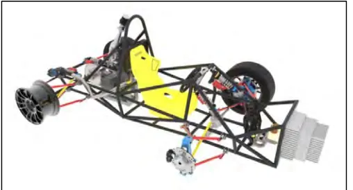
the increasing number of vehicles used by human that also contribute to global warming. Many incentives have been made to solve these problems. One of the efforts is a Human Powered Vehicle (HPV) creation, which can be popularized as a viable form of green technology and sustainable transportation. This transportation is powered only by muscular-strength (Abdullah et al., 2016). HPV systems consist of many main components sub-system such as drivetrain system, steering system, brake system, chassis and tires. This project will cover the chassis sub-system. There are three chassis structures in a passenger car namely frame, underbody and sub-frame
structures. However, most HPV design used the frame structure as shown in Figure
1.1.
[image:18.595.210.464.609.746.2]
2
Supposedly, chassis supports the HPV components and payload mounted upon it including all the sub-systems mentioned earlier (Kumar & Deepanjali, 2008). When the HPV travel along the road, its chassis is subjected to a stress, bending moment and vibration induced by road roughness. Stress that acting on the chassis varies with the displacement and each part of the chassis. Because of the behavior of the chassis that is always subjected to a stress, a weak structurally designed part will collapse. Therefore, there are factors that need to be considered in this project in order to produce a strong and lightweight chassis. The factors are mass, bending and torsional stiffness (Galolia & Patel, 2011), total deformation and Von-mises stress.
For the weight of the HPV, there are four elements or characteristics that need to be considered which are material, parameter of frame structure, shape of frame structure, and design of the chassis. These elements will affect the mass of the chassis in order to get a lightweight chassis. As for the toughness of the chassis, those elements also play an important role to produce the value of bending and torsional stiffness, total deformation and Von-mises stress in static analysis. Static analysis will determine displacement, stress or component that do not cause significant damping effect and inertia (Anurag et al., 2016). The Von-mises stress is used by engineers and designers to check whether their design can withstand the applied loads or not. When the value of Von-mises stress in particular material is higher than the yield stress of the material, the design is considered failed.
3 1.2 PROBLEM STATEMENT
The Faculty of Mechanical Engineering of Universiti Teknikal Malaysia Melaka has organized a competition for engineering students themed “Human Powered Vehicle Competition.” Although the design of HPV is important for this competition, speed must also be given major priority because the competition is a race event. One of the main problems for the design is the weight of the HPV. The HPV is having difficulties to speed up because the chassis is too heavy. Some efforts must be put to decrease the weight of the HPV. A lightweight HPV may increase the speed of the HPV and probably win the competition. Thus, the chassis, which represent the major sub-system of the HPV, must be lightweight. The selection of material and the design of the chassis are therefore crucial to ensure that the HPV is strong, lightweight and rigid.
1.3 OBJECTIVES
The objectives of this project are as follows:
a) To design a lightweight chassis with ideal stiffness through acceleration and
cornering analysis.
b) To select the best chassis through weight decision matrix analysis.
1.4 SCOPE OF PROJECT
The scope of this project are:
a) The design of chassis is based on static analysis with acceleration and cornering
condition in finding total deformation, mass, bending and torsional stiffness and lastly, maximum Von-mises stress.
b) The selection of the best analysis with various material, dimension and size of
4
CHAPTER 2
LITERATURE REVIEW
2.1 INTRODUCTION
This chapter discusses previous research and sources collected to find related information regarding this project. The sources include journals, articles, reports, Internet, books and web sites. The main purpose of this chapter is to convey the knowledge and ideas from other researchers as a guideline to complete this project. The information obtained is selected based on the objectives of the project. For example, the information about chassis frame, materials, stiffness and factor of safety are required to achieve the objectives.
This chapter is organized as follows. The next section covers human powered vehicle. Section 2.3 continues with the discussion of the frame while Section 2.4 describes the chassis. Section 2.5, 2.6, 2.7 and 2.8 explain ladder chassis, backbone chassis, space frame chassis and monocoque chassis, respectively. Section 2.9 looks into materials. Finally, Section 2.10 examines Finite Element Analysis of ANSYS Software.
2.2 HUMAN POWERED VEHICLE
5
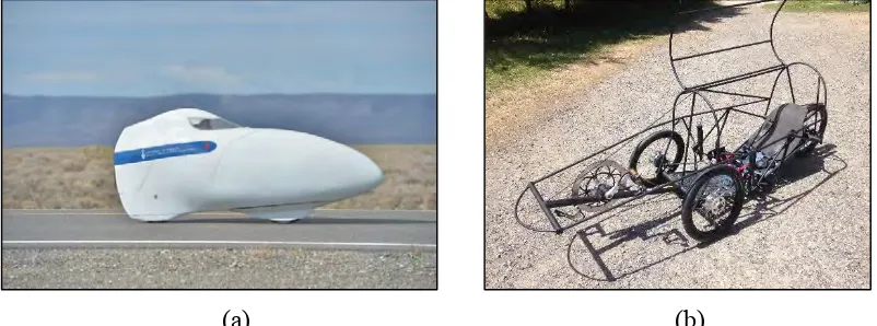
& Wilson, 1995). For land HPV, traditionally it consists of two parts structure which are aerodynamic shell called a fairing or recumbent, and the structural frame as
shown in Figure 2.1(a) and Figure 2.1(b) respectively, that supports the rider and
other vehicle systems. These two components can be combined or separated. However, both structures must be presented in some form for a vehicle to be considered as a HPV (Allen et al., 2015). HPV also vary widely in design, shape, size and scope, but the fundamental ideas behind each vehicle remains the same. That is to apply human power and energy efficiently to create a viable form of sustainable transportation.
In this era, human power is one of important criteria for local distance and long distance transportation, thus civilizations decided to use the human power in the most effective way. Human power has been researched in many different capacities, although none so significantly as upright bicycling. Bicycle is almost unique among human-powered machines in that it uses human muscles in a near-optimum way (Wilson, 2004). From the beginning to modern day of bicycles and skateboards, human power has been a cheap mode but relatively ineffective mode of transportation for long distance travel. Hence, modern transportation of long distance travel is no longer dominated by human power. However, HPV offers a viable alternative to automobiles for recreation and commuting purposes. Therefore, it serves specific purposes and ease of human life to seek comfortable yet affordable short distance mode of transportation.
(a) (b)
[image:22.595.120.521.548.697.2]6 2.3 FRAME
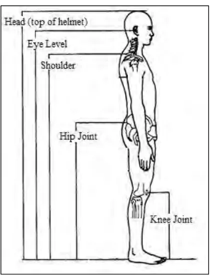
There are several choices in term of frame geometry in the design space defined by the conventional, forward-facing, recumbent rider position. For all this time, this rider position is the most mainstream design in use today for good reason as it eases the riding and optimizes rider’s comfort. However, many of HPV designs are not considering the effects on the rider’s comfort and cycling effectiveness when the rider seating position was impunity chosen. Plus, the seating position is not confirmed for which it will relate to maximum power output or not (Lei et al., 1993). Some of criteria used for comparisons are aerodynamics of frontal area, ergonomics and rider comfort, stability, experience with frame type and innovation of frame geometry (Darvirris et al., 2009). Besides that, fit and ergonomics have huge impacts on power and confidence of the rider especially on a new racer. Thus, it is crucial that each of the team’s riders can pedal effectively and achieve their full capabilities
without any obstacle. Body measurement parameters as shown in Figure 2.2 are
[image:23.595.214.424.418.692.2]becoming important criteria in designing a HPV.
7 2.4 CHASSIS
A vehicle without body is called chassis. Chassis was initially used to indicate the frame parts or basic structure of a vehicle. It is the structural backbone of any vehicle. The main function of the chassis frame is to withstand the body, parts and components, and payload placed upon it. The chassis has to detain the stresses developed, deformation, shock, twist vibration and other stresses (Francis et al., 2014). Chassis is also a skeletal frame that possesses some mechanical parts such as engine, tires, axle, assemblies, brake and steering joined together. It is the most crucial element that gives strength and stability to the vehicle under different conditions which keep the automobile rigid, stiff and unbending. Usually, it is made of a steel frame. There are four major types of chassis frames viz. ladder chassis, backbone chassis, space frame chassis and monocoque chassis (Gadagottu & Mallikarjun, 2015). Each type is explained in the subsequent section.
2.5 LADDER CHASSIS
Ladder chassis frame is one of the oldest forms of automotive chassis. As its
name connotes, ladder chassis as shown in Figure 2.3 resembles a shape of a ladder