Faculty of Engineering and Surveying
An Autonomous Bird Deterrent System
A dissertation submitted by
Timothy Lewis Clarke
in fulfilment of the requirements of
Course ENG4111 and 4112 Research Project
towards the degree of
Bachelor of Engineering (Mechatronic)
The need for an effective bird deterrent is important in many of today's industries. In the past there have been many attempts to develop a successful system with few achieving adequate results. The aim of this project was to develop and design an autonomous system that creates minimal disturbance whilst being effective in bird deterrence.
An initial investigation and evaluation into the current types of bird deterrent systems was performed and from this the method of deterrence for the designed system was selected. Once the conceptual design was completed the mechanical, electrical and software sections of the system were designed in detail and partially constructed to discover the effectiveness of the system.
During the initial implementation of the system, expected and unexpected problems in the design arose that needed dealt with. The encountered problems were then listed in each of there relative sections and supplied with solutions and suggestions for a design revision.
I certify that the ideas, designs and experimental work, results, analyses and conclusions set out in the dissertation are entirely my own effort, except where otherwise indicated and acknowledged.
I further certify that the work is original and has not been previously submitted for assessment in any other course or institution, except where specifically stated.
Timothy Lewis Clarke Student Number: Q1121485
____________________________ Signature ____________________________
I would like to extend my thanks to supervisor, Mr Chris Snook, for his support and guidance throughout the entire project process. Thank you to the electronics work shop for their guidance and help in acquiring parts and for letting me gain access to the laboratory which was greatly appreciated.
Thank you to Richard Sulman of Biosystems Engineering for your support and assistance in design. Finally I would like to thank Mark Dunn for supplying me with support during programming and his valuable time.
TIMOTHY LEWIS CLARKE
University of Southern Queensland
Abstract i
Acknowledgments iii
List of Figures x
List of Tables xii
Chapter 1 Introduction 1
1.1 Objectives 1
1.2 Background 2
Chapter 2 Bird Deterrent Systems 4 2.1 Visual Systems 4
2.1.1 Scarecrows 4
2.1.2 Corpses 6
2.1.3 Kites 6
2.2.2 Ultrasonic Devices 9
2.3 Light Systems 10
2.3.1 Strobe Lights 10
2.3.2 Lasers 11
2.4 Chemical Systems 13
2.4.1 Taste Repellents 13
2.4.2 Tactile Repellents 14
2.5 Structural Systems 15
2.5.1 Wires 15
2.5.2 Spikes 15
2.5.3 Electric Track 16
2.6 Hybrid Systems 17
2.6.1 Gas Cannons 17
2.6.2 Other Devices 18
2.7 Evaluation of Current Bird Deterrent Systems 19
2.7.1 Method of Evaluation 19
[image:7.595.147.449.32.787.2]Chapter 3 Machine Vision 24
3.1 Image Acquisition 24
3.1.1 Single Point Sensing 24
3.1.2 Line Scan Devices 26
3.1.3 Frame Scan Devices 27
3.2 Basic Image Processing 28
3.3 Applications of Machine Vision 31
3.3.1 General Applications 31
3.3.2 Case Study 32
3.4 Vision Applications in Bird Deterrence 34
Chapter 4 Mechanical Design 35 4.1 Conceptual Design and Requirements 35
4.2 Material Selection 37
4.3 H-Bridge 38
4.3.1 Transistor Driven 40
4.3.2 Commercial Packages 41
4.4.2 DC Motors 43
4.5 Electrical Schematic 45
4.6 Final Design and Construction 47
4.6.1 Base 47
4.6.2 Gearing 48
4.6.3 Disc 50
4.6.4 Camera Mount 51
4.6.5 Electrical Circuits 52
4.6.6 Final Design Overview 53
Chapter 5 Software Design 54 5.1 Requirements and Specifications 54
5.2 Programming Language Selection 55
5.3 Program Flow Chart 55
5.4 Image Analysis 57
5.5 Graphical User Interface 59
5.5.3 Information Presentation 60
5.5.4 GUI Features 61
5.6 System Overview 62
5.6.1 Mechanical Test Routine 62
5.6.2 Limit Test Routine 63
5.6.3 General Operation 63
Chapter 6 Improvements and Further Work 65 6.1 Introduction 65
6.2 Mechanical Design 66
6.2.1 Base Rotation 66
6.2.2 Limits and Feedback 67
6.3 Electrical Design 68
6.4 Software Design 69
6.5 Deterrent Application and Testing 70
6.6 Further Project Work 73
References 74
B.1 General Program 80
Appendix C Component Data Sheets 83 C.1 BUZ171 84
C.2 2SJ349 85
C.3 BC549 86
C.4 20NE06 86
C.5 L298 88
Appendix D Detailed Drawings 89 D.1 Base 90
D.2 Camera 91
D.3 Camera Mount 92
D.4 Disc 93
D.5 H-Bridge 94
D.6 Motor 95
D.7 Upright 96
1.2.1 Bird Impact on Light Aircraft 3
2.1.1 Rotating Scarecrow (Scaring Birds Website) 5
2.1.2 Scarey Man (Clarratts Website) 5
2.2.1 Bird Chaser (www.pest- control.biz ) 8
2.2.2 Bird Chase Ultrasonic (BirdBGone Website) 9
2.3.1 Bird Lite (Critter Ridders Website) 10
2.3.2 Avian Dissuader (SEATech Website) 12
2.3.3 Prototype Rotating Laser (SEATech Website) 12
2.4.1 Hot Foot Repellent Gel (Hot Foot Website) 14
2.5.1 Bird Spike 2001 (BirdBGone Website) 16
2.6.1 Propane Gas Cannon (BirdBlaster Website) 17
2.6.2 The Scarecrow (BirdBGone Website) 18
2.7.1 Directional Strobe Light 23
3.1.1 Optical LED and Sensor (Howstuffworks Website) 25
3.1.2 Line Scanned Image 26
3.1.3 Digitised Gray Scale Image (Source Unknown) 27
3.2.3 Angle of Orientation (Fisher, Perkins, Walker, Wolfart) 30
3.2.4 Example of Hough Transform (Strzodka, 2003) 30
3.3.1 Sample Screens for Observation (Matthews, 2003) 33
3.4.1 Edge detection showing movement in top left segment 34
4.1.1 Conceptual Design 35
4.1.2 DC Motor and Gears 36
4.3.1 Basic H-Bridge (Brown, 1998) 38
4.3.2 Forward Current Flow (Brown 1998) 39
4.3.3 Transistor Driven H-Bridge (Brown 1998) 40
4.3.4 Sample L298 Configuration (ST Electronics) 41
4.4.1 Stepper Motor Full Steps (Haydon Website) 42
4.4.2 DC Motor (Howstuffworks Website) 44
4.5.1 Overall Electrical Schematic 45
4.5.2 H-Bridge Detailed Design 46
4.5.3 Limit Switch Connection 46
4.6.1 Tamiya Universal Gearbox (Tamiya, Inc.) 48
4.6.2 Gear and Chain Configuration 49
4.6.3 Disc Construction 50
4.6.4 Camera Mount 51
4.6.5 Bread Board Circuit 52
5.3.1 Program Flow Chart 56
5.4.1 Image Comparison 58
5.5.1 GUI Design 61
2.1 Evaluation of Bird Deterrent Systems 21
Chapter 1
Introduction
1.1
Objectives
1.2
Background
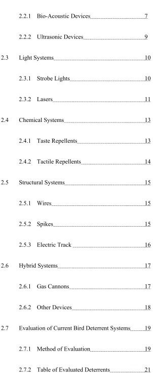
Birds cause more damage to produce farms and orchards than any other creature. Each year birds destroy crops and cause farmers significant economic damage. Studies conducted at the New Zealand Plant Protection Society (Coleman & Spurr 2001) show that 87% of farmers surveyed had encountered crop damage from birds that was significant enough to be considered a problem. The extent of the damage in some of these cases was equal to 20% of the farmers total harvest for that year which led to large economic blows.
Coghlan (1990, vol.128, p. 48) in his article Pigeons, Pests and People refers to birds as “rats with wings” for the speed of which they can affect an area and transmit diseased spores through their excrements. Diseases such as AIDS, Toxoplasmosis, Listeriosis, Viral Meningitis, Encephalitis, Salmonella and Paratyphoid are readily spread in places of high pigeon population due to the amount of droppings produced. Along with the disease that they bring the aesthetic value of buildings is lowered by large amounts of bird habitation due to the amount of droppings and the added noise made during the early hours of the morning.
on the development of a successful bird deterrent system to ensure the safety of its aviation industry.
Figure 1.2.1 Bird Impact on Light Aircraft (Source Unknown)
Chapter 2
Bird Deterrent Systems
2.1
Visual Systems
2.1.1 Scarecrows
Visual bird deterrents are visual objects that are designed to represent a predator to surrounding birds as either a human or a larger bird. The most common visual deterrent and the oldest is a simple scarecrow. Scarecrows are designed to mimic the appearance of a predator to cause birds to leave their current habitation. Most scarecrows are human shaped, and are constructed from inexpensive materials.
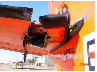
To achieve the greatest effectiveness, scarecrows must appear to be life like, be highly visible and must constantly change location to extend the length of their effectiveness (Bishop, McKay, Parrott, Allan, 2003). In the last few years several types of moving scarecrows have come into the market. An example of these is the spinning scarecrow as seen in figure 2.1.1. These “Whirly Ozidge” scarecrows are constructed of a reinforced PVC skin which is stretched over the aluminium frame and rotate in the wind around their central axis. The PVC skin is printed with an image of a human and a bright red and yellow panel to try to create the illusion of a threat to surrounding birds.
Figure 2.1.1 Rotating Scarecrows (Scaring Birds Website)
[image:19.595.264.388.632.748.2]Another type of moving scarecrow is the Scarey Man® made by Clarratts. The “Scarey Man” is an 165cm plastic scarecrow that runs off a 12 volt car battery. The scarecrow rapidly inflates about every 18 minutes and lasts for 25 seconds. During its inflation period the Scarey Man® emits a high pitched wail, and if at night illuminates.(See Figure 2.1.2).
Ultimately, however lifelike scarecrows are, they do not pose a significant enough threat to scare birds. Therefore to improve the threat that scarecrows create it is recommended that these devices are combined with actual human activity or audio deterrents (Bishop, McKay, Parrott, Allan, 2003).
2.1.2 Corpses
An alternative method used to deter birds has involved deploying replicas or even actual corpses of birds in a way that signals danger. Birds often approach the corpse out of curiosity but leave when they see the unnatural position. Although this technique is inexpensive, it's effectiveness varies depending on whether the corpse is continually moved and the availability of alternative sites for the birds to relocate. As with most visual deterrents it is recommended that this device is used in conjunction with others to be successful for a significant period of time.
2.1.3 Kites
Hawk kites are mobile devices that act as a predators to create a threat to birds in the surrounding area. Most kites bear the image of a soaring eagle outline and are tied to the ground. Studies have shown that hawk kites are ineffective in deterring birds from crops (Conover, 1983) but however, are effective when flown beneath helium balloons to create a sufficient threatening movement.
effective for a short period of time and over a small area.
There are also several other visual deterrents that are on the market today including mirrors, hawk-eyed balloons, large hawk eyes. These deterrents however are not as common or effective and are only suited to smaller areas.
2.2
Audio Systems
Audio deterrents are the most commonly used device in avian pest management. They operate by omitting either bird calls or ultrasonic sound waves to rid the surrounding area of birds. Most audio devices use either bird distress calls or predator calls and generate them randomly from different locations around the area.
2.2.1 Bio-Acoustic Devices
Bio-Acoustic deterrents are devices that transmit biological significant sounds such as bird alarm and distress calls. In nature, birds use alarm calls when they perceive danger, whilst distress calls are used when birds are captured, restrained or injured(Bishop, McKay, Parrott, Allan, 2003). Each call is species specific, however some distress and alarm calls are known to get a response from other species.
airfields, once the equipment has been bought and staff trained (CAA 2002). In deterring birds from airports, the distress call is emitted for 90 seconds from a distance of 100 m from the target flock to keep reactions predictable.
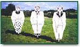
Figure 2.2.1 is an example of the “Bird Chaser” system that uses a motion sensor to trigger distress and alarm calls.
Figure 2.2.1: Bird Chaser (www.pest-control.bz)
2.2.2 Ultrasonic Devices
Other such bird deterrents such as ultrasonic systems which emit frequencies 21-26kHz in order to deter birds from areas such as warehouses, manufacturing plants, arenas, and loading docks. One of the current systems on the market is the Bird Chase Ultrasonic from Bird-B-Gone (Figure 2.2.2)
Figure 2.2.2 Bird Chase Ultrasonic (BirdBGone Website)
2.3
Light Systems
2.3.1 Strobe Lights
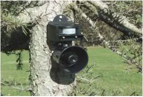
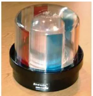
Flashing, rotating, strobe and searchlights are novel stimulus to birds, which encourage an avoidance response (Harris and Davis 1998). Although stationary lights are known to attract birds at night, bright, flashing, revolving lights cause a blinding effect which causes confusion. Light systems are designed for deterring birds from roosting and feeding in specific areas and are most effective between dusk and dawn (Blackwell, Bernhardt, Dolbeer, 2002).
[image:24.595.246.407.573.738.2]Studies conducted on light systems have shown that high intensity strobe lights caused birds to take evasive action and move away from some airfields (Pilo 1988). In the same study it was found that a randomised selection of two strobe frequencies increased the effectiveness over a range of species and that the strobes stopped all bird habitation.
The above Figure 2.3.1 is the BirdLite, which generates coloured flashing light by rotating at various speeds and illuminating different sections of its outer case. Light deterrents such as the BirdLite are easy to deploy and require little maintenance, however should not be used in areas where they might cause a visual nuisance to surrounding properties. The are also no very effective during daylight hours and their ability to deter birds is species dependant. Light deterrents are best used with a combination of other methods.
2.3.2 Lasers
As the demand for non-lethal, environmentally safe methods of bird scaring has increased, interest has grown in the use of lasers, particularly low-power lasers that work under low light conditions (Bishop, McKay, Parrott, Allan, 2003). The low power levels, distance, accuracy and silence makes lasers an attractive choice when choosing a method of bird control.
The typical laser used in this deterrent type is a Class III B laser which has been found to be safe to use by the United States Department of Agriculture (Blackwell, Bernhardt, Dolbeer, 2002). The classification Class III B refers to lasers that have a power rating between 5 and 500 mW and are generally not capable of producing hazardous diffusion unless directly pointed at the eye.
Figure 2.3.2: Avian Dissuader (SEA Tech Website)
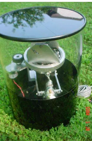
Since then spinning and scanner laser systems are being and have been developed with a line scanning system currently being used at the Montpellier Airport in France. SEA Tech the developers of the Avian Dissuader are also conducting trials on a rotating laser in conjunction with the University of South Dakota and should have a commercial product in the near future (See Figure 2.3.3).
[image:26.595.252.400.483.709.2]The use of lasers can be an effective method of bird scaring, although there is some evidence to suggest some birds are laser-resistant (McKay, 1999). Laser equipment is expensive and specialised training and safety precautions need to be in place in order for sound bird deterring practice to be achieved. As the effectiveness of the lasers decrease with increased light levels, their use in bird deterrence is only feasible from dusk till dawn and with hand held lasers requiring a user the overall cost of the deterrent is increased. New technology such as rotating and scanning laser systems has made obsolete, however these systems lack accuracy and the ability to keep non-target disturbance to a minimum.
2.4
Chemical Systems
2.4.1 Taste Repellents
Taste repellents can be divided into primary and secondary repellents. Primary repellents are agents that are avoided upon first exposure because they smell or taste offensive or cause irritation. Secondary repellents are not immediately offensive, but cause illness or an unpleasant experience. Following the ingestion of the secondary repellent, the bird then relates the taste to a unpleasant experience and avoids future encounters(Bishop, McKay, Parrott, Allan, 2003).
For taste repellents to be effective regular spraying and persistence is required (McKay and Parrott, 2002).
2.4.2 Tactile Repellents
Tactile repellents involve the use of sticking substances that discourage birds because of their 'tacky' feel. They can be applied as clay-based seed coatings, or as pastes and liquids on ledges and other roosting structures to deter settling birds (Bishop, McKay, Parrott, Allan, 2003).
An example of a tactile repellent is the Hot Foot Repellent Gel (See Figure 2.4.1). It is opaque in appearance and has a lower toxicity than table salt.
Figure 2.4.1 Hot Foot Repellent Gel (Hoot Foot Website)
2.5
Structural Systems
2.5.1 Wires
A common problem in large cities is the number of birds that roost on buildings and cover them in droppings. For this reason static structural deterrents have been developed and are used on many modern buildings. The main criteria in structural deterrents apart from deterring birds, is to be subtle and unnoticeable.
Overhead wires can be an effective method and low cost method of deterring birds. Many types of lines can be used but it is their spacing and height that appear to determine the bird species against which they are most effective (Bishop, McKay, Parrott, Allan, 2003). Wire systems can be relatively cheap to install and maintain, however require constant checking for broken lines that will be exploited by bird pests. They are a successful means of bird deterrence on large sites but are probably more effective on roof tops and ponds and small open areas.
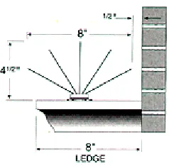
2.5.2 Spikes
Figure 2.5.1 Bird Spike 2001 (Bird-B-Gone Website)
The spikes on these systems vary in length and orientation but act as a physical barrier to prevent birds from landing in all cases. These systems are relatively expensive and are easy to install however as with wires require constant checking to remove debris which may cover the spikes. Due to the sharpness of the tips and the danger they create this deterrent is illegal for use in some countries (Turner 1998).
2.5.3 Electric Track
2.6
Hybrid Systems
2.6.1 Gas Cannons
Gas Cannons are devices that produce loud banging noises by igniting flammable gases. The scaring effect they create is similar to the effect that firing a shot gun has on birds. The unexpected bang causes a 'startle' reflex and promotes the bird to panic and fly away (Harris and Davis, 1998). Inside the cannon the mixture of gas and air pressure is ignited at a frequency adjusted by the gas feed, or and electric timing device.
Most gas cannons produce noise levels up to 130dB at regular intervals, with some having additional features such as a double detonation or a rotator to change the direction of sound. They are commonly used in agricultural areas, but have been known to be used in aquaculture operations and on aerodromes (Bishop, McKay, Parrott, Allan, 2003).
Figure 2.6.1 Propane Gas Cannon (BirdBlaster Website)
(1993) found that the intensity of sound output from gas cannons was highly variable between guns, and between explosions of an individual device. Conditions such as wind strength and direction played a large part in the intensity of the cannons.
Despite the amount of sound these devices produce they are relatively ineffective in deterring birds if they are moved or fired randomly and are not recommended for bird control by the Civil Aviation Authority (2002).
2.6.2 Other Devices
Another type of hybrid deterrent is the “Scarecrow” (See Figure 2.6.2). This deterrent is controlled by a motion sensor that sprays a jet of water once movement is detected. The shape of the “Scarecrow” is also designed to resemble a large predator bird to act as an additional visual deterrent. This device is relatively ineffective in scaring birds because its effective area is governed by how far the water jet can spray, and how far the sensor can detect movement. This device is best used very small areas such as residential gardens .
One of the most complex bird deterrents on the market today is the “Bird Blaster” deterrent. This system uses a network of pressurised tubes that surround a Doppler radar that is used to sense birds in the surrounding area. At various locations in the tube are t-sections that have short pieces of tube that are controlled by solenoids. When a bird comes into the radar, the system controls the closest solenoid to the bird to open which in turn lets the pressurised air escape creating a hissing noise and a 'waggling' motion. This system tries to imitate a snake to induce a 'startle' reaction from the bird. Despite the autonomous nature of this deterrent system it is relatively ineffective in scaring birds because the length of the tubes do not create a significant enough threat.
2.7
Evaluation of Current Bird Deterrent Systems
2.7.1 Method of Evaluation
To evaluate current bird deterrent systems a set of criteria needs to be determined with a corresponding grading scale. As mentioned in the introduction the aim of this project is to design a system that is effective, and yet non-intrusive which makes these two criteria the most important. In this evaluation other factors such as cost, physical requirements and area covered will also be used to determine the best deterrent to undergo automation.
results summed for each deterrent. Once this is completed, averages can be calculated to determine the deterrent that best meets the criteria.
Due to the lack of testing and information of some types of bird deterrents the below table only takes into account 17 of the current commercially available deterrents with many values of area covered and cost being taken from suppliers documentation. In cases where little or no information was available the effectiveness and area covered results are only hypothesised values in comparison to the other deterrents.
Table 2.1 Evaluation of Bird Deterrents Name Cost (1) Requirements (1) Area Covered (2) Stealth (2) Effectiveness (3) Automation Ability (2) Total (10) Motion Sensing
Water Spray $74.954 Electricity,Water 2
140 m2
2 Good2 Poor2 Fair3
Score 4 2 4 4 6 6 26
Taste Repellent
Gel $16.005 None5 NA2 Good4 Poor2 Very Poor1
Score 5 5 4 8 6 2 30
Wires NA
3 None4 NA3 Good4 Fair3 Very Poor1
Score 3 4 6 8 9 2 32
Ultrasonic System $225.00 3 Electricity 3
557 m2
4 Good 4 Very Poor 1 Poor 2
Score 3 3 8 8 4 4 30
Shock Track Various
3 Electricity3 NA3 Excellent5 Poor2 Very Poor1
Score 3 3 6 10 6 2 30
Spikes $220.20 3 None 4 NA 3 Fair 3 Poor 2 Very Poor 1
Score 3 4 6 6 6 2 27
Hawk Kite $59.95 4 None 4 NA 3 Poor 2 Fair 3 Poor 2
Score 4 4 6 4 9 4 31
Hot Foot $50.50 4
None 4
NA
2 Good4
Fair 3
Very Poor 1
Score 4 4 4 8 9 2 31
Corpses $7.50
5 None5 NA1 Fair3 Poor2 Very Poor1
Score 5 5 2 6 6 2 26
Revolving Hawk
Eyes NA4 None5 NA3 Poor2 Fair3 Poor2
Score 4 5 6 4 9 4 31
Movement Activated Audio Deterrent $75.00 4 Electricity 3
100 m2
2 Poor 2 Good 4 Fair 3
Score 4 3 4 4 12 6 33
Doppler Radar Controlled Compressed Air Tube Varying 2 Electricity, Air Compressor 2
930 m2
4 Poor 2 Fair 3 Good 4
Score 2 2 8 4 9 8 33
Propane Cannon $790.00
2 Propane Gas,Spark Plug 2
NA
4 Very Poor1 Good4 Good4
Score 2 2 8 2 12 8 34
Scarey Man $1240 1
12 Volt Battery 4 6 Ha 5 Very Poor 1 Good 4 Very Poor 1
Score 1 4 10 2 12 2 31
Laser Deterrents $1300.0 0 1 Electricity, Operator 2 500 m
4 Excellent5 Fair3 Good4
Score 1 2 8 10 9 8 38
Strobe Light $250.00 3
Electricity 3
930 m2
4 Poor 2 Good 4 Fair 3
Score 3 3 8 4 12 6 36
Revolving Scarecrows NA 4 None 5 NA 3 Poor 2 Fair 3 Very Poor 1
Score 4 5 6 4 9 2 30
2.7.2 Results of Evaluation
From the above table, the two bird deterrent systems that best matched the criteria were the strobe light and the laser deterrent. Both deterrents scored above the average of 31.17 and scored well in most areas with the cost of the laser system being lowest scoring category. Therefore the decision on what deterrent to automate for this project was between the laser deterrent and the strobe light with each having its advantages and disadvantages.
Laser deterrents are an effective, silent, highly directionable and almost undetectable form of bird deterrent which could be easily automated. However this technology comes at a high financial cost of around $2000 per unit and also creates many safety issues when being used around humans due the Class III B power rating. It would also be very difficult to create an effective laser deterrent that could achieve the accuracy of a birds eye and to compensate for this a larger laser would be required which would also greatly increase the cost.
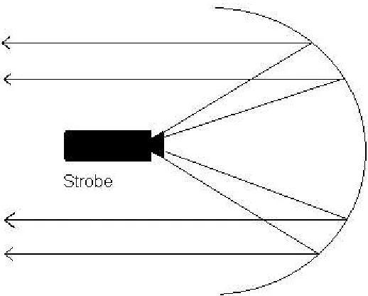
Therefore the strobe light has been chosen as the best deterrent to automate due to its relatively low cost, effectiveness and area covered. Due to the fact that strobe lights can cause a nuisance to neighbouring properties in open areas (Bishop, McKay, Parott, Allan, 2003) a directional strobe will be used in order to only effect desired areas. To achieve this, the strobe light will be placed at the focal point of a parabolic concave mirror in order to produce light only in one direction (See Figure 2.7.1 below).
Figure 2.7.1 Directional Strobe Light
Chapter 3
Machine Vision
3.1
Image Acquisition
Machine Vision is the use of computers to analyse situations and actions through the use of digitised video footage. To achieve this the images used must converted from film to digital information in order for a computer to process it.
3.1.1 Single Point Scanning
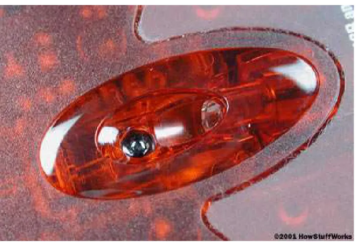
Current optical mice however use a tiny camera to take hundreds of pictures every second. The new optical mice use a small, red light-emitting diode (LED) to bounce light off that surface onto a sensor (See Figure 3.1.1). The sensor then sends each image to a processor for analysis which detects patterns in the images and compares those patterns to the previous image (Brain, c. 2001). The processor then determines the direction and distance that the mouse has moved from previous image and sends the corresponding coordinates to the computer.
Figure 3.1.1 Optical LED and Sensor (Howstuffworks Website)
3.1.2 Line Scan Devices
Line scan devices use a small photo sensor with a lens and light to analyse images one line at a time. Perhaps the most common example of a line scanner is the modern fax machine. It works by reading one line of a document at a time and determining whether each point is black or white then turns that data in to information that can be sent via the phone line. Figure 3.1.2 is an example of what a line scan device ' sees ' when a capital E is passed by.
Figure 3.1.2 Line Scanned Image
3.1.3 Frame Scan Devices
Frame scan devices come in 2 main forms, a digital camera which requires a software buffer to retrieve image information or an analogue camera which requires a hardware frame grabber to digitise the information. In this instance web cams will be the only considered image capturing device due to their relatively low cost and ease of connection to most household personal computers.
Web cams use Complementary Metal Oxide Semiconductor (CMOS) technology in order to capture an image. They are very cheap to manufacture and use little power, but have a low light sensitivity causing them to only have low resolution. A CMOS camera uses a sensor that is made up of a collection of tiny light sensitive diodes called photosites that store charge that is proportional to the light which they receive. Once the photosites have received the light from the image they charge they create is then digitised be the web cam and sent via a Universal Serial Bus (USB) cable to the computer. Each pixel of the image is stored as a number in a array which is used to tell the computer what colour goes in what position. In a black and white camera the values of each pixel range from 0 to 255 with each value representing a different shade of grey (See Figure 2.8 below).
For colour pictures, each pixel contains three values, relating to the amount of red, green and blue in that location. This is referred to as RGB which can produce almost any colour by using different amounts of red, green and blue.
Frame Scan devices are useful in determining shapes and movement of objects to a high degree of accuracy. They are superior to other image acquisition devices in the areas of locating and recognising objects however are the slowest due to the amount of information contained in each image. A frame scan device will be used in this project to locate a birds position relative to the camera with the possibility of also having the ability of recognise non avian movement.
3.2
Basic Image Processing
There are countless ways in which images can be processed to achieve a variety of different results. Through software processing computers can recognise shapes, patterns, objects, and movement to determine relevant information pertaining to a specific point of interest.
Another commonly used tools in image processing is edge detection. It can be done in a variety of different ways with the most basic form being the use of numerical filters. Numerical filters are 3 by 3 matrices that act as multipliers to pixel values in dual colour images. Below is a commonly used numerical filter for tracing around the edges of and object.
1 0 1 0 -4 0 1 0 1
Edge detection can also be done in a variety of other ways which include edge tracing methods or mathematical methods such as the Sobel edge detection. Edge tracing techniques are routines that which compare surrounding pixel values to a starting point and then follow the directions which are of similar values. By doing this lines of constant colour and light are drawn around objects which can be used for further analysis. Tracing techniques can used to generate graphs of direction of movement against length of movement which is a very useful technique in recognising shapes and objects.
[image:43.595.256.396.665.732.2]Sobel edge detection is a mathematical technique which is used in many machine vision applications. It is similar to the numerical filters described before however uses two filters which are then used to calculate the edge gradient at each point. The filters used in Sobel edge detection are below with Figure 3.2.2 representing the magnitude of the gradient.
Figure 3.2.2 Magnitude of Gradient (Fisher, Perkins, Walker, Wolfart, 2003)
The angle of orientation of the line relative to the pixel grid is then found using the following equation.
Figure 3.2.3 Angle of Orientation (Fisher, Perkins, Walker, Wolfart, 2003)
The Sobel image created using these equations can then be combined with a mathematical process called the Hough transform which is used to determine features in the image. The Hough transform can be used to identify the parameters of a curve which best fits a set of given edge points in order to extract the important information out of a picture. This method is rather complicated but achieves accurate results as seen in Figure 3.2.4.
3.3
Applications for Machine Vision
3.3.1 General Applications
Machine vision is a useful tool that can be used in a variety of applications. Through different image analysis techniques, machine vision provides opportunities to view images to either recognise objects, predict movement, measure dimensions, and/or record data. One of the most commonly used applications of machine vision occurs in the manufacturing and processing industry. Common examples in these fields are cameras that are used to detect defects in materials or products, and cameras that detect if there is an problem in the assembly lines. In these cases machine vision reduces inefficient production and ensures that products are of the highest quality.
3.3.2 Case Study
The following case study was conducted by James Matthews in 2003/4 to develop an intelligent closed circuit television (CCTV) monitor that would track individuals in a computer room. The system was also designed to determine whether individuals were stationary or standing and moving around the room.
From the initial observations of the test area, a few problems arose that needed to be dealt with. The problems were:
• Periods of inactivity - There were long periods of time where not much movement occurred among computer users.
• Height and Blocking - The height of the camera was relatively low which made it difficult to see all areas of the room and if someone was close to the camera other objects became hidden.
• Movement - As people sat down only very small amounts of their body could be seen and they also created movement in the same spot as someone in a different who was behind them.
• Other Moving Objects - When people got up off their chairs the rotation and lifting of the chair made it look like movement was still
• Screen movement - Screen changes such as the screen savers on each computer were detected as movement
Examples of these problems can be seen in Figure 3.3.1 below.
Figure 3.3.1 Sample Screens for Observation (Matthews, 2003)
Although all of these problems are not common to vision applications an analysis such as this is useful to for see problems which could occur in bird scaring. Obviously problems such as screen savers will not be common in bird deterrence other instances such as trees moving in the wind and multiple movements or multiple birds must be considered.
3.4
Vision Applications in Bird Deterrence
As seen already there are large numbers of different tools and techniques that can be useful in the area of bird scaring. For this project however the focus will be first on image comparison and the later on edge detection and shape recognition depending on time. The device chosen for image acquisition was the Logitech Quickcam because it connects directly to a PC via a USB cable and has a digital output. The computer then receives the images and converts them into a digital byte in order for the image manipulation and analysis to occur.
[image:48.595.148.507.580.747.2]The first part of the image analysis involves dividing the screen into nine separate sections each corresponding to a movement of the mechanical device mentioned in chapter four. Each section of the screen is compared to its previous image with the area with the highest amount of change containing the movement and hence bird location (See Figure 3.4.1). Once this system is stable and reliable additions such as edge detection will be made so that dramatic light sources such as strobe lights can can be used without creating a significant change in pixel values in all areas.
Chapter 4
Mechanical Design
4.1
Conceptual Design and Requirements
[image:49.595.243.402.599.738.2]The main conceptual design of this deterrent is to have a camera that is mounted on a mechanical system that can rotate and tilt to constantly have its target centred in its view of the camera. It must easily adapt to different types of deterrents such as the directional strobe light and laser deterrent and be able to connect to a PC. The movement required to move the camera and deterrent device must be able to be controlled by the computer and have switches that indicate the limits of movement. From these requirements the following device was conceptualised.
The camera captures the images and transmits them via the USB cable to the computer. After the image is analysed the computer, it then outputs a signal via the parallel port to the H-bridges (more detail in Section 4.3) that drives the motors in the desired direction.
[image:50.595.214.439.301.503.2]The motor in the lower section is a geared DC motor which turns the shaft which is connected to the rotating base in a rack and pinion type configuration (See Figure 4.1.2 below).
Figure 4.1.2 DC Motor and Gears
4.2
Material Selection
The material selection for this project is not of a great importance because no critical loads are being carried and no significant force is created. The selection of the material was then mostly based on categories such as cost, availability, weight and workability. Light metals such as aluminium were considered but however, were not selected because of their ability to create electrical interference. Therefore MDF was chosen as the construction material because of its low cost (Approx $20/m2) and inert nature.
[image:51.595.115.403.521.728.2]MDF or Medium Density Fibreboard is a type of hardboard that is made from wood fibres that are glued under heat and pressure (Lung 2004). It is dense, flat, stiff, has no knots and is easily machined. A list of its properties are in Table 4.2 below.
Table 4.2 Properties of MDF (EximCorp Website)
Thick Panel
12-21mm Unit Value
Density Kg/CUM 720 - 740
Internal Bond KPa 800
Modulus of Elasticity MPa 3000
Modulus of Rupture MPa 38
Screw Holding on Face N 1100
Screw Holding on Edge N 900
Moisture Content % 6
4.3
H-Bridge
To drive a normal DC or Stepper Motor, both sides of a battery are connected to the both sides of a motor causing it to spin in one direction. When the poles of the battery are swapped the motor then spins in reverse. Pulsing the voltage and current into a motor on and off powers the motor in short burst and gets varying degrees of torque, which usually translates into variable motor speed. These facts are useful in many situations, however more often bidirectional motor control is needed in places where operation cannot be stopped to change terminals.
[image:52.595.181.471.457.733.2]However to control the motor in both forward and reverse directions with a processor, a H-bridge is required (See Figure 4.3.1 below).
In the above figure drivers A and B are the relays that control the positive voltage to the motor called sourcing current. The C and D drivers control the negative voltage to sink current to the motor. As seen in the truth table above to spin the motor in one direction opposite corners of the H-bridge need to be turned on (See Figure 4.3.2 below).
Figure 4.3.2 Forward Current Flow (Brown 1998)
4.3.1 Transistor Driven
Transistor driven H-bridges operate in a similar way to the relay H-bridge in Section 4.3 with the relays replaced by PNP and NPN FET transistors. The PNP transistors in this case replace relay A and B due to the fact that P-channel FETs are good at sourcing current. Relays C and D are replaced with NPN transistors or N-channel FETs to be used to sink the current in the circuit. To protect the transistors from back EMF and burn out, a diode needs to attached across each transistor (See Figure 4.3.1).
Figure 4.3.3 Transistor Driven H-Bridge (Brown 1998)
4.3.2 Commercial Packages
[image:55.595.112.543.333.518.2]There are a few commercial H-bridge packages on the market today, the most common being the L298 Full-Bridge Driver made by ST Microelectronics (See Appendix C for data sheet). The L298 chip contains 2 H-bridges and can handle currents of approximately 1 amp and a peak current of about 3 amps (Brown 1998). Below is the typical configuration of the L298 used to as a H-bridge.
Figure 4.3.4 Sample L298 Configuration (ST Electronics)
4.4
Motor Selection
4.4.1 Stepper Motors
Permanent Magnet stepper motors incorporate a permanent magnet rotor, coil windings and magnetically conductive stators (Haydon Switch and Instrument Motors). They are called stepper motors because their rotation is induced by turning on different electromagnets in steps as shown in the figure below.
In Step 1 the phase A electromagnet is turned on. This magnetically locks the rotor in the position due the attraction of the opposite poles. In Step 2 phase A is turned off and phase B is turned on, rotating the rotor by 90°. This process of turning on and off the phases is repeated at an increasing speed to a stage where the motor is spinning at a constant velocity. This method of stepping is very coarse and requires a significant time to build up speed. To improve this, half stepping can be used. Half stepping is achieved by turning on two phases at the same time. By doing this the rotor is locked between the two phases rotating only 450 instead of the full 900 step. The disadvantage of half stepping is that there is a 15-30% less torque than full stepping due to the smaller electromagnetic force (Haydon Switch and Instrument Motors).
Stepper motors are useful in a variety of different situations with the ability to produce adequate amounts of torque and a fairly accurate amount of rotation. They also however, can easily miss steps and are rigid in movement which can create problems when trying to gain position feedback. Therefore stepper motors are not suited to the deterrent device in this project which requires smooth continual movement.
4.4.2 DC Motors
brushes which ride on the commutator (2002 Schreyer). An example of the inner workings of a typical motor can be seen in Figure 4.4.2 below.
Figure 4.4.2 DC Motor (Howstuffworks Website)
DC motors have varying properties which depend on the size and the power of each motor. They differ to stepper motors because they do not require time to build up speed and can easily reach a constant velocity without missing steps or losing accuracy. The shortfall with DC motors is that they require a potentiometer to determine position or amount of rotation which adds costs to the overall system. Despite this fact DC motors have been selected for use in this project due to their ability to maintain a constant smooth flow of velocity to the system and because position feedback is not needed at this stage in design.
4.5
Electrical Schematic
[image:59.595.118.535.293.536.2]The diagram below is a general overview of the connections and components of the deterrent system. The diagram shows the two H-bridges that control the movement of the system in their final configuration with the addition of the limit switches which are connected all connected to the parallel port.
Figure 4.5.1 Overall Electrical Schematic
Figure 4.5.2 H-Bridge Detailed Design
The limit switches are powered by the parallel port are return a TTL signal to a data line when a limit is reached. The switches are powered by always outputting a 5V logic high from lines in the port to which both switches for each axis is connected (See Figure 4.5.3 below).
[image:60.595.120.525.545.722.2]4.6
Final Design and Construction
Once all of the initial systems and components of the design had been selected, the next stage was to determine how to interface the components to obtain a fully functioning prototype and a method of construction. At this stage of development the most effective design process was actually building the prototype and testing the theory in order to verify the design. Therefore the first step in the construction of the prototype was sizing and preparing the MDF base for the configuration of the rest of the design.
4.6.1 Base
A 1200 x 450 mm section of MDF with a thickness of 12mm was selected for use as the base of the deterrent. The section was then cut to a 500 x 450 mm rectangle to increase the mobility of the system and to create sections that could be used later in the construction of the uprights (See Section 4.6.3). A 10mm hole was then drilled slightly off centre of the base (See Appendix D) in which the central axis of the deterrent will exist. The bottom disc is then used with a bolt to locate the position of the motors and gears with respect to the disc so that motor mounting holes can be drilled. Once this is complete two 3 mm holes are drilled for each motor which are 180 degrees apart. Adhesive feet were then also added to the corners of the base in order to reduce rocking during operation and to provide a flat surface. Once the construction on the base was complete the next stage was determining the method of driving the rotational base through gearing.
4.6.2 Gearing
[image:62.595.125.529.335.617.2]The selection of gearing for the prototype was very limited because of its small size. Therefore the type of gearing selected was a universal gearbox and ladder chain and sprocket set made by a Tamiya which is leading manufacturer in toy and hobby equipment. These mechanical components were chosen because they were readily available and because they were a tenth of the price of the nearest competitor. A diagram of the universal gearbox can be seen in Figure 4.6.1 below.
Figure 4.6.1 Tamiya Universal Gearbox (Tamiya, Inc.)
Figure 4.6.2 Gear and Chain Configuration
The gear in the above figure has an interference fit with the shaft to prevent slipping and the chain is attached to the rotating base with glue. Initially the design only specified one motor to control the movement of the disc however through limited testing another was added to reduce the amount of torque required by the motors and also to increase the stability of the rotation.
4.6.3 Disc
The disc or rotating base is the combination of the two vertical uprights and the disc on which the systems rotates. The uprights are made out of the cut off section of the MDF used for the base and are 250 x 120 mm in size. Each upright also has a 5 mm diameter hole centred 60 mm from the top of the section where the shaft is located. The base is a 150 mm diameter PVC end cap that is commonly used for hydraulic applications which was selected because of its low cost and shape (See Figure 4.6.3 below).
Figure 4.6.3 Disc Construction
4.6.4 Camera Mount
[image:65.595.210.443.385.693.2]The camera mount is the member that connects the camera to the shaft of the gearbox. It is constructed out of the remaining MDF from the base, and is attached to the output shaft using an interference fit. The mount is a 30 x 30 mm square which has been designed to fit the Logitech camera selected in the Section 3.4. The Logitech camera fits into the 8 mm hole and is fixed in place by adhesive in order to increase stability. The camera mount at this stage of development was only designed to fit the camera and will need to be modified to include a deterrent. A picture of the camera fitted to the mount can be seen in Figure 4.6.4 below.
4.6.5 Electrical Circuits
[image:66.595.192.462.382.583.2]The electrical circuits for the system are configured as specified in Section 4.5 with each H-bridge having different families of transistors due to the availability of components. Each H-bridge circuit was constructed on small 80 x 60 mm bread boards which were selected to increase the adaptability of the system and increase the speed in which the circuits could be constructed (See Figure 4.6.5 below). After the construction of the circuits and testing was completed, the H-bridge circuits were then attached to the base and an upright using silicon which is used to guard against electrical interference and moisture.
Figure 4.6.5 Bread Board Circuit
4.6.6 Final Design Overview
Once the prototype was fully constructed, implementation problems had become obvious. The first major problem that arose in the construction was the amount of friction between the disc and the base. Even though the surfaces were relatively smooth and flat head screws had been used, there was still a large amount of friction to overcome for the system to rotate smoothly. Various attempts with washers and bearings were trialled, however the final solution was to introduce a second motor and gearbox as mentioned in Section 4.6.2 which improved both the speed and the stability of the system.
Another problem was the the fit of the hexagonal shaft with the camera mount. Initially the fit was rigid, however after limited use the shaft had came loose. To correct this, a small end plate used for models was screwed to the side of the camera mount and then fixed to the shaft using a grub screw to minimise slipping.
Chapter 5
Software Design
5.1
Requirements and Specifications
The minimum requirement of the software for this prototype, is a program that can detect movement and control the motors to react in the appropriate way to the movement. The software needs also to be able to run on a standard desktop or laptop PC with the ability to output TTL signals via the parallel port and receive images from a web cam. Additional requirements such as the ability to preview the image, and the ability to run a user controlled mechanical test are other important functions which must be included in the code.
5.2
Programming Language Selection
The initial programming language selected for this project was Microsoft Visual C++ because of its power, support, and ability to create stand alone executable files. However after an initial investigation into the language, Visual C++ was found very complex and require additional packages such as the Direct X 9 software development kit to perform image processing. Therefore Visual Basic was selected as the programming language because of its simple nature and close relationship to Quick Basic. This language was also chosen because of the existence of software written by E.J. Bantz Jr. and Professor John Billingsley that related to image acquisition using a web cam.
5.3
Program Flow Chart
5.4
Image Analysis
The method of image analysis used in this software is similar to the methods mentioned in Section 3.2 with image comparison being the major technique used. The existing software written by E.J. Bantz Jr. and Professor John Billingsley accepts the images from the web cam and stores the pixel values into arrays in the form below.
w = Squiz.pwidth h = Squiz.pheight Debug.Print w, h
ReDim picbytes(2, w - 1, h - 1) As Byte
Do
Debug.Print "STA call "; stoppit Squiz.SnapToArray picbytes() Debug.Print "STA return"; stoppit i = DoEvents
For j = 0 To h - 1
For i = 0 To w - 1
p = picbytes(2, i, j)
q = picbytes(1, i, j)
r = picbytes(0, i, j)
Pic.PSet (i, h - j), RGB(p, q, r)
Figure 5.4.1 Image Comparison
Once the difference between the images is displayed the centre of the movement is then calculated from the green pixels using the following formula.
Centre of Movement =
∑
iNo. of Pixelsi ,
∑
j
No. of Pixels j=Average of Movement
From this equation the centre of movement is given as a pixel location which is then located with reference to a square grid of nine equal sections. Each section of this grid relates to the movement of the deterrent system with the top left section equalling a rotation by the base to the left and a positive rotation of the camera.
5.5
Graphical User Interface
When designing a graphical user interface (GUI) for a prototyped system many considerations must be taken into account. The GUI must contain a significant amount of important information whilst being simplistic, intuitive and easy to read. To achieve this the GUI was designed around the following three principles or primary human factors.
5.5.1 Visual Acuity
Visual acuity is the ability of the eye to focus on small areas. The retina of eye can only focus on about on a very small portion of a computer screen, or anything for that matter, at any one time (Jansen, 1998). At a distance greater than 2.5 degrees from the point of focus, visual sharpness decreases by half, therefore a circle of radius 2.5 degrees around the point is the maximum area a user can see clearly.
5.5.2 Gestalt Principle
The Gestalt Principle states that people use a top-down approach to organizing data and attempts to identify criteria that cause people to group certain items together in a display. For example, if the user knows where one item in a group is on a screen, he or she will expect other like items to be there also (Jansen, 1998). This grouping of similar information helps to improve the speed of operations of the user and minimises errors.
5.5.3 Information Presentation
Currently the amount of information present is the most basic of GUI design considerations and has shown that making screens less crowded improves screen clarity and readability. Therefore most modern GUI only present information that is relevant to the current operation. Empirical researchers show that limiting the information to that necessary for the user reduces errors and time to perform tasks. Errors and performance time increase as the GUI presents more information (Jansen, 1998).
5.5.4 GUI Features
[image:75.595.116.527.274.610.2]Figure 5.5.1 is a screen shot of the final design of the GUI. It conforms to the previously mentioned qualities of good GUI design by containing all the information needed by the user.
Figure 5.5.1 GUI Design
5.6
System Overview
This section contains a listing of the algorithms used in the control software for the prototype. The listing below is written in pseudo code to improve the readability of the program and to be in a format that can easily be changed to different programming languages. It is written in three sections, the mechanical test routine, the limit testing routine, and the general operation routine which calls the limit routine. A listing of the final developed code for this project is located in Appendix B and differs slightly to the pseudo code. The difference between these to listings and the problems encountered during programming can be found in Section 6.4.
5.6.1 Mechanical Test Routine
Mechanical Test
OnClickedMechTButton() IN Port = Limits
WHILE Limits = 0 {
OnClickedRadioButton()
Switch (Pos) {
case'1': OUT Port 00001010 //Top Left
case'2': OUT Port 00000010 // Left
case'3': OUT Port 00000110 //Bottom Left
case'4': OUT Port 00001000 //Top
case'5': OUT Port 00000000 //Centre
case'6': OUT Port 00000100 //Bottom
case'7': OUT Port 00001001 //Top Right
case'8': OUT Port 00000001 //Right
case'9': OUT Port 00000101 //Bottom Right
}
5.6.2 Limit Test Routine
LIMIT ROUTINE (LIMRT)
IN Port = Limits
While t > 0 {
Switch(Limits) {
case'00010000': OUT Port 00000001 case'00100000': OUT Port 00000010 case'01000000': OUT Port 00001000 case'10000000': OUT Port 00000100 }
t = t-1 //Time Constant
} Return
5.6.3 General Operation
General Operations
DO {
FOR j = 0 to height-1
FOR i = 0 to width - 1 p = picbytes(2, i, j)
q = picbytes(1, i, j)
IF q1 = q { Plot Red } ELSE { Plot Green x = i y = j S = S + x B = B + y }
RUN LIMRT
(S)/Last x = U (B)/Last y = V
Switch {
case U> 0.6* W & V > 0.6*H: OUT Port 00001010
case U> 0.6* W & V < 0.6*H & V> 0.3*H: OUT Port 00000010 case U> 0.6* W & V < 0.3*H: OUT Port 00000110
case U> 0.6* W & V > 0.6*H: OUT Port 00001010
case U> 0.3* W & U < 0.6*W & V> 0.6*H: OUT Port 00001000 case U> 0.3* W & U < 0.6*W & V< 0.6*H& V>0.3*H: OUT Port $00
case U> 0.3* W & U < 0.6*W & V< 0.3*H: OUT Port 00000100 case U< 0.3* W & V > 0.6*H: OUT Port 00001001
case U< 0.3* W & V < 0.6*H & V> 0.3*H: OUT Port 00000001 case U> 0.3* W & V < 0.3*H: OUT Port 00001000
q1 = q
Chapter 6
Improvements and Further Work
6.1
Introduction
6.2
Mechanical Design
As mentioned in Section 4.6.6, the final constructed prototype differed from the original design in may areas due to unforeseen problems and unpredicted behaviour. In this section the final resulting mechanical system will be assessed in relation to its effectiveness and from these results improvements will be suggested.
6.2.1 Base Rotation
Figure 6.2.1 Re-Designed Base
During the initial design phase and after some limited tests a second motor was selected to help control the rotation of the base. However after further testing the second motor was found to more of a hindrance rather than a help to the first motor. Due to slight differences in speed the first motor was slowed by the second because it had to take the initial load combined with the 101:1 gearbox to spin the base. Therefore the in the final constructed prototype only one motor and the second gearbox were used for rotation which was found to be sufficient.
6.2.2 Limits and Feedback
at the same time. Other benefits that come with position feedback is the ability to calculate and change the speed of the system and its response to situations.
To implement a form a position feedback the system would need to be revised in order to make room for items such as a rotatory encoder and its connections. With this in place with the addition of contacts the system would then have the ability to rotate 360 degrees greatly increasing its effectiveness. Therefore it is suggested that position feedback be included in the revised design of this system.
6.3
Electrical Design
The most significant problem with the electrical component of the system was the intermittent operation of the H-bridges. On both constructed circuits the controlled motor only operated correctly in one direction with little drive in the opposite direction. Initially this was thought to be a construction problem however after extensive analysis there was no fault in the circuit.
Due to the problems encountered, a redesign of the electrical system is needed for the deterrent system to operate correctly. The L298 package (Appendix C) is recommended to replace the transistor driven H-bridges because it can provide predictable results, and one chip can be used to drive a single motor. This package would greatly increase the reliability of the system and reduce the cost and time in development. The updated design of the electrical system would also need to specify that the control computer does runs an older version of windows or a Linux operating system.
6.4
Software Design
The final program for the control of the deterrent system remains incomplete with the limit routine and the mechanical test functions still to be written. These functions were not and cannot be written until the system hardware is fully functional because they require both inputs and outputs from the computer system. Pseudo code for these functions has been written and is listed in section 5.6 for use in future work. This stage of implementation is the final step before the total system tested.
The main operating program (See Appendix B) runs without error although has not been throughly tested. Testing opportunities were limited due to limited time and the absence of the win95io.dll file that is necessary for operation. Therefore further testing and improvement of this program is required for the software to be reliable and accurate.
Ideally for future additions to the software a faster computer is needed due to the large amount of data that is required in streaming video. Other additional hardware such as a frame grabber card would be a useful increasing the speed of the program by reducing the amount of information that needs to be processed by the software.
As mentioned in section 5.2, Visual C ++ was originally selected as the programming language for this system. It is a more powerful language than Visual Basic and can handle large amounts of data with ease. Therefore for future additions to this project it is suggested that the code be converted from Visual Basic to Visual C++ to improve the overall operation of the system.
Other additions such as edge detection and previously mentioned analysis methods would help to improve the accuracy and reliability of the system and therefor should be considered during re-design. With these necessary changes the control software will be fast and accurate enough to be effective in deterring birds.
6.5
Deterrent Application and Testing
Currently there exists no standard for bird deterrent testing which allows many inadequate products to enter the market place. Due to the non-existence of a standard the following test procedure is tailored to measure the performance of this designed deterrent system.
1. Mechanical 2. Electrical 3. Software 4. Deterrent 5. Overall System
The suggested test procedures for the deterrent system are listed below. These procedure were developed during implementation and list the necessary steps to ensure correct operation.
Mechanical Test Procedure
1. Ensure that all levers make contact with limit switches 2. Ensure all fixtures are secured
3. Rotate base with gears unattached and check for stability 4. Check that both shafts rotate
5. Check that both motors operate correctly and can drive load.
Electrical Test Procedure
1. Ensure all circuits are configured as per design
2. Test each H-bridge for correct operation and identical speeds in both directions 3. Test all limit switches
4. Run a trial operation of the system using a battery to supply TTL levels to the H-bridge.
Software Test Procedures
1. Run the Limit routine and activate switch by hand, checking I/O levels.
2. Run mechanical test routine using the radio buttons to control movement and configure the time constant for the limit routine
3. Test web cam image by previewing image and running a dummy program
4. Test Overall program by checking that the system responds to corresponding movement.
5. Measure the speed of the system and adjust to suit.
Deterrent Test Procedure
1. Ensure that the deterrent device is fixed securely and operates correctly.
2. Test the system to see that all components especially the software still operate correctly.
3. Conduct tests in laboratory to determine the range and speed of movement. 4. Conduct initial tests on a single bird in an enclosed area to determine the safety
of the system and its effectiveness
Overall Test Procedure
1. Obtain permission to conduct limited tests in a large bird avery
2. Study a the habits of birds at a particular location before, during and after the introduction of the deterrent device.
3. Analyse results and modify the system or method of use accordingly.
steps to be taken during initial and final testing. Once these procedures are complete the findings of the tests can then be published with then the opportunity to commercialise the product.
6.6
Further Project Work
This project sets a foundation that could be easily taken up as a future project. It covers the design process of the deterrent system and describes the problems encountered during implementation. Later sections suggest possible solutions to each of the problems and make reco