University of Southern Queensland
Faculty of Engineering and Surveying
Pile Driving Analysis Via Dynamic Loading Test
A dissertation submitted by
Mr. Yu Wah, YU
In fulfillment of the requirements of
Courses ENG4111 and 4112 Research Project
Towards the degree of
Bachelor of Engineering (Civil Engineering)
UNIVERSITY OF SOUTHERN QUEENSLAND ABSTRACT
ABSTRACT
During the pile driving, there are many problems to be concerned such as pile damage,
hammer performance to the pile, drivability of pile in various soil strata and determine
pile bearing capacity. Unfortunately, being the pile driven underground and therefore ‘out
of sight’ identifying those problems and therefore implementing remedial actions is
considerably more difficult than in structure placed above ground level.
This research gives an overview of most common testing method used to determine the
cause of pile damage and the pile bearing capacity during pile driving. By WAVE
equation, it can be predicted the desired pile bearing capacity with applicable hammer
configuration. However, this process is before pile driving and therefore the problems are
still ‘out of sight’. Thereafter, Case method is developed to monitor and identify the pile
defects and pile bearing capacity during pile driving and therefore those problems will
not be ‘out of mind’.
UNIVERSITY OF SOUTHERN QUEENSLAND DISCLAIMER
University of Southern Queensland
Faculty of Engineering and Surveying
ENG4111 & ENG4112 Research Project
DISCLAIMER
Limitations of Use
The Council of the University of Southern Queensland, its Faculty of Engineering and Surveying, and the staff of the University of Southern Queensland, do not accept any responsibility for the truth, accuracy or completeness of material contained within or associated with this dissertation.
Persons using all or any part of this material do so at their own risk, and not at the risk of the Council of the University of Southern Queensland, its Faculty of Engineering and Surveying or the University of Southern Queensland.
This dissertation reports an educational exercise and has no purpose or validity beyond this exercise. The sole purpose of the course pair entitled “Research Project” is to contribute to the overall education within the student’s chosen degree program. This document, the associated hardware, software, drawings, and other material set out in the associated appendices should not be used for any other purpose: if they are so used, it is entirely at the risk of the user.
Yu Yu Wah
UNIVERSITY OF SOUTHERN QUEENSLAND CANDIDATES CERTIFICATION
CANDIDATES CERTIFICATION
I certify that the ideas, designs and experimental work, results, analysis and conclusions
set out in this dissertation are entirely my own efforts, except where otherwise indicated
and acknowledged.
I further certify that the work is original and has not been previously submitted for
assessment in any other course or institution, except where specifically stated.
Yu Yu Wah
UNIVERSITY OF SOUTHERN QUEENSLAND TABLE OF CONTENTS
TABLE OF CONTENTS
CONTENTS PAGE
ABSTRACT i
DISCLAIMER ii
CANDIDATES CERTIFICATION iii
TABLE OF CONTENTS iv
LIST OF FIGURE viii
LIST OF TABLE x
CHAPTER 1 - INTRODUCTION 1‐1
1.1 - Introduction 1‐1
1.2 - Objectives 1‐10
1.3 - Organization of report 1‐11
CHAPTER 2 - LITERATURE REVIEW 2‐1
2.1 - Introduction 2‐1
2.2 - Dynamic analysis methods 2‐3
2.3 - Methods of dynamic analysis 2‐5
2.4 - Driving resistance criteria 2‐6
2.5 - Quality Control on Driven Piles 2‐8
UNIVERSITY OF SOUTHERN QUEENSLAND TABLE OF CONTENTS
2.6.1 - Wave Equation Analysis 2‐14
2.6.2 - Dynamic testing analysis 2‐15
2.6.3 - Static load tests 2‐15
2.7 - Drivability versus pile type 2‐16
CHAPTER 3 - DYNAMIC FORMULAS 3‐1
3.1 - Introduction 3‐1
3.2 - Accuracy of dynamic formulas 3‐2
3.3 - Problems with dynamic formulas 3‐3
3.4 - Dynamic formulas 3‐5
3.5 - Alternatives to use of Dynamic formulas 3‐6
CHAPTER 4 - DYNAMIC ANALYSIS BY WAVE EQUATION 4‐1
4.1 - Introduction 4‐1
4.2 - Wave propagation 4‐2
4.3 - Wave equation methodology 4‐4
4.4 - Wave equation applications 4‐8
4.5 - Analysis decisions for wave equation problems 4‐12
4.5.1 - Selecting the proper approach 4‐12
4.5.2 - Hammer data input, external combustion hammers 4‐15
4.5.3 - Hammer data input, diesel hammers 4‐16
4.5.4 - Cushion Input 4‐18
4.5.5 - Soil parameter Selection 4‐19
UNIVERSITY OF SOUTHERN QUEENSLAND TABLE OF CONTENTS
CHAPTER 5 - DYNAMIC PILE TESTING AND ANALYSIS 5‐1
5.1 - Introduction 5‐1
5.2 - Background 5‐1
5.3 - Applications for dynamic testing methods 5‐3
5.3.1 - Static pile capacity 5‐4
5.3.2 - Hammer and driving system performance 5‐4
5.3.3 - Driving stresses and pile integrity 5‐5
5.4 - Dynamic testing equipment 5‐6
5.5 - Basic wave mechanics 5‐12
5.6 - Dynamic testing methodology 5‐24
5.6.1 - Case method capacity 5‐24
5.6.2 - Energy transfer 5‐29
5.6.3 - Driving stresses and integrity 5‐31
5.6.4 - The CAPWAP method (Case Pile Wave Analysis Program) 5‐33
5.7 - Usage of dynamic testing methods 5‐40
5.8 - Advantages 5‐42
5.9 - Disadvantages 5‐44
CHAPTER 6 - TEST RESULTS 6‐1
6.1 - Introduction 6‐1
6.2 - Interpretation 6‐7
6.2.1 - Energy transfer 6‐7
6.2.2 - Driving stress 6‐7
[image:7.595.75.511.84.750.2]UNIVERSITY OF SOUTHERN QUEENSLAND TABLE OF CONTENTS
6.2.4 - Pile capacity 6‐8
CHAPTER 7 - DISCUSSION AND CONCLUSION 7‐1
7.1 - Discussion 7‐1
7.1.1 - Pile integrity 7‐1
7.1.2 - Stress on pile 7‐3
7.1.3 - Hammer performance 7‐4
7.1.4 - Pile capacity 7‐8
7.2 - Conclusion 7‐9
7.3 - Recommendation 7‐11
REFERENCE 1
APPENDIX A – PROJECT SPECIFICATION 1
UNIVERSITY OF SOUTHERN QUEENSLAND LIST OF FIGURE
LIST OF FIGURE
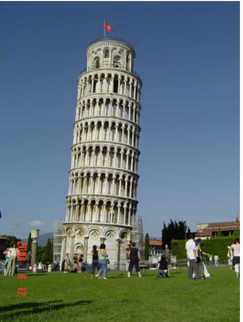
Figure 1-1 - Pisa of Tower in Italy 1-2
Figure 1-2 - Building collapse due to poor foundation, China (Jun-2009) 1-2
Figure 4-1 – Definition of parameters governing stress wave propagation in piles 4-4
Figure 4-2 – Typical Wave Equation Model 4-6
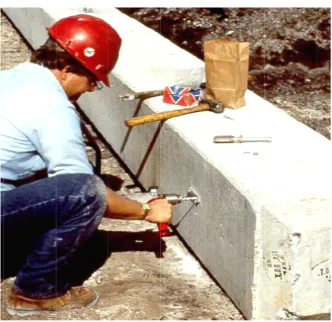
Figure 5-1 – Pile preparation for dynamic testing 5-7
Figure 5-2 – Gages bolted on pile 5-8
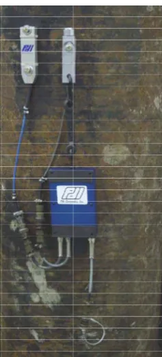
Figure 5-3 – Strain transducer and accelerometer bolted on the concrete pile 5-9
Figure 5-4 – Pile driving analyzer (courtesy of Pile Dynamics, Inc) 5-9
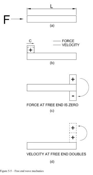
Figure 5-5 – Free end wave mechanics 5-14
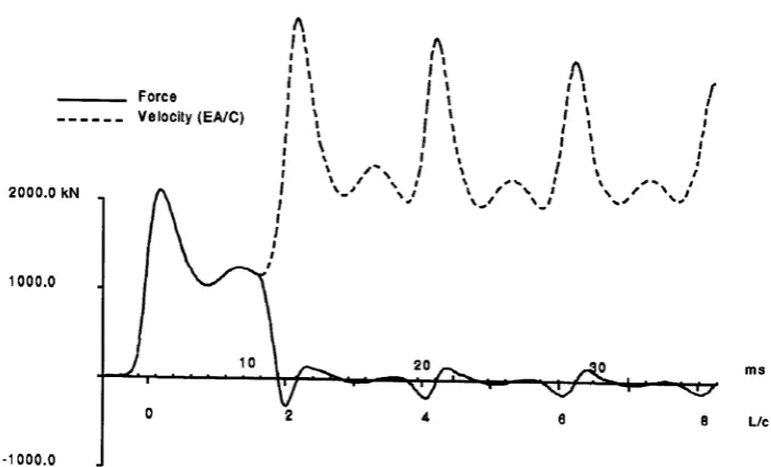
Figure 5-6 – Force and Velocity measurements versus Time for Free End Condition 5-15
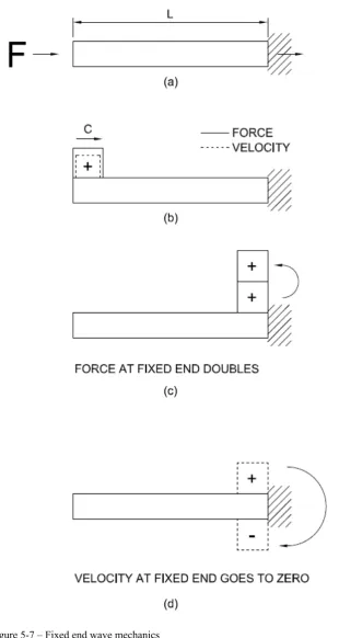
Figure 5-7 – Fixed end wave mechanics 5-17
Figure 5-8 – Force and Velocity measurements versus time for Fixed End Condition 5-18
Figure 5-9 – Soil resistance effects on force and velocity records 5-21
Figure 5-10 – Typical force and velocity records for various soil resistance condition 5-23
Figure 5-11 – Standard, RSP and Maximum, RMX, Case Method Capacity Estimates 5-28
Figure 5-12 – Energy transfer computation 5-31
Figure 5-13 – Schematic of CAPWAP analysis method 5-34
UNIVERSITY OF SOUTHERN QUEENSLAND LIST OF FIGURE
Figure 5-15 – CAPWAp iteration matching process 5-37
Figure 5-16 – CAPWAP final result table 5-38
Figure 5-17 – CAPWAP stress distribution profile 5-39
Figure 6-1 – Graphical presentation of energy transfer 6-3
Figure 6-2 – Graphical presentation of static capacity 6-4
Figure 6-3 – Graphical presentation of compressive stress 6-5
UNIVERSITY OF SOUTHERN QUEENSLAND LIST OF TABLE
LIST OF TABLE
Table 5-1 – Summary of Case damping factors for RSP equation 5-27
Table 5-2 – Pile damage guidelines (Rausche and Goble, 1979) 5-32
Table 6-1 – Summary of dynamic loading test result 6-2
Table 7-1 - Limits on driving stress (BSI, 2001) 7-4
Table 7-2 - Typical energy transfer ratio of pile hammers 7-7
Table 7-3 - Acceptance criteria of driven pile via pile displacement 7-8
UNIVERSITY OF SOUTHERN QUEENSLAND INTRODUCTION
CHAPTER 1 - INTRODUCTION
1.1 - Introduction
The role of foundation in superstructure is undeniably important especially in
high-rise building. From ancient periods, human had been already paid attention
to the foundation structure. It can be evidenced in the bible.
I will show you what he is like who comes to me and hears my words and puts
theme into practice. He is like a man building a house, who dug down deep and
laid the foundation on rock. When a flood came, the torrent struck that house but
could not shake it, because it was well built. But the one who hears my words
and does not put them into practice is like a man who built a house on the
ground without a foundation. The moment the torrent struck that house, it
collapsed and its destruction was complete.
[Luke 6:47-49 NIV (Circa AD 60)]
The above statement is well proving that the significance of foundation. Figure
1-1 and Figure 1-2 are showing the results of superstructure building on the poor
UNIVERSITY OF SOUTHERN QUEENSLAND INTRODUCTION
Figure 1-1 - Pisa of Tower in Italy
[image:13.595.200.439.105.422.2]Resource: http://www.flickr.com/photos/heute/337699799/
Figure 1-2 - Building collapse due to poor foundation, China (Jun-2009)
UNIVERSITY OF SOUTHERN QUEENSLAND INTRODUCTION
Deep foundations have been frequently used to support structures, such as
buildings, bridges, towers, and dams, in areas where the soil conditions are
unfavorable for shallow foundations. Two basic types of deep foundation are
well known as drilled shafts and driven piles. Drilled shafts are usually installed
by using hammer to drive the steel or concrete piles into the ground. This report
is concentrated on the improvement of design and quality control of driven piles.
Traditionally, the design of pile foundations is based on static analysis methods,
such as α-method, β-method, λ-method, Nordlund’s method, Meyerhof’s method,
SPT (Standard Penetration Test) method, and CPT (Cone Penetration Test)
method. However, the pile capacity estimated from static analysis based on the
soil parameters obtained from the laboratory test and in-situ test may not be
accurate. It can vary widely due to original nature of soil deposit, and different
soil testing and evaluation methods. Consequently, some type of load-carrying
capacity method of driven piles is needed in the field.
Static load test can serve as the ultimate verification of driven pile capacity,
though this method has still the unsettled question which concerns the definition
of failure load. However, the static load test is expensive and time-consuming to
carry out and thus can only be performed on a few selected driven piles. The
information obtained from static load test results cannot be easily estimated to
other piles at the site, leaving those other piles to be unverified. Besides, the
UNIVERSITY OF SOUTHERN QUEENSLAND INTRODUCTION
when to stop pile driving. Estimation of pile capacity based on observation
during pile driving is therefore an essential element in a pile driving practice.
With the creation of digital computers, synchronizing analysis of pile driving
problem during pile driving became possible. In 1960, Smith proposed the first
applicable wave equation method for pile-driving analysis. The wave equation
method was adopted by the engineers in the piling industry because it gave a
more accurate result. With the development and acceptance of PDA (Pile
Driving Analyzer), the Case method (Rausche et al. 1985), applying the
measured force and velocity in approximate simple algebraic equations, has
become one of the widely used methods to evaluate the pile capacities during
pile driving. However, the static soil resistances determined by the Case method
are very sensitive to assumed Case damping factor, and shaft and toe resistance
cannot be separated by the Case method.
In an effort to solve some of the weakness of the Case method, an alternative
procedure - the CAse Pile Wave Analysis Program (CAPWAP), was developed
by Rausche et al. (1972, 1985). The CAPWAP approach is based on the
one-dimensional wave propagation model suggested by Smith (1960). In the
CAPWAP analysis, the data (either force or velocity) is used as input to match
closely with the other by adjusting Smith model parameters. Once the acceptable
match is achieved, then the pile capacities and the Smith model parameters can
UNIVERSITY OF SOUTHERN QUEENSLAND INTRODUCTION
(1994), Hirsch et al. (1976), Liang and Zhou (1996), and Liang (2003) have
proposed various methods to interpret the measured force and velocity for
evaluating the pile capacity. However, the capacity estimation and drivability
predictions from dynamic pile tests are sometimes far from satisfactory. Thus,
the dynamic testing technique still needs to be further improved.
Nowadays, dynamic pile tests are widely adopted to verify when the design pile
capacity is reached during pile driving and to monitor the installation process to
avoid pile damage due to hammer impact. However, there is a lack of acceptance
criteria for the number of pile tests and measured capacity. Hannigan et al. (1998)
suggested that a minimum of two dynamic pile tests to be conducted for a small
project. For large projects or small projects with expected installation difficulties,
or significant time dependent capacity issues, a greater number of dynamic pile
tests are recommended. If the test piles do not reach a required design capacity,
the design load for the piles must be reduced or additional number of piles or
longer pile length must be installed. The recommendations of the number of
dynamic pile tests are totally based on engineering experience.
Paikowsky et al. (2004) provided recommendations for the number of piles to be
dynamically tested as well as the acceptance criterion for a set of driven piles.
The testing in manufacturing was employed to determine the number of dynamic
tests to be performed on production piles. However, the adoption of normal
UNIVERSITY OF SOUTHERN QUEENSLAND INTRODUCTION
the probabilistic characteristics of dynamic test methods can be properly
represented by the lognormal distribution, makes the recommendations very
conservative. The acceptance criterion for a set of dynamic test results is
subjectively chosen such that the average capacity of the tested piles is no less
than 85% of the ultimate capacity. In addition, the application of arithmetic
mean of measured capacity is far away from the actual cases of geometric mean
of measured capacity when the lognormal distribution is used to represent the
probabilistic characteristics of dynamic test methods. Therefore, there is a need
to develop more reasonable, reliability-based quality control criteria for driven
piles.
Since 1994, American Association of State Highway and Transportation
Officials (AASHTO) has been in process to change from Allowable Stress
Design (ASD) method to Load and Resistance Factor Design (LRFD) method
for foundation design. Whereas ASD considers all uncertainties in the applied
load and ultimate geotechnical or structural capacity in a single value of factor of
safety (FS), LRFD separates the variability of these design components by
applying load and resistance factors to the load and material capacity.
Comparing to ASD, LRFD has the following advantages:
z Accounts for variability in both resistance and load;
UNIVERSITY OF SOUTHERN QUEENSLAND INTRODUCTION
and rock for different limit states and foundation types;
z Provides more consistent levels of safety in the superstructure and
substructure as both are designed using the same loads for predicted or
target probabilities of failure.
The adoption of LRFD approach makes possible the application of reliability
analysis to quantify uncertainties joined to various methods for estimating loads
and resistances. In AASHTO LRFD specifications (2003), the resistance factors
for various design methods are recommended with calibrations mostly based on
the reliability analysis using available statistical data. The design of foundation
piles is usually performed with static analytical calculations using both of the
soil parameters from local geotechnical site investigations and laboratory test
results. The uncertainties related to the prediction method, the errors of
calculation model, and the spatial variability of soil parameters, are considered
in a single resistance factor recommended for a specific design method
regardless of individual site-specific situation. For each construction site, soil
profiles, soil types, pile driving equipment, and hammer performance, will be
unique. Thus, it is advantageous if a site-specific calibration for the resistance
factors can be performed to improve design.
With the use of both static load test and dynamic pile test, the pile length
UNIVERSITY OF SOUTHERN QUEENSLAND INTRODUCTION
either adequate or inadequate based on field pile tests during pile driving.
Therefore, the uncertainties of static analysis design method could be reduced by
dynamic test results. Vrouwenvelder (1992) presented an approach for including
either the static or dynamic test results to update the factor of safety in the ASD
method of driven piles. Zhang et al. (2002) demonstrated that the results from
static pile load tests could be included into pile design using Bayesian theory by
updating the resistance factor in LRFD. The practice in Ohio Department of
Transportation shows that more and more dynamic pile test methods have been
utilized to compare with static load test, due to saving in cost and time.
Recognizing that dynamic pile testing is much preferred pile capacity
verification method. A methodology needs to be developed to update the
resistance factors for static analysis method by utilizing dynamic pile test results.
The fact is that axial capacity of a driven pile may change over time after initial
pile installation has been reported by a number of geotechnical engineers for
many years. The increase of pile capacity with time is usually referred to the soil
set-up. Oppositely, the decrease of pile capacity with time is often named as soil
relaxation. Due to pile driving, soils around the pile are disturbed and remolded,
and excess pore pressures are generated. With passing of time, the excess pore
pressure will dissipate and consequently pile capacity is built up. Decrease in
excess pore pressure is inversely proportional to the square of the distance from
the pile (Pestana et al. 2002). The time to dissipate excess pore pressure is
UNIVERSITY OF SOUTHERN QUEENSLAND INTRODUCTION
1995; Soderberg 1961), and inversely proportional to the soil’s horizontal
coefficient of consolidation (Soderberg 1961). Accordingly, larger-diameter
piles take longer time to set-up than small-diameter piles (Long et al. 1999;
Wang and Reese 1989). As excess pore pressures dissipate, the effective stress
of the affected soil increases, and set-up predominately occurs as a result of
increased shear strength and increased lateral stress against the pile. In
experience, piles driven into clay tend to greater set-up than piles driven into
sand and silt. Piles may be relaxation when driven into dense and saturated sand
and silt. Based on observations in the field, numerous geotechnical engineers
developed various empirical formulas to predict the set-up behavior (e.g., Skov
and Denver 1988; Svinkin et al. 1994; Huang 1988; Zhu 1988). In particular, the
semilogarithmic empirical relationship, proposed by Skov and Denver, has been
widely used to predict post-installation pile capacity increase with time.
With an accumulation of more experience and knowledge on set-up
phenomenon, some researchers have suggested that the set-up be formally
incorporated into the prediction method to determine total pile capacity. For
example, Bullock et al. (2005) proposed a conservative method for incorporating
side shear set-up into the total pile capacity. The predicted set-up capacity was
assumed to have the same degree of uncertainties as the measured reference
capacity and a single safety factor was used to account for all uncertainties of
loads and resistances. Due to different uncertainties associated with measured
UNIVERSITY OF SOUTHERN QUEENSLAND INTRODUCTION
method to apply separate safety factors to End of Driving (EOD) and set-up
components of driven pile capacity. Furthermore, the set-up capacity was
characterized as a function of pile penetration based on dynamic monitoring
during both initial driving and restrike testing. The separate safety factors
recommended for EOD and set-up capacity, however, are based purely on
judgment with no attendant database and statistical analysis. Therefore, the
development of a reliability analysis methodology on set-up capacity will be
desirable to separate the resistance factors in LRFD of driven piles.
1.2 - Objectives
The objectives of this study are listed as follows:
z To present a methodology for pile design by combining the information
from the static calculation and dynamic pile testing.
z To develop a one-dimensional wave equation based to interpret the High
Strain Testing (HST) data for estimation of the shaft and toe resistance of
driven piles.
z To develop a methodology for pile driving by monitoring the driving
hammer energy transfer into the pile during driving. The results from
dynamic loading test will present the different between steel piles and
UNIVERSITY OF SOUTHERN QUEENSLAND INTRODUCTION
z To find the cause of damaging pile during driving. Pile integrity are
determined based on the obtaining the change of pile impedance.
z To develop the relationship between allowable pile stress, pile integrity
and driving energy from the dynamic loading test result.
1.3 - Organization of report
The organization of this report is as follows:
z Chapter 2 presents the literature review of analysis methods of driven piles.
z Chapter 3 presents the dynamic formula.
z Chapter 4 presents the dynamic analysis by wave equation.
z Chapter 5 presents the dynamic pile testing and analysis.
z Chapter 6 presents the test results which are obtained from West Libya
project and Macau project.
z Chapter 7 is the discussion and conclusion of the test results from Chapter
UNIVERSITY OF SOUTHERN QUEENSLAND LITERATURE REVIEW
CHAPTER 2 - LITERATURE REVIEW
2.1 - Introduction
Dynamic analysis methods can be defined as analytical techniques for evaluating
the soil resistance when the pile is being driven. A pile foundation designed to
meet compression, uplift, and lateral load performance requirements using the
static design methods is adopted if it cannot be installed as designed and without
damaged. The suitability of a selected pile section to be driven within allowable
driving stress limits to require ultimate capacity and the minimum pile
penetration depth should be evaluated by the foundation design.
The soil resistance acting on the pile during driving is including the static and
dynamic resistance. The primary interest is the static resistance component
because this is the only resistance available to support the ‘future’ designed
loads. During driving, the static resistance is in most cases on a part of the
ultimate pile capacity. The dynamic soil resistance, or damping force, is the
temporary viscous resistance on the pile during driving. Therefore, the dynamic
resistance provides resistance to the pile penetration during driving but does not
provide long term support under static loading conditions.
Traditional dynamic analysis has been dynamic formulas such as the
UNIVERSITY OF SOUTHERN QUEENSLAND LITERATURE REVIEW
allowable or ultimate pile capacity related to the pile driving resistance at the
time of driving is obtained. Unfortunately, dynamic formulas have fundamental
weaknesses in that they do not totally represent the dynamic force of the
hammer-pile impact, the influence of axial pile stiffness and / or the soil
behaviour. Dynamic formulas have also proven unreliable in determining pile
capacity in many conditions. Their continued use is not recommended on
significant projects.
Wave equation analysis, Goble and Rausche (1986), is the most readily available
dynamic analysis tool to the foundation designer during the design stage. A
detailed discussion of the wave equation method is presented in following
Chapter 4. Dynamic testing and analysis, Goble and Hussein (1994), Hannigan
(1990) is an additional dynamic analysis tool that can be used if a design stage
test program is planned. Additional details on dynamic testing and analysis
methods are presented in following Chapter 5.
These dynamic analysis methods not only provide an estimate of the ultimate
pile capacity relative to pile driving resistance, also include an evaluation of
actual pile driving stresses. The application of dynamic analysis method is to
match the hammer size and pile section to the static and dynamic soil resistance.
Moreover, it can find the ultimate pile capacity or to reach the specified pile
UNIVERSITY OF SOUTHERN QUEENSLAND LITERATURE REVIEW
2.2 - Dynamic analysis methods
Piles are forced into the ground by dynamic means such as impact or vibration.
A successful pile foundation which meets the design objectives depends on
relating the static analysis results presented on the plans to the dynamic methods
of field installation and control. During the design and construction stage, the
following site specific questions often arise:
z Can the design pile section be driven to the required penetration depth and
capacity with readily available pile hammers (design stage) or a proposed
hammer (construction stage)?
z What soil resistance must be overcome? With the expected or proposed
hammer, what will be the maximum driving resistance required to
overcome this soil resistance and what will be the allowable stress limit by
the design pile section during driving?
z If a specific hammer cannot drive the design pile section to the required
depth and / or capacity within allowable driving stress, what hammer
characteristics could be specified (design stage) or obtained (construction
stage) to drive the pile?
To answer these and further questions that may arise with a specific pile
UNIVERSITY OF SOUTHERN QUEENSLAND LITERATURE REVIEW
analysis methods is invaluable. However, based on the past experience, is not
sufficient to answer the above questions.
The traditional method for field verification of the pile capacity is dynamic
formulas which are discussed in detail in Chapter 3. Unfortunately, dynamic
formulas have fundamental weaknesses and cannot provide reliable answer of
the above questions. Dynamic formulas do not provide allowable pile driving
stresses and have proven unreliable in determining pile capacity in many
conditions. Therefore, the dynamic analysis methods should be used in both the
design and construction stages of a project. In a design stage, wave equation
analysis may indicate whether the pile section cannot be driving stresses or
within a reasonable driving resistance. A design amending shall then be
considered. The wave equation can be used to evaluate what changes can be
made i.e. pile size, pile type, pile material properties, hammer size, or what
installation techniques can be specified to achieve the desired foundation. If a
test pile program is preformed during the design stage, the information from
dynamic testing and analysis of test piles in conjunction with wave equation
analyses can be used to evaluate design change.
If a project is designed without dynamic analysis methods, and then problems
are detected when these methods are executed during the construction stage,
UNIVERSITY OF SOUTHERN QUEENSLAND LITERATURE REVIEW
materials may already be on-site, thereby the solutions is limited. For example,
few cost effective options exist once a thin walled pipe pile lacking the required
drivability arrives on site. In this example, it may be necessary to reduce the
ultimate capacity per pile and increase the number of piles. Moreover, it also
uses a pile installation aid such as predrilling, or order new piling having the
necessary drivability. Of course, it assumes that the hammer and crane are still
suitably sized. While a construction stage problem is more complicated,
dynamic analysis methods still offer the most reasonable way of determining the
most cost effective solution.
2.3 - Methods of dynamic analysis
There are two methods of dynamic analysis. These include:
z Wave equation analysis
z Dynamic testing and analysis
The wave equation is a computer simulation of the pile driving process that
models wave propagation through the hammer-pile-soil system. This computer
analysis can be readily used in either the design or construction stage to evaluate
pile drivability, size of driving equipment, calculate driving stresses, and assess
ultimate pile capacity versus pile penetration resistance. These analyses are an
important improvement over the use of dynamic formulas. Two limitations of
UNIVERSITY OF SOUTHERN QUEENSLAND LITERATURE REVIEW
performance and on the soil model, (i.e., the soil resistance distribution, and the
soil quake and damping parameters).
Dynamic testing and analysis consists of measuring strain and acceleration near
the pile head during driving, or restriking using a Pile Driving Analyzer or
similar data processing device conforming to ASTM D4945:2000. The strain
and acceleration signals are used to calculate quantities such as energy transfer,
pile driving stresses, and estimates of ultimate pile capacity. Further analysis of
dynamic testing data using signal matching methods can also figure the soil
model. The information from dynamic testing on drive system performance and
the soil model can be used to improve the accuracy of wave equation results.
Dynamic testing and analysis provides a better evaluation method and
construction control as compared to dynamic formulas.
2.4 - Driving resistance criteria
The foundation designer shall specify the dynamic analysis method to be used
for determining of the driving resistance. The driving resistance usually includes
of a specified penetration resistance at a given hammer stroke and a minimum
UNIVERSITY OF SOUTHERN QUEENSLAND LITERATURE REVIEW
In the past, dynamic formulas were the primary means of establishing the
driving resistance criteria. As discussed, dynamic formulas do not provide
information on pile driving stresses and have proven unreliable in determining
pile capacity in many conditions. Therefore, it is not recommended to be
adopted continually on significant projects.
The wave equation analysis offers a rational means of establishing a relationship
between the static pile capacity of a driven pile with the number of blows per
250 millimeter required by a particular hammer to drive a selected pile to an
ultimate capacity in a given soil situation. The driving criteria established from
wave equation analysis should be substantiated by static load tests whenever
possible.
Dynamic testing and analysis of indicator or test piles allows an assessment of
the static pile capacity during driving. This is also an appropriate means of
establishing driving criteria. Again, the driving criteria established by dynamic
testing and analysis should be proven by static load tests whenever possible.
Driving criteria shall also consider time dependent changes in pile capacity.
Hence, lower driving resistances than required may be acceptable in soils where
UNIVERSITY OF SOUTHERN QUEENSLAND LITERATURE REVIEW
is not anticipated. Once again the driving criteria should be substantiated by
static load tests whenever possible. In cases where time dependent soil strength
changes are expected, load tests should be delayed an appropriate waiting period
until the expected soil strength changes have occurred.
2.5 - Quality Control on Driven Piles
The most common static analysis methods used for evaluating the static axial
capacity of driven piles are as follows: α-method (Tomlinson, 1986), β-method
(Esrig & Kirby, 1979), λ-method (Vijayvergiya and Focht, 1972), Nordlund’s
method (Nordlund, 1963), Nottingham and Schmertmann’s CPT method
(Nottingham and Schmertmann, 1975), and Meyerhof’s SPT method (Meyerhof,
1976). Nordlund’s method, β-method, Nottingham and Schmertmann’s CPT
method, and Meyerhof’s SPT method are generally used when calculating the
design capacity of driven piles in cohesionless soils, while α-method, β- method,
λ-method, and Nottingham and Schmertmann’s CPT method are used to predict
the pile capacity when piles are driven into cohesive soils. However, the pile
capacity estimated from static analysis based on the soil parameters obtained
from the laboratory test and in-situ test may not be accurate. Thus, static load
test, dynamic pile test, or both which are believed to have higher accuracy in
estimation of pile capacity have been performed to verify the design capacity
UNIVERSITY OF SOUTHERN QUEENSLAND LITERATURE REVIEW
The static load tests have been performed to verify that the behavior of the
driven piles agreed with the assumption of the design for decades. There are
various definitions of pile capacity evaluated from load-movement records of a
static load test. Four of them are of particular interests; namely, the Davisson
Offset Limit (Davisson 1972), the DeBeer Yield Limit (DeBeer 1968), the
Hansen Ultimate Load (Hansen 1963), and Decourt extrapolation (Decourt
1999). NCHRP Report 507 (Paikowsky et al. 2004) presented that Davisson’s
Pile failure criterion could be used to determine the pile capacity for driven piles,
irrespective of the pile diameter and the static load test procedure. The static
load tests have been accepted by most geotechnical engineers as the most
accurate evaluation method of pile capacity. However, the cost and time needed
for a static load test hindered its extensive application in field testing. Dynamic
pile testing, an alternative approach of verification of pile design capacity in the
field, has become more and more attractive in geotechnical engineering due to
its savings in cost and time.
The past one hundred years or longer, many attempts have been made to predict
the driving characteristics and the bearing capacity of piles through the use of
dynamic energy formulas. Dynamic energy formulas are based on simple energy
balance relationship which input energy is equal to the sum of consumed energy
and lost energy. In USA, most of the state highway departments still widely use
UNIVERSITY OF SOUTHERN QUEENSLAND LITERATURE REVIEW
modified version for estimating pile capacities. However, there are some reasons
that make these formulas less satisfactory:
1 - Rigid pile assumption;
2 - No consideration of soil-pile interaction;
3 - No incorporation of damping factor.
Although many efforts have been made to improve the dynamic energy formulas
(Gates 1957, Liang and Husein 1993, Paikowsky et al. 1994, Liang and Zhou
1996), the accuracy of estimation from dynamic energy methods is still far from
satisfactory.
As a better alternative to energy formulas for pile driving, the wave equation
method was proposed by Smith (1960) for the first practical use in estimating the
pile capacity. The one-dimensional wave equation was derived to describe the
motion of pile particles by applying Newton’s Second Law to a differential
element of an elastic rod. In Smith model, the pile is separated into lumped
masses and connected by pile “spring”. The soil resistance to driving is provided
by a series of springs that are assumed to behave in a perfectly elastic-plastic
manner, and the spring stiffness is defined by the ratio of the maximum static
resistance of the soil Rs and the maximum elastic deformation or quake.
Damping coefficients are introduced to account for the viscous behavior of the
UNIVERSITY OF SOUTHERN QUEENSLAND LITERATURE REVIEW
R R 1 JV (2-1)
where Rs = the static soil resistance
J = the Smith damping coefficient
V = pile velocity
In 1975 and 1976, the other two of the soil models were proposed. They are
Case model and TTI model, by Goble at Case Western Reserve University and
Hirsch at Texas Transportation Institute. These two models can be viewed as
modified version of Smith model. In Case model, the soil damping force is
uncoupled from the spring force and is dependent on the pile particle velocity.
Case damping factor Jc was introduced to account for the soil damping effect
when multiplied with pile impendence Zp and toe velocity V. The total resistance
Rt is given by
R R J Z V (2-2)
where Zp = Pile impendence
Jc = the damping coefficient
V = pile toe velocity
Rs = the static soil resistance
It is worth noting that Jc is not related to soil properties, but a pure empirical
UNIVERSITY OF SOUTHERN QUEENSLAND LITERATURE REVIEW
In TTI model, the nonlinearity of soil damping force with velocity is taken into
account. The total resistance Rt during driving is given by
R R JVN (2-3)
where N =
an exponent less than unity to reflect the nonlinearity of the damping
force with velocity
J = the damping coefficient
V = pile velocity
Rs = the static soil resistance
An exponent less than unity to reflect the nonlinearity of the damping force with
velocity; 0.2 can be taken for N when lack of information.
With the development and acceptance of pile driving analyzer (PDA), Case
method has become one of the widely used methods to evaluate the pile load
capacity. However, its inaccuracy has also been reported (Lai and Kuo 1994;
Paikowsky et al. 1994). The static soil resistances determined by the Case
method are very sensitive to the assumed Case damping factor and the shaft and
the toe resistance cannot be separated by the Case method. In an effort to
overcome these shortcomings, Rausche (1972, 1985) developed an alternative
procedure known as the CAse Pile Wave Analysis Program (CAPWAP). The
CAPWAP is also based on the one-dimensional wave propagation model
UNIVERSITY OF SOUTHERN QUEENSLAND LITERATURE REVIEW
data on the pile head (either force or velocity) is used as input to generate output
that would match closely with the other HST data by adjusting Smith model
parameters. The acceptable match is achieved and then the pile capacities and
the Smith model parameters can be determined. However, the numerical
procedure in CAPWAP (lumped mass and springs) is computationally
time-consuming, and the capacity estimation and drivability predictions from
dynamic pile tests are sometimes far from satisfactory. Thus the dynamic testing
technique still needs to be further improved.
Nowadays, dynamic pile tests are widely used to verify with the design pile
capacity during pile driving and to monitor the installation process for avoiding
pile damage due to hammer impact. Hannigan et al. (1998) presented that the
number of piles that should be dynamically tested on a project depends on the
project size, variability of the subsurface conditions, the availability of static
load test information and the reasons for performing the dynamic tests. A
minimum of two dynamic pile tests is recommended to be conducted for a small
project. For large projects or small projects with expected installation difficulties
or significant time dependent capacity issues, a larger number of dynamic pile
tests are recommended to be executed. On larger projects, CAPWAP analyses
are typically performed on 20 to 40% of the dynamic test data obtained from
both initial driving and restrike dynamic tests. If the test piles do not achieve a
UNIVERSITY OF SOUTHERN QUEENSLAND LITERATURE REVIEW
additional piles or pile lengths must be installed. The recommendations of the
number of dynamic pile tests are totally based on engineering experience.
2.6 - Methods for determining pile drivability
There are three available methods for predicting and/or checking pile drivability.
All of the methods have advantages and disadvantages and are therefore
presented in order of increasing cost and reliability.
2.6.1 - Wave Equation Analysis
This method accounts for the pile impedance and predicts driving
stresses as well as the relationship of the pile driving resistance versus
ultimate pile capacity. Wave equation analysis preformed in the design
stage requires assumptions on the hammer type and performance level,
the drive system components, as well as the soil response during driving.
These shortcomings are reflected in variations between predicted and
actual field. Even these shortcomings, the wave equation is a powerful
design tool that can use to check drivability in the design stage, to design
an appropriate pile section, or to specify driving equipment
UNIVERSITY OF SOUTHERN QUEENSLAND LITERATURE REVIEW
2.6.2 - Dynamic testing analysis
Dynamic testing can be carried out during pile installation to calculate
during stresses and to estimate static pile capacity at the time of driving.
Time dependent changes in pile capacity can be evaluated if
measurements are made during restrike tests. Additional signal matching
analysis can also provide soil parameters for further wave equation
analysis. A shortcoming of this method as a design tool is that it must be
performed during pile driving. Therefore, in order to use dynamic testing
information to confirm drivability or to refine a design, a test program is
required during the design stage.
2.6.3 - Static load tests
Static load tests are useful for checking drivability and confirming pile
capacity before the production pile driving. Test piles are normally
driven to estimated lengths and load tested. The confirmation of pile
drivability through static load testing is the most accurate method of
confirming drivability and pile capacity since a pile is actually driven
and load tested. However, this advantage also illustrates its shortcoming
for determining drivability includes:
UNIVERSITY OF SOUTHERN QUEENSLAND LITERATURE REVIEW
z Assessment of driving stresses and pile damage are not provided
by the test.
z Can be misleading on projects where soil conditions are highly
variable.
As design and construction control tools, method 1 and 2 offer additional
information and complement static load tests. Method 1 and 2 can save
the material costs or reduction of construction delays. These methods can
also be used to reduce the number of static load tests and also allow
evaluation of increases in the maximum allowable design stresses. A
determination of the increase (soil setup) or decrease (relaxation) in pile
capacity with time can also be made if pile is restriked after initial
driving.
2.7 - Drivability versus pile type
Drivability shall be checked during the design stage of all driven piles. It is
important for closed end steel pipe piles where the impedance of the steel casing
may limit pile drivability. Although the designer may use to specify a thin-wall
pipe in order to save material cost, a thin wall pile may lack the drivability to
UNIVERSITY OF SOUTHERN QUEENSLAND LITERATURE REVIEW
penetration depth. Wave equation analyses shall be performed in the design
stage to select the pile section and wall thickness.
Steel H-piles and open pipe piles, prestressed concrete piles, and timber piles are
also subject to drivability limitations. This is true as allowable design stresses
increase and special design events require increased pile penetration depths. The
drivability of long prestressed concrete piles can be limited by the pile’s tensile
UNIVERSITY OF SOUTHERN QUEENSLAND DYNAMIC FORMULAS
CHAPTER 3 - DYNAMIC FORMULAS
3.1 - Introduction
Since engineers began using piles to support structures, they have attempted to
find rational methods for determining the pile’s load carrying capacity. Methods
for predicting capacities were proposed, using pile penetration observations
obtained during driving. The realistic measurement that could be obtained during
driving was the pile set per blow. Therefore energy concepts applying the kinetic
energy of the hammer to resistance on the pile as it penetrates the soil were
developed. The equation can be expressed as:
Wh Rs (3-1)
where W = Ram weight
h = Ram stroke
R = Soil resistance
sb = Set per blow
This type of expression is known as dynamic formulas. Because of the simplicity,
dynamic formulas have been widely used for many years. More comprehensive
dynamic formulas include consideration of pile weight, energy losses and other
factors in drive system components. Whether simple or more comprehensive
dynamic formulas are used, pile capacities determined from dynamic formulas
UNIVERSITY OF SOUTHERN QUEENSLAND DYNAMIC FORMULAS
static load test result. Therefore, except well supported empirical correlations
under a given set of physical and geological conditions are available, dynamic
formulas should not be used.
3.2 - Accuracy of dynamic formulas
Wellingtion proposed the popular Engineering News formula in 1983. It was
developed for evaluating the capacity of timber piles driven primary with drop
hammers in sands. Concrete and steel piles were unknown at that time as were
many of the pile hammer types and sizes used today. Therefore, it should be
little surprise that the formula performs poorly in predicted capacities of pile
foundations.
The inadequacies of dynamic formulas have been known for a long time. In
1941, an ASC committee on pile foundations assembled the results of numerous
pile load tests along with the predicted capacities from several dynamic formulas,
including the Engineering News, Hiley, and Pacific Coast formulas. The mean
failure load of the load test data base was 91 tons. After reviewing the data base,
Peck (1942) proposed that a new and simple dynamic formula could be used that
stated the capacity of every pile was 91 tons. Peck concluded that the use of this
new formula would result in a prediction statistically closer to the actual pile
capacity than obtained by using any of the dynamic formulas contained in the
UNIVERSITY OF SOUTHERN QUEENSLAND DYNAMIC FORMULAS
More recently, Chellis (1961) noted that the actual factor of safety obtained by
using the Engineering News formula varied from as low as 2/3 to as high as 16.
Sowers (1979) reported that the safety factor from the Engineering News
formula varied from as low as 2/3 to as high as 20. Fragasny et al. (1988) in the
Washington State DOT study entitled “Comparison of Methods for Estimating
Pile Capacity” found that Hiley, Gates, Janbu, and Pacific Coast Uniform
Building code formulas all provide relatively more dependable results than the
Engineering News formula.
3.3 - Problems with dynamic formulas
Dynamic formulas are fundamentally incorrect. The problems complied with
pile driving formulas can be traced to the modeling of each component within
the pile driving process. They are the driving system, the soil, and the pile.
Dynamic formulas offer a poor representation of the driving system and the
energy losses of drive system components. Dynamic formulas also assume a
rigid pile, thus resistance is constant and instantaneous to the impact force. A
more detailed discussion of these problems is presented below.
First, the derivation of most formulas is not based on a realistic treatment of the
UNIVERSITY OF SOUTHERN QUEENSLAND DYNAMIC FORMULAS
system. The variability of equipment performance is typically not considered.
Driving systems include many elements in addition to the ram, such as the anvil
for a diesel hammer, the helmet, the hammer cushion, and for a concrete pile, the
pile cushion. These components affect the distribution of the hammer energy
with time, both at end after impact, which influences the magnitude of force.
The force determines the ability of the driving system to the pile into the soil.
Second, the soil resistance is assumed untreated that it is a constant force. This
assumption neglects the most obvious characteristics of real soil behavior. The
dynamic soil resistance is the resistance of the soil to pile penetration produced
by hammer blow. This resistance is not equal to the static soil resistance.
However, most dynamic formulas consider the resistance during driving equal to
the static resistance or pile capacity. The penetration of the pile into the soil
during driving is resisted not only by static friction and cohesion. It is also by the
soil viscosity which is comparable to the viscous resistance of liquids process
creates dynamic resistance force along the pile shaft and at the pile toe. The soil
resistance during driving is not equal to the static soil resistance or pile capacity
under static loads.
Third, the pile is assumed to be rigid and its length is not considered. This
assumption completely neglects the pile’s flexibility which affects its ability to
UNIVERSITY OF SOUTHERN QUEENSLAND DYNAMIC FORMULAS
stresses and displacements in the helmet, in the pile, and in the surrounding soil.
In addition, the pile behaves, not as a concentrated mass, but a long elastic rod in
which stresses travel longitudinally as waves. Compressive waves which travel
to the pile toe are responsible for advancing the pile into ground.
3.4 - Dynamic formulas
As noted in previous section, the Engineering News formulas is generally
recognized to be one of the least accurate and least consistent of dynamic
formulas. Due to the overall poor correlations documented between pile
capacities determined from this method and static load test results, the use of the
Engineering News formula is not recommended.
For small projects where a dynamic formula is used, statistics indicate that the
Gates formula is preferable, since it correlates better with static load test results.
The gates formula presented below has been revised to reflect the ultimate pile
capacity in kilonewtons and includes the 80 percent efficiency factor on the
rated energy, Er, recommended by Gates.
R 7 E log 10N 550 (3-2)
where Ru = The ultimate pile capacity [kN]
Er =
The manufacturer’s rated hammer energy (Joules) at the field
UNIVERSITY OF SOUTHERN QUEENSLAND DYNAMIC FORMULAS
Log(10Nb) =
Logarithm to the base 10 of the quantity 10 multiplied by Nb, the
number of hammer blows per 25mm at final penetration
It is desirable to calculate the number of hammer blows per 0.25 meter of pile
penetration, Nqm, required obtaining the ultimate pile capacity. The gates
formula can be written in the following form:
N 10 10 (3-3)
where x R 550
7 E 1
Most dynamic formulas are in terms of ultimate pile capacity, rather than
allowable or design load. For ultimate pile capacity formulas, the design load
shall be multiplied by a factor of safety to obtain the ultimate pile capacity that is
input into the formula to determine the “set”, or amount of pile penetration per
below required. A factor of safety of 3.5 is recommended when using the gates
formula. For example, if a design load of 700kN is required in the bearing layer,
then an ultimate pile capacity of 2450kN should be used in the Gates formula to
determine the necessary driving resistance.
3.5 - Alternatives to use of Dynamic formulas
Most shortcomings of dynamic formulas can be overcome by a more realistic
UNIVERSITY OF SOUTHERN QUEENSLAND DYNAMIC FORMULAS
discussed in Chapter 4 is a more realistic method. However wave equation
analyses are primarily preformed on main frame computers. Therefore, wave
equation analysis is often viewed as a tool for special projects and is not widely
used. With the widespread use of computers in present, wave equation analysis
can now be easily performed in a relatively short amount of time.
Dynamic methods of wave equation analysis, such as dynamic testing and
analysis, are instead of traditional dynamic formulas. Dynamic methods shall be
used in conjunction with static pile load tests and the use of dynamic formulas
UNIVERSITY OF SOUTHERN QUEENSLAND DYNAMIC ANALYSIS BY WAVE EQUATION
CHAPTER 4 - DYNAMIC ANALYSIS BY WAVE
EQUATION
4.1 - Introduction
As discussed in previous chapters, dynamic formulas with observed driving
resistances do not produce acceptable accurate predictions of actual pile
capacities. Furthermore, they do not provide information on stresses in the pile
during driving. The wave equation analysis of pile driving can estimate many
shortcomings associated with dynamic formulas by simulating the hammer
impacts and pile penetration process. The term of wave equation refers to a
partial differential equation. However it means a complete approach to the
mathematical representation of a system consisting of hammer, cushions, helmet,
pile and soil. It is also an associated with computer program for the convenient
calculation of the motions and forces in this system after ram impact.
The approach was developed by E. A. L. Smith (1960), and after the rationality
of the approach had been recognized, several researchers developed a number of
computer programs. For example, the Texas Development of Highways
supported research at the Texas Transportation Institute (TTI) in an attempt to
reduce concrete pile damage using a realistic analysis method. FHWA sponsored
the development of both the TTI program (Hirsch et al. 1976) and the WEAP
UNIVERSITY OF SOUTHERN QUEENSLAND DYNAMIC ANALYSIS BY WAVE EQUATION
to obtain analysis results backed by measurements taken on construction piles
during installation for a variety of hammer models. The WEAP program was
updated several times under FHWA sponsorship, the last time (Goble and
Rausche, 1986) when the WEAP86 program was released. Later, improved data
files, refined mathematical representations and modernized user conveniences
were added to this program on a proprietary basis, and the program is now
known as GRLWEAP (Goble Rausche Likins and Associated, Inc., 1996).
GRLWEAP is accepted for use on public projects by a variety of agencies (e.g.
AASHTO, 1992, US Army Corps of Engineers, 1993), State Developments of
Transportation, and the FHWA for routine analyses. However, this shall not be
explained as a promotion or endorsement.
This chapter will explain what a wave equation analysis is, how it works, and
what problems it can solve. Highlighting program applications will be
demonstrated. Also, basic program usage and application of program results will
be resented.
4.2 - Wave propagation
Input preparation for wave equation analyses is often very simple, requiring only
very basic driving system and pile parameters in addition to a few standard soil
properties. Thus, a wave equation program can be run without much specialized
UNIVERSITY OF SOUTHERN QUEENSLAND DYNAMIC ANALYSIS BY WAVE EQUATION
in result application may be avoided, by knowledge of the mechanics of stress
wave propagation.
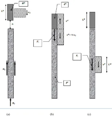
In the first moment, it is only compressed at the ram-pile interface when a pile is
struck by hammer. This compressed zone, or force pulse, as shown in Figure 4-1,
expands into the pile toward the pile toe at a constant wave speed, C, which
depends on the pile’s elastic modulus and mass density (or specific weight).
When the force pulse reaches the embedded portion of the pile, its amplitude is
reduced by the action of static and dynamic soil resistance forces. Depending on
the magnitude of the soil resistances along the pile shaft and at the pile toe, the
force pulse will generate either a tensile or a compressive force pulse which
travels back to the pile head. Both incident and reflected force pulses will cause
a pile toe motion and produce a permanent pile set if their combined energy and
force are sufficient to overcome the static and dynamic resistance effects of the
UNIVERSITY OF SOUTHERN QUEENSLAND DYNAMIC ANALYSIS BY WAVE EQUATION
[image:50.595.137.496.113.489.2]
(a) (b) (c)
Figure 4-1 – Definition of parameters governing stress wave propagation in piles
Resource: K. Rainer Massarsch, (2008), Ground Vibrations Induced by Impact Pile Driving,
Case Histories in Geotechnical Engineering, Arlington, VA
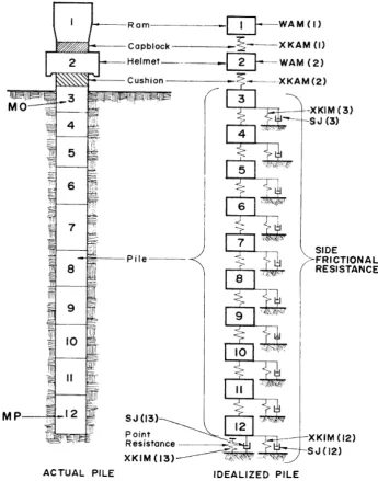
4.3 - Wave equation methodology
In a wave equation analysis, the hammer, helmet, and pile are modeled by a
series of segments each consisting of a concentrated mass and a weightless
spring. The hammer and pile segments are approximately one meter in length.
UNIVERSITY OF SOUTHERN QUEENSLAND DYNAMIC ANALYSIS BY WAVE EQUATION
expense of longer times to generate the result. Spring stiffnesses are calculated
from the cross sectional area and modulus of elasticity of the corresponding to
pile section. Hammer and pile cushions are represented by additional springs
which the stiffnesses are calculated from area, modulus of elasticity, and
thickness of the cushion materials. In addition, coefficients of restitution (COR)
are usually specified to model energy losses in cushion materials, and in all
segments which can separate from their neighboring segments by a certain
distance. The COR is equal to an elastic collision which preserves all energy and
is equal to zero for a plastic condition which loses all deformation energy.
Partially elastic collisions are modeled with an intermediate COR value.
The soil resistance along the embedded portion of the pile and at the pile toe is
represented by both static and dynamic components. Therefore, both a static and
a dynamic soil resistance force acts on every embedded pile segment. The static
soil resistance forces are modeled by elasto-plastic springs and the dynamic soil
resistance by linear viscous dashpots. The displacement at which the soil
changes from elastic to plastic behavior is referred to as the soil “quake”. In the
smith damping model, the dynamic soil resistance is proportional to a damping
factor times the pile velocity times the assigned static soil resistance. A
schematic of the wave equation hammer-pile-soil model is presented in Figure
UNIVERSITY OF SOUTHERN QUEENSLAND DYNAMIC ANALYSIS BY WAVE EQUATION
[image:52.595.145.491.109.549.2]
Figure 4-2 – Typical Wave Equation Model
Resource: Dr. Lee L. Lowery., P.E. Pile Driving Analysis By the Wave Equation, Department of
Civil Engineering Texas A & M University College Station, Texas
As the analysis commences, a calculated or assumed ultimate capacity, Rut, from
user specified values is distributed according to user input among the
UNIVERSITY OF SOUTHERN QUEENSLAND DYNAMIC ANALYSIS BY WAVE EQUATION
are assigned to shaft and toe to represent the dynamic soil resistance. The
analysis then proceeds by calculating a ram velocity using the input hammer
efficiency and stroke. The ram movement causes displacements of helmet and
pile head springs, and therefore compressions and related forces acting at the top
and bottom of the segments. Furthermore, the movement of a pile segment
causes soil resistance forces. A summation of all forces acting on a segment,
divided by its mass, produces the acceleration of the segment. The product of
acceleration and time summed over time is the segment velocity. The velocity
multiplied by the time step generates a change of segment displacement which
results in new spring forces. These forces divided by the pile cross sectional area
at the corresponding section equal the stress at that point.
Similar calculations are made for each segment until the accelerations, velocities
and displacements of all segments have been calculated during the time step.
The analysis then repeats for the next time step using the updated motion of the
segments from the previous time step. From this process, the accelerations,
velocities, displacements, forces and stresses of each segment are computed over
time. Additional time steps are analyzed until the pile toe begins to rebound.
The permanent set in millimeter unit of the pile toe is calculated by subtracting a
weighted average of the shaft and toe quakes from the maximum pile toe
UNIVERSITY OF SOUTHERN QUEENSLAND DYNAMIC ANALYSIS BY WAVE EQUATION
count) in blows per meter that corresponds to the input ultimate capacity. By
performing wave equation analyses over a wide range of ultimate capacities, a
curve or “bearing graph” can be plotted which relates ultimate capacity to
driving resistance.
A wave equation bearing graph is basically different from a similar graph
generated from a dynamic formula. The wave equation bearing graph is
associated with a single driving system, hammer stroke, pile type, soil profile,
and a particular pile length. If any one of the above items is changed, the bearing
graph will also change. Furthermore, wave equation bearing graphs also include
the maxima of calculated compression and tension stresses.
4.4 - Wave equation applications
A bearing graph provides the wave equation analyst with two types of
information:
z It establishes a relationship between ultimate capacity and driving
resistance. From the user’s input data on the shaft and toe bearing
resistances, the analysis estimates the permanent set (mm/blow) under one
hammer blow. Specifying up to ten ultimate capacity values provides a
relationship between ultimate capacity and driving resistance (or blow
UNIVERSITY OF SOUTHERN QUEENSLAND DYNAMIC ANALYSIS BY WAVE EQUATION
z The analysis also relates driving stresses in the pile to pile driving
resistance.
The user usually develops a bearing graph or an inspector’s chart for different
pile lengths and uses these graphs in the field, with the observed driving
resistance, to determine when the pile has been driven sufficiently for the
required bearing capacity.
In the design stage, the foundation engineer should select typical pile types and
driving equipment known to be locally available. Then by applying the wave
equation analysis with various equipment and pile size combinations, it becomes
possible to rationally:
z Design the pile section for drivability to the required depth and/or capacity.
For example, considerations of soft layers may make it necessary to drive
a pile through hard layers which driving resistance exceeds the resistance
expected at final penetration. A thin walled pipe pile may have been
initially chosen during design. However when this section is checked for
drivability, the wave equation analysis may indicate that even the largest
hammers will not be able to drive the pipe pile to the required depth
UNIVERSITY OF SOUTHERN QUEENSLAND DYNAMIC ANALYSIS BY WAVE EQUATION
thickness greater than necessary to carry the design load has to be chosen
for drivability considerations.
z Assist in the selection of pile materials properties to be specified based on
available driving stresses in reaching penetration and/or capacity
requirements.
In the above example, it is supposed that it will be possible to drive the
thinner walled pile to the desired depth but with excessive driving stresses.
More buffers or reducing hammer energy will lower the stresses but will
result in a refusal driving resistance. Choosing a high strength of steel
grade can solve this problem. For concrete piles, higher concrete strength
and/or higher prestress levels may provide acceptable solutions.
z Support the decision for a new penetration depth, design load, and/or
different number of piles.
In the above example, after it has been determined that the pile section or
its material strength had to be increased to satisfy pile penetration
requirements, it may have become available to increase the design load of
each pile and to reduce the total number of piles. Obviously, these
considerations will require reviewing geotechnical and/or structural
UNIVERSITY OF SOUTHERN QUEENSLAND DYNAMIC ANALYSIS BY WAVE EQUATION
Once the project has reached the construction stage, additional wave equation
analyses shall be performed on the actual driving equipment by:
z Construction engineers – for hammer approval and cushion design.
The pile type, material, and pile penetration requirements have been
selected by the foundation designer, the hammer size and hammer type
may have a decisive influence on driving stresses. For example, a hammer
with adjustable stroke or fuel pump setting may have the ability to drive a
concrete pile through a hard layer while allowing for reduced stroke
heights and tension stress control when penetrating soft soil layers.
Cushions are often chosen to reduce driving stresses. However, softer
cushions absorb and distribute larger amounts of energy and thus