THE APPLICATION OF MICROWAVE
SENSING TO THE MEASUREMENT OF
CHEESE CURD MOISTURE
A dissertation submitted by
Brendan Horsfield, BEng (Hons)
for the award of
Doctor of Philosophy
There is a need in the dairy industry for instrumentation capable of providing on-line
infor-mation about the moisture content of cheese during manufacture. Present measurement
tech-niques are usually performed off-line and can be susceptible to human error. It is demonstrated
that microwave-based moisture sensing techniques offer a number of potential advantages over
conventional methods due to the strong interaction of microwaves with water.
The permittivity of cream cheese curd and low-fat cheddar cheese curd has been measured over
a range of frequencies and moisture contents in order to establish the relationship between these
variables. A vector reflection coefficient measurement engine based on a six-port reflectometer
has been built and tested. A suitable sensing head has been fabricated from a short length
of microstrip transmission line. Two sensor characterisation models have been developed and
compared with measured data.
A novel algorithm has been developed to resolve the ambiguity inherent in many
permittiv-ity measurement techniques. It has been discovered that surface waves can propagate on a
grounded dielectric slab covered by a material with a higher dielectric constant, provided the
loss factor of the covering medium is greater than zero. It has also been found that the
domi-nant mode of microstrip can radiate when the line is covered by a high-permittivity material,
although this can be suppressed if the covering material is sufficiently lossy.
There are three principal conclusions to draw from the investigation in this thesis. Firstly,
changes in the moisture content of cheese curd during manufacture produce measurable
vari-ations in permittivity. Secondly, these changes can be measured accurately and cheaply using
off-the-shelf microwave hardware. Finally, considerable attention must be paid to the
dominant modes and higher order modes have not been fully resolved and would repay further
theoretical analysis.
I certify that the ideas, experimental work, results, analyses, software and conclusions reported
in this dissertation are entirely my own effort, except where otherwise acknowledged. I also
certify that the work is original and has not been previously submitted for any other award,
except where otherwise acknowledged.
Signature of Candidate Date
ENDORSEMENT
Signature of Supervisor/s Date
Date
This project has benefited at every stage from the assistance of many people. I wish to express
my gratitude to them for their contributions.
Firstly, I would like to thank my supervisors Dr Jim Ball and Dr Nigel Hancock for their
support and counsel throughout the course of this project. Both have achieved the difficult task
of providing sound guidance while at the same time giving me latitude to exercise my own
judgement concerning the scope and direction of the project.
I acknowledge the assistance of the technical support staff of the Faculty of Engineering and
Surveying, in particular Keith Fleming, Terry Byrne and Jim Scott. The workshop staff are
also owed a debt of thanks for their help in manufacturing the waveguide test cells used in the
permittivity survey.
The experimental phases of this project were helped by equipment loans from a number of
sources. Thanks are due to: Codan Queensland (formerly Mitec Limited) for the loan of
coaxial-to-waveguide adaptors and matched terminations; the Faculty of Applied Science (in
particular Ken Mottram and Victor Schultz) for the use of electronic scales and a travelling
microscope, and also for the donation of a range of test liquids; Telstra staff at Mt Lofty in
Toowoomba for the loan of a microwave frequency counter; and workshop staff in the USQ
soil testing laboratory for the loan of a temperature-controlled oven. Thanks also to Dr Marek
Bialkowski at the University of Queensland for the use of Ensemble and the HP Dielectric
Probe Kit.
In the course of this project I have consulted with several people having expert knowledge
in certain areas. In particular I wish to thank: Glen Exton from Hewlett Packard and the
aiding my understanding of the fundamentals of the spectral domain method.
I wish to express my gratitude to Tony Kilmartin at the Tatura dairy factory and Neil Bredhauer
at the Dairy Farmers factory in Toowoomba for their donations of samples of cheese curd. I
also appreciate the time they took out of their busy schedules to explain the cheese production
process to me and answer my questions.
I gratefully acknowledge the generous financial support provided by the Dairy Research and
Development Corporation and the University of Southern Queensland. Also deserving of
thanks are Ross Varnes at Codan Queensland for fabricating the microstrip and coplanar
waveg-uide sensors in his own time at no charge, and Dale Press at FasTrack Circuit Boards for etching
the frequency stabilisation PCB, also at no charge.
Finally, thanks to my partner Cathy for her love, support and patience throughout this long
endeavour.
Abstract ii
Certification of Dissertation iv
Acknowledgments v
List of Figures xvii
List of Tables xxv
Chapter 1 Introduction 1
1.1 Project Rationale . . . 1
1.2 Project Background . . . 2
1.3 Aim and Objectives . . . 3
1.4 Overview of Thesis . . . 3
1.5 Summary of Original Work . . . 6
1.6 Publications . . . 7
Part I Application of Microwave Sensing to Cheese Production 9 Chapter 2 Microwave Sensing 10 2.1 Introduction . . . 10
2.2.2 DC Conductivity . . . 13
2.2.3 The Debye Behaviour of Polar Materials . . . 14
2.2.4 Polar Liquids as Test Dielectrics . . . 15
2.3 Key Components of a Microwave Moisture Sensing Instrument . . . 17
2.4 Review of Microwave Moisture Sensing Techniques . . . 18
2.5 Advantages and Limitations of Microwave Sensing . . . 20
Chapter 3 Cheese Curd Permittivity Survey 22 3.1 Introduction . . . 22
3.2 Overview of Survey . . . 23
3.3 Equipment Setup . . . 23
3.3.1 Automatic Network Analyser . . . 23
3.3.2 Computer and GPIB Controller . . . 26
3.3.3 Waveguide Test Cells . . . 26
3.3.4 Dielectric Windows . . . 28
3.3.5 Temperature Controlled Oven . . . 30
3.4 Review of Permittivity Measurement Techniques . . . 31
3.4.1 The Transmission/Reflection (T/R) Method . . . 31
3.4.2 Multiple-Sample/Multiple-Position Methods . . . 32
3.4.3 Full Field Methods . . . 34
3.5 Calculation of Permittivity from Transmission Coefficient . . . 35
3.6 Initial Estimate . . . 37
3.7 Verification of Technique . . . 42
3.8.2 Cheddar Cheese Permittivity Measurements . . . 48
3.9 Conductivity Measurements . . . 51
3.10 Conclusion . . . 54
Chapter 4 Six-Port Reflectometer 56 4.1 Introduction . . . 56
4.2 Six-Port Fundamentals . . . 57
4.2.1 Theory of Operation . . . 57
4.2.2 Graphical Interpretation of Six-Port Operation . . . 59
4.2.3 Impact of Circle Locations on Performance . . . 61
4.2.4 Impact of Noise and Calibration Errors on Performance . . . 63
4.3 Calibration Procedure . . . 63
4.4 Transmission Measurements: The Dual Six-Port . . . 65
4.5 Review of Six-Port Applications . . . 65
4.6 Overview of Prototype Six-Port . . . 66
4.7 Six-Port Reflectometer Hardware . . . 68
4.7.1 Circuit Topology and Performance Characteristics . . . 68
4.7.2 Six-Port Implementation . . . 70
4.7.3 Calibration Standards . . . 70
4.8 YIG-Tuned Oscillator . . . 72
4.9 Frequency Stabilisation Circuit . . . 73
4.9.1 Oscillator Performance Limitations . . . 73
4.9.2 Prototype Stabilisation Circuit . . . 74
4.10.1 Benefits of Software Linearisation . . . 78
4.10.2 Linearisation Procedure . . . 79
4.10.3 Error Sources . . . 80
4.11 Sensor . . . 82
4.12 Data Acquisition Hardware . . . 83
4.12.1 Amplifier Board . . . 83
4.12.2 Data Acquisition Card . . . 84
4.13 Computer Controller . . . 85
4.14 Evaluation of System Performance . . . 87
4.15 Future Directions . . . 88
4.15.1 Improvements to Microwave Hardware . . . 88
4.15.2 Sensitivity to RFI/EMI . . . 88
4.15.3 Calibration Issues . . . 89
4.15.4 Protection Against Environmental Conditions . . . 89
4.15.5 Summary . . . 90
4.16 Conclusion . . . 90
Chapter 5 Microstrip Sensor Structures 92 5.1 Introduction . . . 92
5.2 Review of Alternative Sensor Types . . . 93
5.2.1 Reflection Sensors . . . 93
5.2.2 Transmission Sensors . . . 96
5.2.3 Resonant Sensors . . . 98
5.3.2 Coplanar Waveguide . . . 103
5.4 Prototype Moisture Sensors . . . 104
5.4.1 Microstrip Sensors . . . 105
5.4.2 Coplanar Waveguide Sensors . . . 107
5.5 Sensor Characterisation . . . 109
5.5.1 Empirical Characterisation . . . 110
5.5.2 Theoretical Characterisation . . . 110
5.5.3 Commercial Analysis Software . . . 111
5.5.4 Summary of Characterisation Philosophies . . . 112
5.6 Conclusion . . . 113
5.7 Summary: End of Part I . . . 114
Part II Propagation on Microstrip Line in Contact with Lossy, High Permittivity Material 116 Chapter 6 The Spectral Domain Method I: Static Approximation 117 6.1 Introduction . . . 117
6.2 Quasi-TEM Spectral Domain Method . . . 118
6.3 Derivation of Fourier Transformed Field Equations . . . 119
6.4 Basis Functions . . . 123
6.5 Solution Procedure . . . 125
6.6 Verification of Technique . . . 130
6.7 Performance Improvement Strategies . . . 132
Chapter 7 Surface Waves 135
7.1 Introduction . . . 135
7.2 Overview: Optical Analogy of Surface Waves . . . 136
7.3 Theory of Surface Waves . . . 138
7.4 Numerical Solution . . . 140
7.5 Spectral Domain Solution of Surface Wave Equations . . . 144
7.5.1 TM Surface Wave Modes . . . 144
7.5.2 TE Surface Wave Modes . . . 145
7.6 Leaky Wave Modes . . . 146
7.7 Conclusion . . . 147
Chapter 8 The Spectral Domain Method II: Full-Wave Analysis 148 8.1 Introduction . . . 148
8.2 Overview of Frequency-Dependent Phenomena . . . 149
8.2.1 Dispersion . . . 149
8.2.2 Surface Waves . . . 150
8.2.3 Radiation . . . 150
8.2.4 Leaky Dominant Modes . . . 150
8.2.5 Higher Order Modes . . . 150
8.3 Derivation of Fourier Transformed Field Equations . . . 151
8.4 Basis Functions . . . 157
8.5 Solution Procedure . . . 159
8.6 Dependence of Solution on Path of Integration . . . 161
8.8.1 Dual-Valued Parameters . . . 164
8.8.2 Spectral and Non-Spectral Regions of the Complex Plane . . . 165
8.8.3 Branch Cut Selection . . . 166
8.8.4 Closing Remarks . . . 171
8.9 Considerations in the Deformation of the Integration Contour . . . 172
8.9.1 Pole and Branch Point Migration . . . 172
8.9.2 Surface Wave Leakage Condition . . . 173
8.9.3 Radiation Leakage Condition . . . 175
8.10 Impact of Material Properties on Propagation . . . 177
8.11 Propagation Regimes of the EH Microstrip Mode . . . 177
8.11.1 Bound Regime . . . 177
8.11.2 Surface Wave Regime . . . 180
8.11.3 Radiation Regime . . . 183
8.12 Leaky Dominant Microstrip Modes . . . 187
8.13 Conclusion . . . 195
Chapter 9 Simulation of Sensor Scattering Parameters 198 9.1 Introduction . . . 198
9.2 Calculation of Microstrip Characteristic Impedance . . . 199
9.2.1 Definition of Microstrip Characteristic Impedance . . . 199
9.2.2 Calculation of Voltage on Strip Conductor . . . 200
9.2.3 Calculation of Total Strip Current . . . 201
9.2.4 Verification of Characteristic Impedance Formulation . . . 202
9.3.2 Equivalent Circuit Representation . . . 204
9.3.3 Calculation of Equivalent Circuit Component Values . . . 205
9.4 Calculation of Scattering Parameters . . . 208
9.5 Conclusion . . . 211
Chapter 10 Results 212 10.1 Introduction . . . 212
10.2 Dielectric Probe Measurements of Methanol Permittivity . . . 213
10.3 Comparison of Static and Full-Wave Models . . . 218
10.4 Comparison of Theory and Experiment (Launcher Mismatch Neglected) . . . 223
10.4.1 Static Model . . . 223
10.4.2 Full-Wave Model . . . 226
10.5 Comparison of Theory and Experiment (Launcher Mismatch Corrected) . . . 228
10.5.1 Launcher Admittance Function . . . 228
10.5.2 Static Model . . . 230
10.5.3 Full-Wave Model . . . 232
10.6 Conclusion . . . 234
Chapter 11 Discussion and Conclusions 235 11.1 Introduction . . . 235
11.2 Dielectric Properties of Cheese Curd . . . 236
11.3 Prototype Measurement Hardware . . . 236
11.4 Sensor Geometry . . . 237
11.6.1 Surface Wave Propagation on Microstrip Sensors . . . 239
11.6.2 Radiation Leakage . . . 239
11.6.3 Leaky Dominant Modes . . . 240
11.7 Simulation of Sensor S-Parameters . . . 240
11.8 Recommendations for Future Work . . . 241
11.8.1 Six-Port Reflectometer . . . 242
11.8.2 Propagation on Microstrip Covered by a High-Permittivity Half-Space 242 11.8.3 Sensor Design and Characterisation . . . 244
11.8.4 Cheese Curd Dielectric Model . . . 244
References 246 Appendix A Guide to Thesis Companion Disk 259 A.1 Chapter 3 Software . . . 260
A.2 Chapter 4 Software . . . 261
A.3 Chapter 6 Software . . . 262
A.4 Chapter 7 Software . . . 262
A.5 Chapter 8 Software . . . 263
A.6 Chapter 9 Software . . . 264
A.7 Softcopy of Dissertation . . . 264
Appendix B Cheddar Cheese Permittivity Measurements 265 Appendix C Circuit Schematics and PCB Artwork 268 C.1 Six-Port Reflectometer Power Supply Schematic . . . 268
Appendix D Derivation of TM Surface Wave Equations in the Spectral Domain 275
2.1 Plot of dielectric behaviour of distilled water at 25
C as a function of fre-quency, with
,
and
ps. . . 16
2.2 Plot of dielectric behaviour of methanol at 25
C as a function of frequency,
with
,
,
ps and !
!
. . . 17
2.3 Block diagram depicting major components of microwave moisture
mea-surement system. . . 18
3.1 Measurement setup used for permittivity survey. . . 24
3.2 Typical waveguide test cell for measuring permittivity of cheese curd. . . . 28
3.3 Three marker points used to obtain initial estimate of"# from phase of$&%('. 38
3.4 Measured and simulated permittivity of distilled water at 25
C. . . 43
3.5 Measured transmission coefficient $)%(' of Tatura cream cheese curd sample with 50.1% moisture content at a temperature of 79.4
C. Markers used to obtain permittivity estimate are shown as circles. Test cell is comprised of
a 25 mm length of WR90 waveguide. . . 45
3.6 Permittivity of Tatura cream cheese curd samples for a range of moisture
contents. . . 46
3.7 Graphs demonstrating sensitivity of calculated permittivity to perturbations in length of test cell (waveguide type = WR159, moisture content = 44.4%, temperature = 79.4
C). The true length of the test cell is 30 mm. . . 49
3.8 Complex permittivity vs moisture content for Tatura cream cheese curd at a frequency of 5.7 GHz (waveguide type = WR159, temperature * 80
C). Measured data is represented by small circles. The solid lines are the
least-squares lines of best fit to this data. . . 50
3.9 Exploded view of test cell used to measure ionic conductivity of cheese curd. 51
3.11 Conductivity vs moisture content for Tatura cream cheese curd at a temper-ature of 80
C. Measured data is represented by small circles. Solid line is
the least-squares regression curve of conductivity on moisture content. . . . 53
3.12 Conductivity of mozzarella curd measured at different stages in the
manu-facturing process. . . 53
4.1 Block diagram of a six-port reflectometer. + represents the vector reflection
coefficient of the unknown termination on Port 2. . . 58
4.2 Plot of six-port power ratio equations in the complex + -plane. Point of
intersection yields reflection coefficient +, of load on Port 2. . . 60
4.3 Practical implementation of a six-port reflectometer, including oscillator, frequency stabilisation circuit, six-port network, sensor, I/O subsystem, and
PC. . . 67
4.4 Schematic of six-port circuit used in prototype moisture sensing instrument. 68
4.5 Phase of reflection coefficients of six-port calibration standards vs frequency. 71
4.6 Measured tuning characteristic of AV7224-9 YIG-tuned oscillator at two operating temperatures. ‘COLD’ denotes the temperature of the oscillator at start-up. ‘WARM’ denotes the temperature of the oscillator at equilib-rium (approx 50
C). . . 74
4.7 Schematic of frequency stabilisation circuit. . . 75
4.8 Standing wave magnitude vs frequency as measured by frequency stabili-sation circuit. ‘COLD’ denotes the temperature of the oscillator at start-up. ‘WARM’ denotes the temperature of the oscillator at equilibrium (approx 50
C). . . 76
4.9 Standing wave magnitude vs D/A output word as measured by frequency stabilisation circuit. ‘COLD’ denotes the temperature of the oscillator at start-up. ‘WARM’ denotes the temperature of the oscillator at equilibrium (approx 50
C). . . 77
4.10 Relative error of frequency stabilisation circuit vs frequency. . . 77
4.11 Relative error of frequency stabilisation circuit vs frequency measured at
regular intervals over a one hour period. . . 78
4.13 Output voltage vs input power for a Wiltron 73N50 diode detector. . . 81
4.14 Sensitivity of Wiltron 73N50 diode detector vs input power. . . 81
4.15 Output screen comparing true and estimated values of reflection coefficient as measured by a simulated six-port. . . 86
4.16 Schematic for proposed self-calibrating six-port reflectometer. . . 90
5.1 Example of a planar transmission sensor. . . 102
5.2 Microstrip transmission line. . . 103
5.3 Coplanar waveguide transmission line. . . 104
5.4 91- microstrip moisture sensor. Scale of photograph is approximately 48 times true size. . ! mm,/021 mm,'3415! . . . 106
5.5 Underetched section of 56- microstrip moisture sensor. Scale of photo-graph is approximately 48 times true size. . 2! mm,/671 mm, '8215! . . . 107
5.6 63- coplanar waveguide moisture sensor. Scale of photograph is approx-imately 46 times true size. . 9! mm, :'6;:%<9! mm, /= 1 mm,'3415! . . . 108
5.7 76- coplanar waveguide moisture sensor with overetched section. Scale of photograph is approximately 46 times true size. . ! mm,:>'?:%@ ! >1 mm,/A41 mm,'8215! . . . 109
5.8 76- coplanar waveguide moisture sensor with broken track. Scale of pho-tograph is approximately 46 times true size. . B! mm,:>'AC:%D ! >1 mm,/A41 mm,'8215! . . . 110
6.1 Microstrip transmission line covered by lossy medium of infinite extent. . . 119
6.2 Theoretical charge distribution on microstrip conductor. Substrate and strip conductor included on plot for comparison. . . 124
6.3 Comparison of microstrip EGF as predicted by quasi-TEM model with pub-lished data. (Pubpub-lished data denoted by small circles.) . . . 131
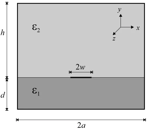
7.1 Grounded dielectric slab covered by superstrate of infinite extent. . . 137
7.2 Propagation path of a wave beam incident on a grounded dielectric slab. . . 137
7.3 I J vs""
% for TM , TE
' and TM' surface wave modes on grounded dielectric slab covered by lossy medium of infinite extent (>'KL15!
, "
%
M1 ,
/041
mm). No propagation is possible in shaded region. . . 141
7.4 N O and PQN O vs frequency for TM surface wave mode on grounded dielectric slab covered by methanol ('3415!
,/041
mm,R
C). . 142
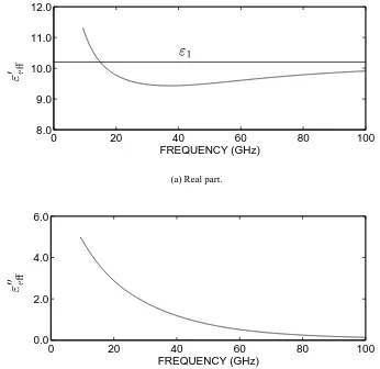
7.5 Effective permittivity vs frequency for TM surface wave mode on a grounded dielectric slab covered by a high-dielectric constant material ('6S15!
,
%T21VU<W ,/041
mm). . . 143
8.1 Cross section of shielded microstrip transmission line. . . 152
8.2 Approximate distributions of longitudinal and transverse current
compo-nents on a perfectly conducting strip. . . 157
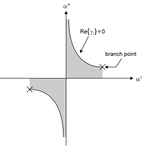
8.3 Plot showing the boundary between the spectral and nonspectral regions of
the complex -plane. Shaded areas denote nonspectral regions. . . 167
8.4 Path of integration taken when bypassing surface wave pole and branch
point with Sommerfeld branch cut. . . 168
8.5 Alternative path of integration which bypasses branch point by crossing
branch cut. . . 169
8.6 Graphic representation of the Grimm-Nyquist branch cut and the deformed integration contour. Shaded area denotes nonspectral region of complex
plane. . . 170
8.7 Migration of branch point and surface wave poles as""
% changes from high
loss to low loss. . . 173
8.8 Plot of magnitudes of integrands as a function of for microstrip having
'8215!
, %X41 , /A41
mm, . !
mm and IY
GHz. . . 179
8.9 Path of migration of TM surface wave pole and branch point for air-covered microstrip as loss of covering medium varies. Circle and cross denote pole and branch point respectively when ""
%
! . . . 179
8.11 Migration of TM surface wave pole with respect to superstrate loss for microstrip covered by a high-permittivity material. (>'@Z15!
U[W! , "
%
1 , /\1 mm, . ]! mm, I^
GHz. Circle denotes pole
location where TM mode is cutoff.) . . . 181
8.12 Normalised attenuation and phase coefficients of microstrip covered by a lossy, high-permittivity material. ('6S15!
UKW! , %_S10UKW
, /` 1 mm, . !
mm.) . . . 182
8.13 Migration of TM surface wave pole and branch point with respect to fre-quency for microstrip covered by a lossy, high-permittivity material. (a'3
15!
UbW! , %c71dUbW
, /671 mm, . 4!
mm. Circle denotes
pole location where TM mode is cutoff.) . . . 183
8.14 Migration of branch point with respect to superstrate loss for microstrip covered by a material with a dielectric constant greater than that of the substrate. ('YS15!
UKW! , "
%
]1 , /=]1 mm, . e! mm, I_
GHz. Cross denotes branch point location when ""
%
! .) . . . 185
8.15 Normalised attenuation and phase coefficients of microstrip covered by a lossless, high-permittivity material. ('fB15!
UbW! , %cB1cUbW! , /6
1
mm, . !
mm.) . . . 186
8.16 Normalised attenuation and phase coefficients of microstrip covered by a high-permittivity material with moderate loss. (>'gh15!
UiW! , %K
1VU<Wa1 , /041
mm, . !
mm.) . . . 188
8.17 Normalised attenuation and phase coefficients of microstrip covered by a high-permittivity material with high loss. (>'XZ15!
UjW! , %VZ1VUjW
, /041 mm, . !
mm.) . . . 189
8.18 Plot of branch point locus for different values of superstrate loss as fre-quency varies from DC to 60 GHz. (' k15!
UiW! , "
%
h1 , /l
1
mm, . !
mm.) . . . 190
8.19 Paths of integration yielding alternative dominant microstrip modes. . . 191
8.20 Normalised attenuation and phase coefficients of conventional and leaky EH modes of microstrip covered by a lossless, high-permittivity material. ('8415!
U<W! , %X !VU[W! , /A41
mm, . !
mm.) . . . 193
8.21 Normalised attenuation and phase coefficients of leaky EH mode of mi-crostrip covered by distilled water. ('mn15!
UW! , /n1
mm, .
!
mm,RpoaqsrEut
C.) . . . 194
alent circuit representation. . . 204
9.3 Cross-section of microstrip sensor with partitions inserted to isolate
launch-ers from material under test. . . 206
9.4 Two-port network with voltages and currents at each port. . . 209
10.1 Permittivity of methanol at 25
C as measured by HP8510 Automatic
Net-work Analyser equipped with Dielectric Probe Kit. . . 214
10.2 Static and infinite frequency permittivity of methanol vs frequency as
cal-culated from data from HP Dielectric Probe. . . 216
10.3 Permittivity of methanol at 25
C as measured by HP Dielectric Probe Kit. Dashed curves denote Debye functions generated using constants estimated
from measured data. . . 217
10.4 Normalised attenuation and phase coefficients of methanol-covered micro-strip as predicted by static and full-wave models. (>'915!
UgW! , /
1
mm, . !
mm, R&vErxw
1
1
C.) . . . 218
10.5 Migration of TM surface wave pole and branch point with respect to fre-quency for microstrip covered by methanol. ('3415!
U8W! , /A41
mm, .
!
mm, RyvErxw
1
1
C. Circle denotes pole location where TM
mode is cutoff.) . . . 219
10.6 Characteristic impedance of methanol-covered microstrip as predicted by static and full-wave models. ('gk15!
UiW! , /lk1 mm, . ! mm, RyvE rxw 1 1
C.) . . . 220
10.7 $)'z' of methanol-covered microstrip as predicted by static and full-wave models. Temperature of methanol assumed to be 21.1
C. No correction is
made for mismatch caused by launchers. . . 221
10.8 $y%(' of methanol-covered microstrip as predicted by static and full-wave models. Temperature of methanol assumed to be 21.1
C. No correction is
made for mismatch caused by launchers. . . 222
10.9 Comparison of measured $Q'z' of methanol-covered microstrip with value predicted by quasi-TEM theoretical model. Temperature of methanol is 21.1
C. Model makes no correction for mismatch caused by launchers. . . . 224
10.11 Comparison of measured $Q'z' of methanol-covered microstrip with value predicted by full-wave theoretical model. Temperature of methanol is 21.1
C. Model makes no correction for mismatch caused by launchers. . . 226
10.12 Comparison of measured ${%(' of methanol-covered microstrip with value predicted by full-wave theoretical model. Temperature of methanol is 21.1
C. Model makes no correction for mismatch caused by launchers. . . 227
10.13 Equivalent shunt components required to minimise the difference between measured and simulated scattering parameters of microstrip sensor. Tem-perature of methanol sample is 21.1
C. . . 229
10.14 Comparison of measured $Q'z' of methanol-covered microstrip with quasi-TEM model, with equivalent circuit parameters chosen to minimise the dif-ference between measured and simulated S-parameters. Temperature of methanol sample is 21.1
C. . . 230
10.15 Comparison of measured ${%(' of methanol-covered microstrip with quasi-TEM model, with equivalent circuit parameters chosen to minimise the dif-ference between measured and simulated S-parameters. Temperature of methanol sample is 21.1
C. . . 231
10.16 Comparison of measured $Q'z' of methanol-covered microstrip with full-wave model, with equivalent circuit parameters chosen to minimise the difference between measured and simulated S-parameters. Temperature of methanol sample is 21.1
C. . . 232
10.17 Comparison of measured ${%(' of methanol-covered microstrip with full-wave model, with equivalent circuit parameters chosen to minimise the difference between measured and simulated S-parameters. Temperature of methanol sample is 21.1
C. . . 233
B.1 Permittivity of low-fat cheddar cheese curd with no additional salt added. Measurements were performed at the production temperature of 36
C. . . . 266
B.2 Permittivity of low-fat cheddar cheese curd after the addition of extra salt. Measurements were performed at the production temperature of 32–34
C. . 267
C.1 Schematic of power supply on six-port reflectometer amplifier board. . . 269
C.2 PCB artwork for amplifier board (copper layer). . . 271
C.3 PCB artwork for amplifier board (component layer). . . 272
3.1 Cutoff frequencies for first and second propagating modes in waveguide
test cells. . . 26
3.2 Lengths of waveguide test cells used in cheese curd permittivity survey. . . 27
3.3 Guidelines for rounding off|}% for all possible $&%(' marker phases. . . 41
3.4 Initial estimates of the permittivity of several moist materials as calculated by permittivity estimation algorithm. More accurate values of permittivity
obtained using Newton’s Method are included for comparison. . . 41
3.5 $y%(' marker values for cream cheese curd sample with 50.1% moisture content. 44
4.1 Electrical lengths of offset short circuit calibration standards as measured
by HP-8720C Automatic Network Analyser. . . 71
5.1 Details of microstrip moisture sensors. All characteristic impedances have been estimated by static spectral domain analysis (see Sections 6.3–6.5 for
details). . . 105
5.2 Details of coplanar waveguide moisture sensors. All characteristic
imped-ances have been estimated using static spectral domain analysis. . . 107
6.1 Details of microstrip simulations used to verify correct operation of
quasi-TEM software. . . 130
7.1 Comparison of numerical values for TM cutoff frequency with estimates from Equation 7.9 for'3415!
,"
%
41 ,/041
mm. . . 140
8.1 Details of microstrip simulation used to verify correct operation of
full-wave software. . . 180
Introduction
1.1
Project Rationale
The moisture content of cheese curd during manufacture is a critical parameter which impacts
on both the quality and cost of the final product. At present moisture content is determined by
simple weighing and drying methods which, while accurate, are slow and do not lend
them-selves well to automation. Hence there is a need in the dairy industry for instrumentation which
can provide accurate moisture information in real time.
Microwave methods of moisture measurement offer an attractive means of achieving this
ob-jective. Due to its polar nature, the water molecule interacts very strongly with electromagnetic
waves at microwave frequencies. As a result the dielectric behaviour of moist materials at
mi-crowave frequencies should be a strong function of moisture content. In principle it should
be possible to design an instrument which exploits this characteristic. However, the practical
hurdles to be overcome in designing such an instrument make this a formidable task.
Firstly, measurement hardware is required which can accurately and repeatably measure the
reflection and/or transmission properties of a sensor embedded in a sample of cheese curd.
Computer control of this hardware is required if the instrument is to be automated.
Secondly, a suitable sensing head is required to interface the instrument to the material under
test. The type of sensor chosen must be appropriate for the measurand of interest, and must
provide adequate sensitivity to changes in moisture content while not exceeding the dynamic
range of the instrument.
Finally, the behaviour of the sensor must be adequately characterised so that measured
reflec-tion/transmission data can be mapped to the desired material property.
This thesis presents research progress towards the design of a prototype moisture sensing
in-strument. It is demonstrated that a future instrument will be based upon the above three
func-tional building blocks, namely a microwave measurement engine, a sensing head and a sensor
model.
1.2
Project Background
This work had its genesis as a two-year project funded by the Dairy Research and Development
Corporation (DRDC). The objective was to design and build a low-cost microwave-based
moisture sensing instrument for the cheese industry. The present author commenced work on
the project in mid-1994 at the University of Southern Queensland.
During this two-year period the basic assumptions concerning the theory of operation of the
instrument were shown to be valid. Specifically, the dependence of cheese curd permittivity on
moisture content was demonstrated experimentally, and the concept of an accurate, low cost
instrument to exploit this characteristic was shown to be feasible. However, it also became
clear that further, basic research was required in the area of sensor design and characterisation
before the instrument could function as hoped.
Thus, at the end of the DRDC-funded phase of the project, the present author commenced
work on a model of the instrument’s sensing head. Although this work involved a protracted
theoretical analysis, it was considered sufficiently important to the accurate operation of the
instrument to justify the time and effort. As such, the focus of the second half of the project
1.3
Aim and Objectives
The broad aim of this project was to demonstrate the feasibility of using microwave sensing to
perform online measurement of the moisture content of cheese curd during manufacture.
The specific objectives of this project were then determined as follows:
1. To perform an initial permittivity survey of a variety of cheese types in order to establish
the extent to which the dielectric properties of cheese curd are dependent upon moisture
content.
2. To design and fabricate low-cost microwave hardware which enables the reflection and/or
transmission coefficient of a sensor in contact with a sample of curd to be measured in
real time.
3. To develop an accurate theoretical model of a microstrip contact sensor which enables
the permittivity of a test material to be deduced from the measured scattering parameters
of the sensor.
1.4
Overview of Thesis
The dual emphasis of this project—namely, hardware development and sensor modelling—
suggested that a two-part thesis format was appropriate. Consequently, the end of this chapter
marks the beginning of Part I, which spans Chapters 2 to 5 and is concerned mainly with an
investigation of the dielectric properties of cheese curd, and the development of reflection
co-efficient measurement hardware. Part II spans Chapters 6 to 10, and describes the development
of a theoretical model of the instrument’s sensing head. The final chapter of the thesis then
draws together the results of Parts I and II, and discusses the significance of these results in the
context of the wider body of knowledge in the field.
Chapter 1 – Introduction
Chapter 1 introduces the proposition driving this project, namely that it is possible to measure
the moisture content of cheese curd accurately and cheaply by microwave sensing, given
intel-ligent instrument design. Chapter 1 also outlines the objectives and scope of the project, and
highlights those areas in which original work has been performed.
Chapter 2 – Microwave Sensing
Chapter 2 explains the theoretical background to microwave moisture sensing. Some
perti-nent examples of previous applications of this theory are reviewed, and the relative merits of
microwave-based techniques are summarised.
Chapter 3 – Cheese Curd Permittivity Survey
Chapter 3 is concerned with a survey of the electromagnetic properties of a variety of cheese
types. This was designed to establish the extent to which dielectric behaviour is affected by
such parameters as frequency, moisture content and salt content.
Chapter 4 – Six-Port Reflectometer
Chapter 4 describes the development and testing of a computer-controlled six-port
reflectome-ter. This instrument was the measurement engine with which the reflection coefficient of cheese
curd samples was to be monitored.
Chapter 5 – Microstrip Sensor Structures
Chapter 5 introduces the family of planar sensors which are analysed in detail in later chapters.
The strengths and limitations of these structures are explored, and the need for an accurate
Chapter 6 – The Spectral Domain Method I: Static Approximation
Chapter 6 presents a static analysis of the sensor family introduced in Chapter 5. The analysis
technique employed here is a popular one that has been used frequently in the past, however it
will be shown in later chapters that this method has some shortcomings which limit its
useful-ness as a sensor with high permittivity measurands.
Chapter 7 – Surface Waves
Chapter 7 investigates the conditions necessary for surface wave propagation on the sensor
structure. The effects of placing the sensor in contact with a high-permittivity, lossy dielectric
are investigated, with somewhat surprising and counterintuitive results.
Chapter 8 – The Spectral Domain Method II: Full-Wave Analysis
Chapter 8 follows on from Chapter 7 with a full-wave spectral domain analysis of the
sen-sor structure, taking into account signal loss due to surface wave leakage and radiation. The
presence of multiple dominant modes on the sensor structure is also investigated.
Chapter 9 – Simulation of Sensor Scattering Parameters
Chapter 9 brings together the work of previous chapters into a simulation of the scattering
parameters of a two-port sensor. While simple in principle, the analysis is made more difficult
by the need to account for the capacitance of the launchers at each end of the sensor.
Chapter 10 – Results
Chapter 10 compares and contrasts the theoretical sensor model with experimental results. The
superiority of the full-wave analysis over the static analysis is demonstrated, and the limitations
Chapter 11 – Discussion and Conclusions
Chapter 11 brings together the results of the entire project and highlights their significance to
the state of the art. The chapter concludes with some suggestions for future avenues of research
in this field.
1.5
Summary of Original Work
In the course of this project original theory and techniques have arisen out of five areas. In two
cases the originality resides in the application of existing ideas to a new measurement task.
The application of existing waveguide-based techniques to the measurement of cheese curd
permittivity produced experimental data that was unique at that time. Similarly, the choice of
microstrip transmission lines as contact sensors for measuring the S-parameters of cheese curd
is also believed to be an original application.
Three novel theoretical results have also been produced. One provides a reliable means of
resolving the ambiguity inherent in waveguide permittivity measurement techniques. Another
provides an insight into the propagation of surface waves on a dielectric slab covered by a
lossy high-permittivity material of infinite extent. Original work has also been carried out in
the analysis of radiation leakage from the dominant mode of microstrip immersed in a
high-permittivity medium.
The areas of this project in which original work was performed are summarised below.
1. Broadband measurement of cheese curd permittivity.
2. Development of robust algorithm for calculating initial estimate of sample permittivity
for waveguide t measurements.
3. Use of microstrip transmission line as a contact sensor for cheese curd permittivity
mea-surement.
4. Analysis of surface wave propagation on a grounded dielectric slab immersed in a lossy,
5. Investigation into the conditions necessary for radiation leakage to occur from the
dom-inant mode of microstrip immersed in a lossy, high-permittivity medium.
1.6
Publications
Horsfield, B., Ball, J. A. R., Holmes, W. S., Green, A., Holdem, J. R., and Keam, R. B. (1996).
A technique for measuring cheese curd moisture in real time. In Proceedings of the 1996
Conference on Engineering in Agriculture and Food Processing, Gatton, Australia. (Paper No. SEAg 96/065).
Ball, J. A. R., Horsfield, B., Holdem, J. R., Keam, R. B., Holmes, W. S., and Green, A. (1996a).
Cheese curd permittivity and moisture measurement using a 6-port reflectometer. In
Proceed-ings of the 1996 Asia-Pacific Microwave Conference, New Delhi, India. (Session B5, Paper No. INV1).
Ball, J. A. R., Horsfield, B., Holdem, J. R., Keam, R. B., Holmes, W. S., and Green, A. (1996b).
On-line moisture measurement during cheese production. In Proceedings of the 1996
Confer-ence on Scientific and Industrial RF & Microwave Applications, Melbourne, Australia.
Ball, J. A. R. and Horsfield, B. (1998). Resolving ambiguity in broadband waveguide
permit-tivity measurements on moist materials. IEEE Transactions on Instrumentation and
Measure-ment, 47(2): 390–392.
Ku, H. S., Siores, E., Ball, J. A. R., and Horsfield, B. (1998). An important step in microwave
processing of materials: Permittivity measurements of thermoplastic composites at elevated
temperatures. In Proceedings of the 1998 Pacific Conference on Manufacturing, Brisbane,
Australia, pp. 68–73.
Ku, H. S., Ball, J. A. R., Siores, E., and Horsfield, B. (1999). Microwave processing and
Horsfield, B. and Ball, J. A. R. (2000). Surface wave propagation on a grounded dielectric
slab covered by a high-permittivity material. IEEE Microwave and Guided Wave Letters,
10(5): 171–173.
Ku, H. S., Horsfield, B., Ball, J. A. R., and Siores, E. (2001). Permittivity measurement of
thermoplastic composites at elevated temperature. Journal of Microwave Power and
Electro-magnetic Energy, 36(2): 101–111.
NOTES:
In the above publications by Ball, Horsfield, Holdem, Keam, Holmes and Green, the
candi-date’s contribution to the reported work was as follows: design of waveguide test cells and
dielectric windows; development of software to calculate permittivity of moist materials from
measured S-parameters; survey of permittivity and DC conductivity of a variety of cheese curd
types over a range of moisture contents; assembly of six-port reflectometer including frequency
stabilisation circuit; implementation of six-port reflectometer calibration & control routines in
C++; measurement of$Q'z' of microstrip knife sensor embedded in samples of cheese curd over
a range of moisture contents.
The candidate’s contribution to the publications by Ku, Siores, Ball and Horsfield was the
design of the WR90 and WR159 waveguide test cells, and the development of software to
Application of Microwave Sensing to
Microwave Sensing
2.1
Introduction
This chapter introduces the concept of microwave sensing, including theory, implementation
strategy, prior art and relative merit in comparison to other techniques.
The first section of this chapter provides an overview of the physical principles which
under-pin microwave-based sensing techniques. The key mechanisms which determine the dielectric
properties of a material are outlined, with particular attention to moist substances. The
di-electric behaviour of methanol is also examined, due to its usefulness as a test liquid with a
well-understood dielectric spectrum.
The second section identifies the major components which are required in implementing an
online, automated moisture sensing instrument. Such components include both the hardware
devices like the sensing head, and the software algorithms which perform control and
compu-tational functions.
The third section provides a brief review of some relevant past applications of microwave
moisture sensing. The relative merits of each approach are examined to assess their suitability
for cheese curd moisture measurement.
The final section of this chapter addresses an important implicit assumption in this thesis:
namely, that microwave-based approaches offer certain advantages over other, more
conven-tional methods. The benefits of microwave sensing are described, as well as some of the
po-tential limitations.
2.2
Microwave Sensing and the Dielectric Properties of Matter
Microwave measurement techniques exploit the interaction between electromagnetic waves
and matter.
The manner in which an electromagnetic field is altered by a material depends on a number
of macroscopic factors, including density, temperature, composition, and also upon the
mi-crostructure of the material. Strictly speaking, however, the propagation of electromagnetic
waves through a substance depends on only two fundamental parameters: the dielectric
per-mittivity , and the magnetic permeability~ of the substance.
For the purposes of this project it was assumed that all materials under consideration would be
nonmagnetic. This is not an unreasonable assumption. After all, the ultimate aim of the project
was to develop a sensor for the dairy industry, where all potential measurands are nonmagnetic.
Indeed, most solid and liquid materials in nature are nonmagnetic, so there is no great loss of
generality in taking this approach.
Thus, throughout this thesis the term ‘microwave sensing’ refers to the measurement of
dielec-tric properties only. Theoretical models assume a magnetic permeability of ~^9~ for all
materials, where~ is the permeability of free space. Additionally, the terms ‘permittivity’ and
‘complex permittivity’ are used interchangeably, while ‘dielectric constant’ and ‘loss factor’
denote the real and imaginary parts of permittivity respectively.
The following sections summarise the physical mechanisms which determine a material’s
2.2.1 Polarisation
The dielectric constant of a material is defined concisely by Hasted (1973, pp. 1–31) as ‘a
mea-sure of the extent to which the electric charge distribution in the material can be distorted 55
by the application of an electric field’. This distortion of charge is referred to as polarisation.
All matter can be polarised to a greater or lesser extent, regardless of whether the matter is
in a solid, liquid or gaseous state. (In keeping with the theme of the rest of this thesis, the
following discussion will apply to dense materials only, i.e. materials in the solid or liquid
phase.) Polarisation phenomena can express themselves in four different ways:
Electronic polarisation – Refers to the displacement of electrons in atoms relative to the
nu-cleus, resulting in an uneven distribution of charge in the atom.
Atomic polarisation – Closely related to electronic polarisation, this effect manifests itself as
the displacement of atoms within a molecule due to the uneven distribution of charge
inherent in the molecule.
Ionic polarisation – Materials containing isolated pools of free charge suspended in a
non-conducting background medium can become polarised under the influence of an applied
electric field. This phenomenon is also known as the Maxwell-Wagner effect (Nyfors
and Vainikainen, 1989, pp. 58–62).
Orientation polarisation – The most significant form of polarisation in biological materials
at microwave frequencies, this type of polarisation manifests itself as a torque-like force
which causes molecules to rotate in line with an applied electric field. This effect is
a consequence of uneven distribution of charge in the molecule, which results in the
molecule having a permanent dipole moment.
Of the four categories of polarisation, ionic and orientation polarisation are by far the most
significant in the microwave band. The dielectric properties of materials subject to these effects
can vary dramatically with frequency, temperature, and material composition.
Electronic and atomic polarisation only become significant at infrared and optical frequencies
2.2.2 DC Conductivity
If a material possesses a DC conductivity—due for example to the presence of ions—then this
will affect the dielectric properties of the material, particularly at low frequencies. The nature
of this effect can be predicted from Maxwell’s equations, specifically Amp`ere’s law, which
states:
CY
a (2.1)
where
is the magnetic field intensity, is the conduction-current density, and
is the
electric flux density.
Ohm’s law at a point states that[& , where is the DC conductivity of the medium, and
denotes the electric field intensity. The constitutive relations state that
t , where t is
the permittivity of the medium relative to the free-space permittivity . It is therefore possible
to re-write the right hand side of Equation 2.1 as follows:
a
&m
t
a (2.2)
Assuming harmonic time variation, differentiation in time becomes equivalent to multiplication
byW . Allowing the medium to be lossy (i.e. t "t U[W""
t ), Equation 2.2 becomes
a &mbW T
"
t
U[W "" t
(2.3)
from which it can be inferred that
t "
t
U[W ""
t
"
t
U[W
""
t
(2.4)
Thus, from Equation 2.4 it is evident that the impact of non-zero DC conductivity on the
per-mittivity of a material is to introduce an additional loss factor which varies inversely with
2.2.3 The Debye Behaviour of Polar Materials
As mentioned earlier, the dielectric properties of polar materials can vary considerably with
frequency. In the classical case, the permanent dipole moment of the molecule bestows a high
value of"t on the material at DC, decreasing as frequency increases to a much smaller high
frequency value. At the same time, the loss factor ""
t increases from a low value at DC, to a maximum at the so-called ‘relaxation frequency’. The peak value of the loss factor can be
relatively high at this frequency, due to the friction between molecules which acts to impede
their oscillation with the electric field. Above the relaxation frequency the loss gradually drops
to a low value again.
This variation of dielectric properties with frequency can be accurately described by the Debye
function, which has the following general form:
t
}Ug
1?bW
(2.5)
where t is the complex dielectric constant of the material, is the high-frequency
per-mittivity, is the static permittivity, and is the relaxation period. All of these parameters
have material-specific values, which are usually obtained empirically (Nyfors and Vainikainen,
1989, pp. 41–62).
Equation 2.5 is often separated into real and imaginary components, viz.:
"
t
)Ug
1?g
%
% (2.6)
""
t
}Ug
1?g
%
% (2.7)
In some materials, such as mixtures or aqueous solutions, it may not be possible to perfectly
describe the properties of the material with only a single relaxation frequency (Hasted, 1973,
pp. 1–31). In such situations a number of variations on the classical single-relaxation Debye
The simplest and most physically meaningful is the multiple component Debye spectrum,
which involves the summations of two or more Debye functions with different relaxation times:
t
}U 8'
1?bW '
8'Ug%
1bW 5%
55
Ug
1?jW
(2.8)
where is the relaxation period of the| rxw
component of the mixture, and is the height of
the| rxw
plateau above the baseline.
Two empirical variations of Equation 2.5 are often used (Nyfors and Vainikainen, 1989, pp. 41–
62). The first is known as the Cole-Cole equation, given by
t
}Ug
1?W
'z (2.9)
The second is known as the Cole-Davidson equation, given by
t
}Ug
1?bW
(2.10)
In both of these equations is an empirical constant which represents a distribution of
re-laxation times. In Equation 2.9 the distribution is symmetrical, whereas in Equation 2.10 the
distribution is asymmetrical (Hasted, 1973, pp. 1–31).
2.2.4 Polar Liquids as Test Dielectrics
An important step in the development of any instrument is experimental verification of correct
operation. This requires the use of a test material with known dielectric properties, preferably
of the same magnitude as the final measurand. Polar liquids are well suited to this role for
several reasons.
Firstly, the fact that polar materials can be well characterised by the Debye equation or one
of its variants means that their dielectric behaviour can be determined without the need for
Secondly, the use of polar liquids eliminates many of the problems caused by the non-ideal
characteristics of solid and semi-solid materials, such as heterogeneous composition and the
presence of air inclusions.
Finally, polar liquids are not biologically active, so their properties do not change with time.
They have no special storage requirements beyond those usually required for laboratory
chem-icals, whereas potential measurands like cheese curd usually require refrigeration.
A range of polar liquids was considered in the course of this project, including formamide,
ethanediol, ethanol, methanol and distilled water. The latter two were eventually selected for
use as test liquids, the others having the drawbacks of being either too flammable or being
emitters of toxic fumes and therefore requiring the use of a fume cupboard.
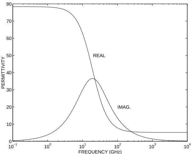
A plot of the complex permittivity of distilled water at 25
C is shown in Figure 2.1. This data
was generated using the classical Debye equation for distilled water with a single relaxation
time. Debye parameters were obtained using data from Kaatze (1989).
10−1 100 101 102 103 104 0
10 20 30 40 50 60 70 80
FREQUENCY (GHz)
PERMITTIVITY
[image:42.595.166.472.434.681.2]IMAG. REAL
Figure 2.1: Plot of dielectric behaviour of distilled water at 25 C as a function of
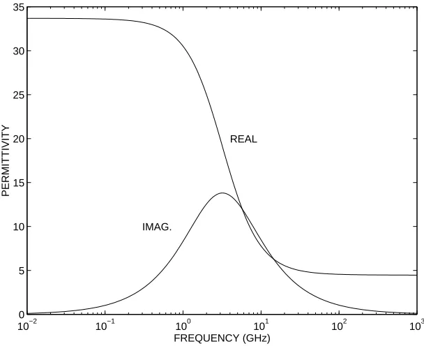
A plot of the complex permittivity of methanol at 25
C is shown in Figure 2.2. This data was
generated using the Cole-Cole equation with Debye parameters obtained from Jordan et al.
(1978).
10−2 10−1 100 101 102 103 0
5 10 15 20 25 30 35
FREQUENCY (GHz)
PERMITTIVITY
IMAG.
[image:43.595.167.471.191.439.2]REAL
Figure 2.2: Plot of dielectric behaviour of methanol at 25 C as a function of frequency,
with5{ ¨¨¢ ,¤b£¢£© ,§db£ª¢©ª ps and«6b¬¢¬¨© .
2.3
Key Components of a Microwave Moisture Sensing Instrument
It is envisaged that a successful curd moisture measurement system must consist of the
follow-ing key subsystems:
Computer Controller – Due to the numerically intensive nature of the software algorithms
which estimate curd moisture content, a microprocessor-based controller will be
neces-sary if the instrument is to make measurements in real time.
Microwave Hardware – Consists of a microwave network which is used to measure the
Sensor – Provides an interface between the instrument and the material under test. The sensor
transduces the physical properties of cheese curd (such as moisture content, temperature,
density etc) into an electrical signature which is dependent upon those properties.
Calibration Algorithm – Before the instrument can be used, it will have to be calibrated
against a set of known standards in order to account for imperfections in the microwave
hardware.
Sensor Model – A mathematical model which describes the electrical properties of the sensor
when it is placed in contact with a sample of curd.
Curd Model – Relates the dielectric properties of cheese curd to moisture content.
Display – Presents results in an appropriate format. This may imply a graphical display to
enable monitoring by staff. Alternatively, it may be more desirable to produce an output
voltage/current proportional to the moisture content, in order to implement a closed-loop
control strategy.
Figure 2.3 depicts the interconnections between these subsystems.
Figure 2.3: Block diagram depicting major components of microwave moisture measure-ment system.
2.4
Review of Microwave Moisture Sensing Techniques
A large number of microwave moisture sensing methods have been described in the literature.
Kudra et al. (1992) have measured the electromagnetic properties of milk at 2.45 GHz using
a single-mode active cavity. By measuring the change in the Q-factor of the cavity when
samples were placed in it, the permittivity of the samples could be calculated. This enabled
the quantities of several constituents of the samples to be estimated. As with all resonant
techniques, however, this approach only enables measurements to be made at one frequency.
Kent et al. (1993) have implemented a system which determines the water content of
concen-trated milk during the manufacture of dried milk products. The method entails the measurement
of power lost through a microstrip sensor which is placed in contact with the material under
test. Water content is estimated by referring to a family of calibration curves which can be
adjusted to compensate for temperature variation. The authors claim that changes in moisture
content of 0.5% may be detected using this system, provided use is restricted to materials
with moisture contents below 50%.
Three approaches have been demonstrated by Robinson and Bialkowski (1992) for estimating
the moisture content of beach sand by measuring the phase change of a signal transmitted
across a sample. Each method makes use of a quadrature mixer, and is contingent upon the
density of the sample being known.
Sabburg et al. (1992) have used a waveguide transmission technique to investigate the
relation-ship between permittivity and soil moisture for two Australian soils. A waveguide cell was
packed with moistened soil and the transmission coefficient measured using an HP8510
Au-tomatic Network Analyser. This data enabled a transcendental equation relating transmission
coefficient to sample permittivity to be solved numerically. The results of this work suggested
that the calibration curves built into some commercially available soil moisture measuring
in-struments are inaccurate.
A density-independent method of moisture determination has been explored by Meyer and
Schilz (1980). Transmission measurements were made in a waveguide sample container on
a range of materials, including tobacco, feathers and instant coffee. The measured data was
used to calculate the complex permittivity, which was then substituted into a function that
yielded a result dependent upon moisture content only. This method appeared to work well for
materials with low moisture contents (i.e. less than 30%), but became less and less sensitive to
2.5
Advantages and Limitations of Microwave Sensing
Before deciding to adopt a microwave-based approach for the measurement of material
prop-erties it is helpful to consider the relative merits of this technology.
There are undoubtedly some disadvantages associated with microwave measurement
tech-niques. For example, there is the relatively high expense of microwave sensing to consider,
which tends to increase as frequency increases (Nyfors and Vainikainen, 1989, pp. 28–39).
There is also the need for very careful, application-specific design of components like
sens-ing heads (Nyfors and Vainikainen, 1989, pp. 28–39). Additionally, the nontrivial problem of
instrument calibration must be addressed (Kress-Rogers, 1993, pp. 191–193).
However, in applications such as moisture measurement, microwave sensing has a number of
distinct advantages.
Firstly, microwave moisture sensing techniques can be very accurate, often more so than
con-ventional methods. This is because the dielectric permittivity of water at microwave
frequen-cies is much greater than that of biological substances like protein and fat (Kudra et al., 1992).
It is therefore the dominant contributor to the overall permittivity of materials like cheese curd,
which usually have high moisture contents.
Secondly, microwave sensing is non-hazardous, non-destructive and (depending on the sensor
type) non-invasive (Kraszewski, 1996, p. 20).
Thirdly, microwave sensing can be used to measure the bulk properties of a material.
Tech-niques such as infrared sensing only measure the surface properties of the material under test
(Kress-Rogers, 1993, pp. 191–193).
Fourthly, microwave measurements can yield information about other constituents besides
wa-ter. Previous work with milk (Kudra et al., 1992) has demonstrated that it possible to measure
protein, salt and fat content in addition to water content.
Finally, if a suitable microprocessor is used to acquire and process data from the microwave
pp. 28–39). This real-time measurement capability opens up the possibility of closed loop
control, whereby the moisture information from the instrument could be fed back into the
Cheese Curd Permittivity Survey
3.1
Introduction
A key phase in the development of a new instrument is gaining an understanding of the
mea-surand of interest. For a microwave moisture sensing instrument this means identifying those
parameters which affect the dielectric properties of cheese curd.
This chapter describes a series of experiments that were designed to establish the extent to
which curd permittivity is affected by variations in frequency, moisture content and salt content.
The first two sections provide an overview of a waveguide permittivity survey which was
con-ducted on a variety of curd types, including theoretical background, equipment setup and
exper-imental methodology. This is followed by a discussion of a permittivity estimation algorithm
which enabled dielectric information to be extracted from measured data. The fourth section
presents the results obtained for each curd type, while the fifth section describes the method by
which the ionic conductivity of different samples of curd was measured. The chapter concludes
with a summary of the findings of the cheese curd measurements and the implications for the
development of a moisture sensing instrument.
3.2
Overview of Survey
The technique for measuring cheese curd permittivity was based on work by Ness (1983; 1985)
and Sabburg et al. (1992). The method involved filling rectangular waveguide cells with
sam-ples of a test material and measuring the transmission coefficient with an Automatic Network
Analyser. In order to obtain dielectric information a transcendental equation relating
transmis-sion coefficient to permittivity was solved numerically.
A number of waveguide cells of varying sizes were constructed to give coverage of the
fre-quency range 2–12 GHz. Samples of cheese curd were mixed thoroughly prior to being placed
into the cells, which were kept in a temperature-stabilised oven at the production temperature.
The permittivity was then measured, and the corresponding moisture content determined by
weighing and drying the sample.
3.3
Equipment Setup
The equipment setup used for the permittivity survey is depicted in Figure 3.1, the details of
which are discussed below.
3.3.1 Automatic Network Analyser
All transmission coefficient measurements were made using a Hewlett Packard 8720C
Auto-matic Network Analyser (hereafter referred to as the 8720C). The frequency range covered by
the 8720C extends from 50 MHz to 20.05 GHz with a dynamic range of over 100 dB.
Prior to use the 8720C had to be calibrated to reduce the errors within the instrument, such as
source mismatch, imperfect isolation between ports of directional couplers, mismatch due to
an internal switch, and mismatch at the reference plane.
Conventional calibration methods for network analysers typically require a number of known
transmis-®A¯{°G±{²(³Q´µµ¶&±
·l¸p¹ ¶{º}¯{´±{¶
» ¶{¼½}®c¶}µµ ¾Y¿fÀÂÁm®dÃQĽs°uÃ}µµ¶}°
Å ¿?²Æ{ÇpÈ}É&®Ê¯a½ÃQË ¸ ½s´Ì
Í ¶p½ÏÎ0ÃQ°sÐcÊÄ ¸ µÑ¼¶Q° ¿3®
sion coefficients are then measured and entered into an error model of the network analyser.
This model is solved for a number of correction coefficients, which enable subsequent
mea-surements to be adjusted such that a much more accurate estimate of the scattering parameters
is obtained (Hewlett-Packard Corporation, 1992).
Different error models are possible for a given instrument. In general, the more accurately a
model represents the internal mismatches of an instrument, the more calibration standards are
required to determine the correction coefficients of the model. For example, the most accurate
calibration procedure available on the 8720C is the full two-port calibration. This requires as
calibration standards a short circuit termination, an open circuit termination and a matched
load. Furthermore, a number of measurements must be made with the two test ports of the
instrument connected together directly, or alternatively, connected together via a length of
low-loss transmission line.
A less accurate, but simpler, version of this procedure is the through-reflect-line or TRL*
(pro-nounced “TRL-star”) calibration method. This method requires as standards a short circuit OR
an open circuit, a low-loss length of line between ports one and two, and a direct connection
between the two ports. A variation on this method is the line-reflect-match or LRM* calibration
procedure, in which the low-loss transmission line is replaced with a matched termination.
During the course of the cheese curd permittivity survey, both the full two-port and LRM*
calibration procedures were evaluated. Due to the greater speed with which LRM* calibrations
could be performed, LRM* quickly became the preferred method.
In order to make accurate measurements using waveguide, the above procedures had to be
carried out using waveguide calibration standards. A problem arose, however, when trying
to implement an open circuited calibration standard. This was because an open waveguide
termination radiates energy, resulting in an input reflection coefficient magnitude of less than
unity. A phase shift is also induced in the reflected wave due to the effects of the fringing field,
which appears as a small terminating reactance (Hewlett-Packard Corporation, 1992). Rather
than attempt to account for these effects with a theoretical model, it was far easier to replace
the open circuit termination with a short circuit that was offset from the reference plane by a
All calibration standards except for the matched loads were custom-built at the University of
Southern Queensland. Due to the fact that the full two-port and LRM* calibration techniques
assumed perfectly conducting short circuit terminations and lossless walls, each calibration
standard had to be polished to as smooth a finish as possible, .
3.3.2 Computer and GPIB Controller
Two essential components of the broadband permittivity measurement process were the
com-puter and GPIB controller. These devices facilitated the automation of measurements and the
logging of data. When a measurement run was ready to commence the computer would trigger
a sweep on the 8720C. The user was then asked to place three markers spaced 90
apart on the
network analyser’s phase trace; these markers could later be used to calculate a starting
esti-mate of permittivity if one was not already available. The transmission coefficient data and the
three marker values were then downloaded to the computer’s hard drive, where post-processing
could take place to extract permittivity information.
3.3.3 Waveguide Test Cells
Test cells were manufactured in three different sizes of waveguide: WR90, WR159 and WR284.
These sizes were chosen because they provided good coverage of the frequency range from 2–
12 GHz. Table 3.1 lists the cutoff frequencies for the TE' and TE% modes in each waveguide
type.
Table 3.1: Cutoff frequencies for first and second propagating modes in waveguide test cells.