White Rose Research Online
[email protected]
Universities of Leeds, Sheffield and York
http://eprints.whiterose.ac.uk/
This is an author produced version of a paper published in
IEEE Transactions
on Ultrasonics, Ferroelectrics and Frequency Control.
White Rose Research Online URL for this paper:
http://eprints.whiterose.ac.uk/43678/
Paper:
Smith, PR, Cowell, DMJ, Raiton, B, Vo Ky, C and Freear, S (2012)
Ultrasound
array transmitter architecture with high timing resolution using embedded
phase-locked loops.
IEEE Transactions on Ultrasonics, Ferroelectrics and Frequency
Control, 59 (1). 40 - 49 (10).
Ultrasound Array Transmitter Architecture
With High Timing Resolution Using
Embedded Phase-Locked Loops
Peter R. Smith,
Student Member, IEEE,
David M. J. Cowell, Benjamin Raiton, Chau Vo Ky
and Steven Freear,
Senior Member, IEEE
Abstract—Coarse time quantization of delay profiles within ultrasound array systems can produce undesirable sidelobes in the radiated beam profile. The severity of these sidelobes is dependent upon the magnitude of phase quantization error - the deviation from ideal delay profiles to the achievable quantized case. This paper describes a method to improve inter channel delay accuracy without increasing system clock frequency by utilising embedded Phase-Locked Loop (PLL) components within commercial Field Programmable Gate Arrays (FPGAs). Precise delays are achieved by shifting the relative phases of embedded PLL output clocks in 208 ps steps. The described architecture can achieve the necessary inter element timing resolution required for driving ultrasound arrays up to 50 MHz. The applicability of the proposed method at higher frequencies is demonstrated by means of extrapolating experimental results obtained using a 5 MHz array transducer. Results indicate an increase in Transmit Dynamic Range (TDR) when using accurate delay profiles generated by the embedded PLL method described, as opposed to using delay profiles quantized to the system clock.
I. INTRODUCTION
A
N ultrasound array is a collection of independent ultra-sonic sources arranged in close proximity and excited in a pre-determined manner. Whilst the arrangement of these sources is often fixed, the nature of the transmitted beam can be altered dynamically using timing techniques. Such techniques are attractive as they enable a beam of acoustic pressure to be concentrated at a focal point, steered at an angle and/or swept across a region of interest using electronic means. This electronic timing is often referred to as phased array, as early implementations used phase differences to control the transmitted beam as opposed to time delays. Phased array ul-trasound is extensively used in both diagnostic and therapeutic medical applications as well as industrial applications such as non-destructive evaluation [1].Phased array techniques can be adopted at both the trans-mitter and the receiver. During reception, array sensitivity may be enhanced in a particular direction by synthetically forming a beam which may be steered and/or focused. Steering and focusing is achieved at the receiver by adding additional delays to incoming signals according to a phase delay profile.
Manuscript received June 13, 2011; accepted November 2, 2011. This work was supported by the Engineering and Physical Sciences Research Council (EPSRC).
The authors are with the Ultrasound Group, School of Electrical and Electronic Engineering, University of Leeds, Leeds, LS2 9JT, UK, e-mail: [email protected].
Digital Object Identifier 10.1109/TUFFC.2012.2154
In transmission, acoustic pressure beams can be steered and focused by applying phase delays between array elements to alter the time of each element’s excitation. The nature of the excitation sequence is defined according to a particular phase delay profile.
A linear phase delay profile with delay values increasing evenly from element to element will steer a non-focused or plane wave at an angle away from the array axis. A non-linear but parabolic phase delay profile focuses the beam towards a point. A combination of linear and a parabolic phase delay profiles permits both steering and focusing [2].
An ideal theoretical phase delay profile used in transmission or reception contains delays which can be precisely imple-mented. A quantized delay profile is an approximation of the ideal phase delay profile, with timing inaccuracy introduced as a result of hardware implementation. The deviation from the ideal phase delay profile is described as phase quantization error [3].
Large values of phase quantization error cause a number of undesired effects in the array beam profile [4] such as raised sidelobes which can subsequently degrade the performance of a diagnostic imaging system [5].
Whilst the unwanted effects of phase quantization may be reduced during receive processing with methods such as filter-ing and interpolation [6]; the performance of the transmitter is dependent on the resolution of the inter-element phase delays and thus the transmitter architecture.
A number of phased array transmitter architectures have been presented in previous literature. These methods vary from fixed solutions such as tapped analogue delay lines, to variable methods such as storage of signals and offsetting in memory [7]. Other variable delay methods include the use of dedicated integrated delay circuits and microcontrollers as discussed in [8], and the use of external Phase-Locked Loop (PLL) components within front-end designs [9].
gate delays within each delay circuit become more critical and become a potentially limiting factor.
An example of an integrated solution using phase shifted clocks was demonstrated by Hatfield [10]. This work focused on an Application Specific Integrated Circuit (ASIC) design intended to be incorporated within the transducer itself. A reported benefit of the design included reducing the unwieldy bundle of cables that accompany a transducer, which increases as imaging modalities increase in complexity. A main concern with this design however is the lack of transmit excitation flexibility, which may be necessary as ultrasound techniques evolve.
This paper discusses the concept of phase quantization error with respect to transmitter performance and presents a hardware implementation using PLL components embedded within Field Programmable Gate Arrays (FPGAs). These com-ponents are traditionally aimed to provide accurate high speed performance in communication and backplane designs. In this work these resources are used within an ultrasound phased array transmitter to improve inter-element phase resolution and maintain desired transmit dynamic range across frequency. The implementation described takes advantage of the increased flexibility and functionality within current FPGAs.
II. IMPACT OFDELAYQUANTIZATION ON THE
PERFORMANCE OFPHASEDARRAYS
Ultrasound array transducers are devices which package a collection of ultrasonic elements or sources arranged in close proximity. The design and form of an array transducer varies from application to application with elements arranged to facilitate a number of imaging or transmission modes.
A transducer composed of a single line of equally spaced elements is known as a 1-D linear periodic array transducer. The use of 1-D arrays with phased array techniques is com-monplace in diagnostic imaging and can be divided into two classes: phased-linear imaging and linear-phased imaging [11]. Phased-linear imaging uses sub-groups of elements (known as apertures) often focused to a depth to scan a linear region governed by the dimensions of the transducer. Linear-phased imaging typically uses all transducer elements to focus and steer a beam across an angular sector often wider than the probe itself.
A. Array Steering and Focusing
Steering or deflecting an unfocused plane wavefront at an angle other than broadside can be achieved by applying a linearly increasing delay profile across the array aperture. The delay between adjacent elements can be calculated [12] with
τn=
dsinθs
c (1)
where τn is the delay value for element n,d is the distance
between adjacent elements, c is the longitudinal velocity within the medium and θs is the steering angle (where 0◦
would be perpendicular to the array).
In order to create a focused beam at a point an axial distance away from the center of the array the delay profile can be calculated [11] with
τn =
1
c
q
r2+ (N−1)2d2/4−
q
r2+ (nd)2
(2)
whereN is the number of elements defined within the aper-ture,nis the element being considered,ris the focal distance and−(N−1)/2≤n≤(N−1)/2 .
In order to incorporate both steering and focusing, (2) can be extended as in [11] so that
τn=
1
c
q
r2+ (N−1)2d2/4 + (N−1)rdsin|θ
s|
−
q
r2+ (nd)2−2nrdsinθ
s
(3)
where−π/2≤θs≤π/2 and −N ≤n≤N .
B. Phase Quantization
Phase or time quantization is the rounding or sampling of theoretical delays such as those calculated using (2) or (3) to delays of defined resolution. A delay profile rounded or quantized to a minimum time interval results in deviation or rounding error. These deviations or errors can be classed as either correlated (periodic) or uncorrelated (random) [3]. Correlated quantization error occurs periodically across an aperture, when the minimum time increment (or integer mul-tiple of) extends over two elements or more [13]. Correlated error occurs as a result of beams being steered off axis with a linear delay profile as described by (1). Uncorrelated error describes deviations with no defined periodicity across the aperture and occurs when beams are focused with a parabolic delay profile as described by (2).
A number of authors have discussed the impact of correlated and uncorrelated phase quantization error within phased array applications covering both radar and ultrasound. Beaver [14] discussed the presence of additional lobes due to correlated phase errors in a steered (non-focused) ultrasound system. In this analysis it was shown that the additional lobes appeared when a regular phase error occurred across the array with continuous wave excitation. The author also made reference to the pulsed wave case postulating that additional lobes would still be present however these would be decreased in amplitude.
The effect of correlated error was also discussed in [5] with the authors describing element phase grouping (i.e. a number of adjacent elements transmitting or receiving together as a result of coarse quantization). The authors determined that the correlated error associated with phase grouping caused limitations in the near field and when combined with focusing (uncorrelated error) produced larger sidelobes and non-ideal beam profiles.
lobes decreased not only with pulse duration but also as a result of uncorrelated error introduced with focusing.
Von Ramm and Smith [4] analyzed the effect of phase quantization on image dynamic range considering both the transmitted beam profile, and the received (synthetic) beam profile. Image Dynamic Range (IDR) was defined as the summation of the Transmit Dynamic Range (TDR) and Re-ceive Dynamic Range (RDR). TDR can be considered as the difference between the mainlobe and a peak sidelobe in the transmitted field in dB and is defined as in (22) of [4] as
T DR= 20 log N 2m
s
1 + cosφ
1−cosφ (4)
where mis the number of cycles within the excitation pulse and the maximum phase error per element φis defined as
φ= 2πf∆τ where 0< φ < π (5)
where∆τis the minimum time increment achievable between transmit events.
As (22) in [4] states, image dynamic range is dependent on both transmit and receive dynamic range (IDR = T DR+
RDR) [4]. If RDR is constant, an increase in TDR is seen as an increase in overall IDR, leading to an increase in overall image quality.
Von Ramm and Smith concluded their analysis by suggest-ing a maximum tolerable phase error ofλ/8 for apertures of greater than 16 elements and excitation signals of 5 cycles or less. Note that whilst the maximum tolerable phase error is expressed as a path length or phase difference, whereλis the wavelength of the center frequency of the excitation pulse in the medium, it can also be represented using the following relationships as derived from [4], [16] and [3]:
φ= λ
µ ; µ= fs
f ; fs=
1
∆τ (6)
where µ can be considered as an oversampling factor and
fs can be considered as an ‘effective sampling frequency’
of the excitation frequency f based upon the minimum time increment∆τ.
Peterson and Kino [16] pursued the concept of a maximum tolerable phase error considering the effect of uncorrelated error within the focused but not steered case. A suggested value of λ/32 (µ = 32) was described by Cobbold in [11] (referencing Peterson and Kino’s work) and using (35) of [16] to calculate the RMS sidelobe level (SLRM S) of the one-way
beam profile with
SLRM S≈20 log
π
µ√6N for µ >>1 (7)
It can be shown using (7) that for a 96 element array (N
= 96) and with µ = 32, the RMS sidelobe level approaches -48 dB. When the number of elements N is altered atµ= 32,
SLRM Svalues are still within the -40 dB to -50 dB range e.g.
128 elements: SLRM S = -49 dB, or 64 elements:SLRM S =
-46 dB.
Holm and Kristoffersen [3] combined the effect of steering with the focused case as described in [16] in order to evaluate
0 5 10 15 20 25 30 35 40
−45 −40 −35 −30 −25 −20 −15 −10 −5
0 Comparison of Ideal and Quantized Beam Profiles
Angle (Degrees)
N
or
m
al
is
ed
P
ea
k
P
os
iti
ve
P
re
ss
ur
e
(d
B
)
Ideal Delays
λ/8 (µ= 8) Quantization
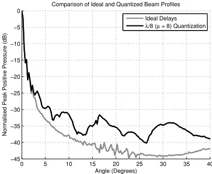
Fig. 1. Simulated radiated transmit beam profiles for phase delays with ideal accuracy and phase delays quantized toλ/8(µ= 8). Simulation parameters:
f = 5 MHz,r= 40 mm,d= 0.3048 mm.
a ’worst case’ where quantization effects were most severe. It was shown that the worst case with respect to ultrasound applications would be the use of continuous wave excitation and a combination of maximum correlated error (i.e. steered in the direction where a minimum delay increment covers two elements) and uncorrelated error (introduced as a result of focusing). Estimations for peak sidelobe levels were derived for a continuous wave case however continuous wave calcula-tions tend to over-estimate the severity of quantization lobes as described by Magninet al. [15].
The authors also commented that in the near field, transmit dynamic range is mostly limited by uncorrelated error and not correlated error (see (24) of [3]). As a consequence, this study focuses on the effect of uncorrelated error caused by non ideal focusing delay profiles.
C. Simulation
In order to demonstrate uncorrelated quantization lobes and the significance of phase quantization accuracy, ideal (non quantized) and quantized transmitted beam profiles were compared in simulation. Quantization values ofλ/8(µ= 8) [4] andλ/32 (µ= 32) [16] were chosen to reflect the suggested levels of accuracy in previous literature.
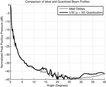
Simulations were performed with MATLAB using the Field II ultrasound simulation toolbox [17], [18]. An unsteered 96 element array of d = 0.3048 mm (equal to λ at the center frequencyf of 5 MHz) and 60% bandwidth were used with a focal distance of 40 mm. The longitudinal velocity chosen for simulation in water was c = 1500 m/s. The excitation sequence used for simulation was a 5 cycle sinusoidal tone burst with rectangular window. For the chosenf in waterλ/8 andλ/32correspond to 25 ns and 6.25 ns respectively. Results are shown in Figures 1 and 2.
[image:4.612.328.536.56.227.2]0 5 10 15 20 25 30 35 40 −45
−40 −35 −30 −25 −20 −15 −10 −5
0 Comparison of Ideal and Quantized Beam Profiles
Angle (Degrees)
N
or
m
al
is
ed
P
ea
k
P
os
iti
ve
P
re
ss
ur
e
(d
B
)
Ideal Delays
[image:5.612.66.274.57.227.2]λ/32 (µ= 32) Quantization
Fig. 2. Simulated radiated transmit beam profiles for phase delays with ideal accuracy and phase delays quantized toλ/32(µ = 32). Simulation parameters:f = 5 MHz,r= 40 mm,d= 0.3048 mm.
Fig. 2 shows theλ/32simulation with a value for TDR of 37.65 dB at 13.75◦ which is in agreement with the predicted TDR of 39.7 dB. Analysis of the ideal cases and theλ/32case show peak pressure rising due to the emergence of a grating lobe as the angle approaches 40◦. It is thought that this is not evident in the λ/8 case as it is masked by the increased sidelobe level.
The simulations show that the λ/32 threshold for phase quantization suggested by Cobbold [11] referencing [16] achieves TDR performance close to that of ideally quantized delay profiles and is therefore a much more appropriate goal for designers of phased array systems than the previously mentioned λ/8 value. It can be seen from the simulations that theλ/8value gives higher sidelobe levels when compared with theλ/32value. This is also demonstrated for any general phased array system with (7) as the RMS sidelobe level is dependent on only two variables: the number of elements, and the oversampling factor or threshold value.
Whilst this threshold value describes the relationship be-tween the excitation frequency and the transmitter minimum time increment (∆τ) it can be seen that as excitation frequency increases, the minimum time increment must decrease in accordance with λ/32. Section III describes a method to surpass the λ/32 threshold in order to improve TDR at diagnostic frequencies and achieve the λ/32 threshold for higher frequency arrays.
III. EMBEDDEDPHASELOCKEDLOOPS FORFINETIMING
CONTROL
The influence of phase quantization error on the transmitted beam profile is governed by the minimum time increment possible between adjacent transmit channels. As a conse-quence, transmitter phase quantization effects are dependent on transmitter implementation and design. The following sec-tion introduces a method using PLLs embedded within current FPGA technology to alter phases of internal clocks with close accuracy in order to improve the inter channel resolution in transmit beam forming.
A. Phase Locked Loops
A typical PLL consists of a VCO, loop filter, phase fre-quency detector, a pre-scale counter, a post-scale counter and a feedback counter as described in [19] and shown in Fig. 3. A clock of specified frequency is generated by comparing an input reference clock to an output clock. A VCO is adjusted within a negative feedback loop until the desired phase and frequency relationship between the input clock and the output clock is achieved. A number of counters can be used to multiply or divide the frequency of the output clocks accordingly using
FOU T =
M ×FIN
P×K (8)
whereFIN is the input frequency,M is the feedback counter,
P is the pre-scale counter and K is the post-scale counter. A desirable feature of PLLs and particularly of those embedded within commercial FPGA devices is their repro-grammable nature. Both Altera and Xilinx have developed PLL components which can be reconfigured during run time [20], [21]. When used within an ultrasound phased array transmitter design, fine delays which are fractions of the system clock period (at the PLL input) can be generated using a phase shifting method similar to [22] by taking advantage of current FPGA technology and using embedded PLLs with programmable phase shift.
B. Field Programmable Gate Arrays
Field Programmable Gate Arrays are commonly used as key system components within ultrasound systems; often to control excitation sequences, process data and interface to external devices ([23], [7]). FPGAs are advantageous when compared with other hardware solutions such as ASICs due to their flexible programmable nature, large amount of input/output and on-chip resources and are available at moderate to low cost. Most FPGAs include dedicated cores which are targeted to perform specific functions. Examples include on-chip soft-core processors, digital signal processing blocks and high speed transceiver buffers.
[image:5.612.317.557.629.716.2]Another example of dedicated on-chip components are Phase-Locked Loops (PLL) cores; fundamental blocks within FPGAs as they generate and distribute clock signals internally within the device. These cores operate with the same prin-ciple as the generic PLL architecture shown in Fig. 3. As FPGA technology has developed, the embedded cores within
the devices have become particularly feature rich. The main drivers for this development is the increasing requirement for high integration and scalability, reduced system complexity and component count and the emergence of high speed in-terfaces. Programmable phase shift within embedded PLLs is an example of embedded core development and permits an individual output clock’s phase to be adjusted in fine steps and in real time without interruption to PLL operation or lock [20]. Phase adjustment can be achieved using a serial interface to increment or decrement phases according to a minimum step as shown in Fig. 4 [20].
IV. HARDWAREIMPLEMENTATION
A switched excitation method for pulse compression using MOSFET devices [24] has been shown previously to be successful for single element excitation. This system avoids the use of high power linear RF amplifiers by using MOS-FETs under FPGA control to switch between discrete voltage levels. Inclusion of intermediate levels permits tapering of the excitation pulse, which is shown to reduce sidelobes in the received and filtered output.
This technology has now been scaled for multiple element excitation by using a single FPGA to drive a number of MOS-FET devices. In this configuration, the FPGA can generate MOSFET control signals, using internal arbitrary waveform generator logic. In this design arbitrary waveform generator logic creates a sampled excitation signal using a numerically controlled oscillator. Each sample value is then compared to a set of threshold levels and matched to a corresponding MOSFET level.
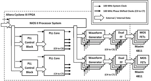
Each arbitrary waveform generator is clocked with a single global clock (100 MHz frequency in this case) and responds to a global pulse signal. Coarse phase delays of integer multiples of the global clock period (10 ns) can be implemented between channels using values stored in preloaded counters. The MOS-FET control signals from each arbitrary waveform generator are fed into a dual flip-flop (dual FF) stage. These flip flops are driven by an individual phase shifted clock per channel generated by an on-chip or embedded PLL as described in the previous section. Fine phase delays or ‘fractional delays’ (fractions of the 100 MHz system clock) are implemented using the programmable phase shift function. This introduces a phase difference between the global 100 MHz clock which generates the excitation signal and the 100 MHz channel clock used to drive the dual flip-flop output stage. The flip-flop stage is necessary in order to bridge the clock domain between the
100 MHz Output Before Dynamic Phase Shift…
100 MHz Output After Dynamic Phase Shift...
Clk_Sel Clk_Data Clk_Config Clk_Reset
Altera PLL Core In Clock
Out Clock C0 Out Clock C1 Out Clock C2 Out Clock C3 Out Clock C4 100 MHz Input
PLL Control Block
phasecounterselect
phaseupdown phasestep scanclk
Fig. 4. Example of embedded PLL phase shift control.
Waveform Generator PLL
Control Block
PLL Control
Block
PLL Core
PLL Core Delay Block
NIOS II Processor System
(C0 to C3)
C3)
(C4 to C7) (C0 to C3)
C3)
(C4 to C7)
Altera Cyclone III FPGA
100 MHz System Clock
100 MHz Phase Shifted Clocks (C0 to C7)
External / Internal Data
a.
MOS FETs Dual
FF
Dual FF
MOS FETs Waveform
Generator
Maxim 4811 Maxim
4811
Fig. 5. System diagram of an 8 channel phased array transmitter architecture using embedded PLLs and implemented within a commercial FPGA
global 100 MHz clock and the phase shifted 100 MHz clock. It is a combination of coarse delays (system clock periods) and fine delays (phase separated clocks) applied to each channel that realises a particular delay profile across an array. The MOSFET control signals from the dual flip-flop section are then fed off-chip directly into a high voltage pulser device per channel. Both the PLL control blocks and the arbitrary waveform generator blocks are controlled using a Nios II soft-core processor. The architecture described is shown in Fig. 5.
The architecture described has been implemented within a commercially available Cyclone III FPGA (Altera EP3C40Q240C8N, Altera Corporation, San Jose, CA) con-nected to eight high voltage MOSFET pulser devices (MAXIM 4811, Maxim Integrated Products inc., Sunnyvale, CA) (one per channel).
A Cyclone III contains 4 embedded PLLs each capable of distributing 5 output clocks throughout the device. Each output clock can be shifted either up or down with a minimum time increment of 96 ps with an accuracy of±50 ps. PLL output clock jitter is specified at a maximum of 300 ps for frequencies greater than or equal to 100 MHz however it must be noted that jitter is also dependent on the input clock quality. A single Cyclone III device is capable of controlling eight MAXIM 4811 pulser devices, each capable of generating five-level (0 V,±50 V,±100 V) waveforms.
[image:6.612.318.558.58.187.2] [image:6.612.58.294.640.727.2]V. EXPERIMENTALEVALUATION
A. Evaluation Across Frequency
The embedded PLL phase shift method presented in this work has a minimum time increment (∆τ) equal to 208 ps (defined by PLL settings ofFV CO = 600 MHz,M = 12,P =
1 and K = 6) which surpasses the requiredµ= 32threshold for excitation frequencies beyond 40 MHz. This section uses the UARP system to demonstrate how fixed minimum time increments (such as those generated by a 100 MHz clock) have an impact on TDR as frequency increases and how the proposed embedded PLL method can be used to improve delay resolution without increasing system clock frequency.
It is possible to demonstrate the improvement without ob-taining a number of array transducers ranging in frequencies. In this work a single array transducer of fixed frequency is used and the ∆τ is adjusted in accordance with (6). The re-lationship between excitation frequency (f) and oversampling factor (µ) is maintained whilst ∆τ is altered to reflect the increase in excitation frequency. Example transformations of ∆τ are shown in Table I.
TABLE I
EXAMPLE CONVERSIONS OF THE MINIMUM TIME INCREMENT∆τTO
SIMULATE HIGHER FREQUENCIES USING A5 MHZ ARRAY.
Excitation Value ofµat Equivalent∆τ
Frequency (f) ∆τ= 10.0 ns value for 5 MHz 5 MHz µ= 20 ∆τ= 10.0 ns 10 MHz µ= 10 ∆τ= 20.0 ns 20 MHz µ= 5 ∆τ= 40.0 ns
B. Beam Profiling
[image:7.612.76.267.349.412.2]In order to demonstrate an increase in TDR as a result of improved phase delay resolution, the radiated pressure field from a commercial diagnostic 1-D linear array transducer was measured experimentally. The transducer selected was a 128 element L3-8/40EP array transducer (Prosonic Co Ltd.,
Fig. 6. University of Leeds 96 channel Ultrasound Array Research Platform (UARP) system (front panel removed for photograph).
GyongBuk, Korea) of 5 MHz centre frequency and 3-8 MHz bandwidth. In all experiments however only the central 96 elements were excited. The excitation used for experimental evaluation was a 5 cycle tone burst of approximated sinewaves, as described in [24]. The transducer was placed within an acoustically transparent ultrasound probe cover (CIV-FLEX 610-004, Civco Medical Solutions, Kalona, IA) and sub-merged within a large tank of filtered, deionized and degassed water at a temperature of 20◦C ± 1◦C. A 0.2 mm PVDF (Polyvinylidene Fluoride) Needle Hydrophone (calibrated be-tween 1 MHz to 20 MHz with an acoustic pressure range of 50 kPa to>20 MPa RMS signal-to-noise ratio) (Precision Acoustics, Dorchester, Dorset, UK), was mounted on a 3-D computer controlled translation system able to perform lateral and radial scans of the transmitted field. Radial beam plots were obtained at r = 40mm from 0◦ to 40◦ in steps of 0.25◦. The signal from the hydrophone pre-amplifier at each radial position were digitized using an 8 bit (48 dB dynamic range) LeCroy Waverunner 64xi digital oscilloscope (LeCroy Corporation, Chestnut Ridge, NY, USA) and then processed in MATLAB. Measurements were taken five times at each point in order to produce averaged beam profiles.
VI. RESULTS
[image:7.612.328.536.518.690.2]Fig. 7 presents the transmitted beam profile of a 5 MHz array using a delay profile quantised to ∆τ = 10 ns (coarse delay resolution) and∆τ = 208 ps (fine delay resolution using the embedded PLL method). At 5 MHz ∆τ = 208 ps is equivalent to a µ value of 961 and therefore can be classed as ideal as it surpasses µ = 32. The experimental value of TDR for the embedded PLL method is approximately 32 dB goverened by a lobe at 3.75◦. It can be seen that the first significant lobe in the∆τ = 10 ns result appears at 5◦ giving a TDR value in this case of 31 dB.
Fig. 8 presents data measured using the same 5 MHz array, however in this case the ∆τ value has been adjusted
0 5 10 15 20 25 30 35 40
−45 −40 −35 −30 −25 −20 −15 −10 −5
0 Measured Beam Profiles
Angle (Degrees)
N
or
m
al
is
ed
P
ea
k
P
os
iti
ve
P
re
ss
ur
e
(d
B
)
208 ps 10 ns (5 MHz)
[image:7.612.99.263.545.717.2]0 5 10 15 20 25 30 35 40 −45
−40 −35 −30 −25 −20 −15 −10 −5
0 Measured Beam Profiles
Angle (Degrees)
N
or
m
al
is
ed
P
ea
k
P
os
iti
ve
P
re
ss
ur
e
(d
B
)
[image:8.612.328.536.56.226.2]208 ps 20 ns (10 MHz)
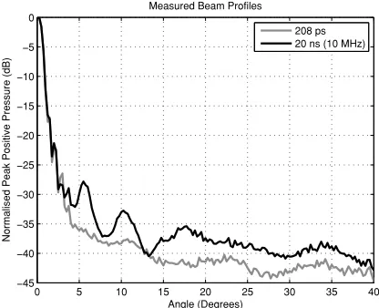
Fig. 8. Experimentally obtained averaged beam profiles (5 measurements) forr= 40 mm,d= 0.3048 mm with phase delays quantized to∆τ= 20 ns (µ= 10 atf = 5 MHz) and phase delays quantized to∆τ = 208 ps (µ= 961 at f = 5 MHz) achieved with the embedded PLL method presented in this work. The value of∆τ= 20 ns is chosen to demonstrate the effect of a quantization minimum period∆τ= 10 ns used with a higher frequency array at 10 MHz.
to predict results when the same system is used to drive a higher frequency array. In this case the coarse delay profile is quantised to ∆τ = 20 ns (coarse delay resolution). At 10 MHz∆τ = 208 ps is equivalent to aµvalue of 481 and as in the previous case, the waveform can be classed as ideal as it surpasses theµ= 32 threshold. In this measurement the value of TDR at an equivalentf of 10 MHz is 27 dB governed by a lobe at 5.5◦
Fig. 9 shows data acquired using the same 5 MHz array, however the ∆τ value has again been adjusted to predict results when the UARP system is used with a 20 MHz array with the coarse delay profile is quantised to ∆τ = 40 ns. At 20 MHz∆τ = 208 ps is equivalent to aµvalue of 240 and as per the previous cases the waveform can be classed as ideal as it still surpasses µ = 32. In this case the value of TDR at an equivalent f of 20 MHz is 22 dB governed by a lobe at 4◦
[image:8.612.66.274.57.226.2]When comparing the coarse quantized results to the ideal case obtained using the fine embedded PLL method it can be seen that at 5 MHz the gain in TDR is slight (1 dB improvement) however, as frequency increases the gain in TDR becomes significant. At higher frequencies the embedded PLL method provides an extra 5 dB gain at 10 MHz (when compared with using coarse delays at the same system fre-quency) and an extra 10 dB gain when using a 20 MHz array. This data is summarised below in Table II.
TABLE II
TDR GAIN: COARSEDELAY∆τ= 10NS VSFINEDELAY∆τ= 208PS
Excitation TDR (dB) TDR (dB) TDR Frequency (f) ∆τ= 10 ns ∆τ= 208 ps Gain (dB)
5 MHz 31 dB 32 dB 1 dB 10 MHz 27 dB 32 dB 5 dB 20 MHz 22 dB 32 dB 10 dB
0 5 10 15 20 25 30 35 40
−45 −40 −35 −30 −25 −20 −15 −10 −5
0 Measured Beam Profiles
Angle (Degrees)
N
or
m
al
is
ed
P
ea
k
P
os
iti
ve
P
re
ss
ur
e
(d
B
)
208 ps 40 ns (20 MHz)
Fig. 9. Experimentally obtained averaged beam profiles (5 measurements) forr= 40 mm,d= 0.3048 mm with phase delays quantized to∆τ = 40 ns (µ= 5 atf = 5 MHz) and phase delays quantized to∆τ = 208 ps (µ= 961 atf = 5 MHz) achieved with the embedded PLL method presented in this work. The value of∆τ= 40 ns is chosen to demonstrate the effect of a quantization minimum period∆τ= 10 ns used with a higher frequency array at 20 MHz.
The results also show an increase in the overall sidelobe level as frequency increases and the µ = 32 criteria is not met. This is consistent with the simulated predictions shown in Figs. 1 and 2.
The performance and accuracy of the embedded PLL method was verified by measuring element to element delays and calculating the deviation from the ideal theoretical delay profile. The deviation from the ideal profile to a delay profile quantized to 10 ns was also measured and calculated. Results show an RMS deviation from the ideal profile of 257.2 ps for the embedded phase shift method and an RMS deviation of 2.565 ns when coarse delays are used alone.
VII. DISCUSSION
The impact of phase quantization when minimum time increments are fixed is dependent on excitation frequency. The embedded PLL method presented and implemented in the UARP system shows greater improvement when used with higher frequency arrays such as those discussed in this work. Both simulations and experiments conducted show that achieving the λ/32 criterion reduces sidelobe levels in the transmitted beam profile to a level which mirrors the ideal case. Whilst some minor differences may exist between simu-lated data and experimental results (such as those described by Aitkenheadet. al. [25]) simulation shows comparable results with the experimental data. Comparing the experimental 5 MHz, and extrapolated 10 MHz and 20 MHz cases with the simulated versions, results show differences in sidelobe levels of approximately 2 db, 6 dB and 11 dB respectively. This indicates that the simulated result is an appropriate assessment of the gains in TDR when using the proposed method.
[image:8.612.66.282.686.748.2]pulses at high frequencies, quantization error effects are likely be present in the transmitted beam profile if ∆τ is not sufficiently small. At 20 MHz for example theλ/32threshold corresponds to a ∆τ value of 1.56 ns, whilst at 40 MHz the
λ/32 value corresponds to a ∆τ value of 781 ps. Solving this problem using external discrete circuits increases system design and complexity, particularly as channel count increases. The implementation shown in this work can achieve theλ/32 threshold for these high frequency cases and does so by merely taking advantage of resources (perhaps not intended for such an application) but readily available within FPGAs.
As an aside, the embedded PLL method presented could also be used to correct or compensate for array defects and inconsistencies in array manufacture, particularly with respect to timing variability as discussed by Zhang et. al.[26]. Other areas with which the embedded PLL method is applicable could include compensating for subtle changes in focal de-lays due to temperature, boundaries between materials, or to compensate for focal errors caused by non-ideal propagation in a medium. Using the embedded PLL method described, it would be entirely possible to incorporate additional time offsets as part of a calibration routine or to fine-tune delay parameters in order to optimise the radiation pattern.
VIII. CONCLUSIONS
Phase quantization effects such as increased sidelobe levels and phase quantization lobes can be reduced by close approx-imation to the ideal delay profile for a focused and/or steered beam in a phased array system. Most ultrasound phased array imaging suffers only from errors associated with focusing delay profiles (uncorrelated error) as opposed to periodic error caused by steering delay profiles (correlated error).
Previous literature have evaluated the effect of phase quan-tization particularly with respect to receive beamforming. Suggested values of maximum tolerable phase error have been proposed such as λ/8 value by Von Ramm et. al. and then
λ/32by Cobbold referencing [16]. These thresholds however are dependent on excitation frequency which can vary with application, imaging modality or transducer. In most cases the hardware system used is a common platform which must be able to meet the demands that these various applications and techniques impose. This work describes the implementation of a method able to surpass these suggested maximum tolerable phase error values across a range of frequencies in order to increase transmit dynamic range and when combined with receiver beamforming strategies increase total image dynamic range.
Programmable and flexible embedded PLL components are now common in commercial FPGAs. These embedded PLLs are highly functional and allow for real time phase shifting of clocks by simple serial interface. Presented in this work is a method to take advantage of these embedded PLLs to create a phased array transmitter design which can provide inter-element resolution of 208 ps using multiple phase shifted 100 MHz clocks. This phase delay solution is coupled with previous work into generation of coded excitation waveforms using MOSFET devices [24] and replicated to form part of
the University of Leeds UARP, a 96 channel ultrasound array system.
Experimental evaluation with the UARP system demon-strates that the proposed embedded PLL architecture can achieve and surpass the λ/32 criterion across a range of frequencies. Results obtained with a 5 MHz array transducer have been used to evaluate potential reductions in sidelobe levels when used at higher frequencies such as 10 MHz and 20 MHz. Results show up to 12 dB improvement at 20 MHz in peak sidelobe level, or Transmit Dynamic Range. The embedded PLL method may also be suitable for compensating or correcting for other anomalies which require fine-tuning of inter-channel delays.
ACKNOWLEDGMENTS
The authors would like to thank B. Q. Bui, T. H. Pham, O. Anwar and P. Thompson for their hard work on hardware and software development.
The authors would also like to thank Maxim Integrated Products and Texas Instruments for providing samples and GE Inspection Technologies for providing transducers.
REFERENCES
[1] B. W. Drinkwater and P. D. Wilcox, “Ultrasonic arrays for non-destructive evaluation: A review,”NDT & E International, vol. 39, no. 7, pp. 525 – 541, 2006.
[2] T. L. Szabo,Diagnostic Ultrasound Imaging: Inside Out, E. A. Press, Ed. Elsevier Academic Press, 2004.
[3] S. Holm and K. Kristoffersen, “Analysis of worst-case phase quantiza-tion sidelobes in focused beamforming,”Ultrasonics, Ferroelectrics and Frequency Control, IEEE Transactions on, vol. 39, no. 5, pp. 593 –599, Sep 1992.
[4] O. T. Von Ramm and S. W. Smith, “Beam steering with linear arrays,”
Biomedical Engineering, IEEE Transactions on, vol. BME-30, no. 8, pp. 438 –452, Aug. 1983.
[5] M. Eaton, B. Bardsley, R. Melen, and J. Meindl, “Effects of coarse phase quantization in ultrasound scanners,” in1978 Ultrasonics Symposium, 1978, pp. 784 – 788.
[6] T. Laakso, V. Valimaki, M. Karjalainen, and U. Laine, “Splitting the unit delay,”Signal Processing Magazine, IEEE, vol. 13, no. 1, pp. 30 –60, Jan 1996.
[7] J. Jensen, O. Holm, L. Jerisen, H. Bendsen, S. Nikolov, B. Tomov, P. Munk, M. Hansen, K. Salomonsen, J. Hansen, K. Gormsen, H. Ped-ersen, and K. Gammelmark, “Ultrasound research scanner for real-time synthetic aperture data acquisition,”Ultrasonics, Ferroelectrics and Frequency Control, IEEE Transactions on, vol. 52, no. 5, pp. 881 –891, May 2005.
[8] C.-H. Hu, X.-C. Xu, J. Cannata, J. Yen, and K. Shung, “Development of a real-time, frequency ultrasound digital beamformer for high-frequency linear array transducers,” Ultrasonics, Ferroelectrics and Frequency Control, IEEE Transactions on, vol. 53, no. 2, pp. 317 –323, feb. 2006.
[9] A. Lovejoy, P. Pedrick, A. Doran, T. A. Delchar, J. A. Mills, and A. Stamm, “A novel 8-bit ultrasound phased-array controller for hy-perthermia applications,”Ultrasonics, vol. 33, no. 1, pp. 69 – 73, 1995. [10] J. V. Hatfield and K. S. Chai, “A beam-forming transmit ASIC for driving ultrasonic arrays,”Sensors and Actuators A: Physical, vol. 92, no. 1-3, pp. 273 – 279, 2001.
[11] R. S. Cobbold,Foundations of Biomedical Ultrasound. Oxford Uni-versity Press, 2007.
[12] L. Azar, Y. Shi, and S. C. Wooh, “Beam focusing behavior of linear phased arrays,”NDT & E International, vol. 33, pp. 189 – 198, 2000. [13] M. I. Skolnik,Radar Handbook 2nd Edition, D. A. Gonneau and B. E.
Eckes, Eds. McGraw Hill Publishing Company, 1990.
[14] W. Beaver, “Phase error effects in phased array beam steering,” in
Ultrasonics Symposium, 1977, 1977, pp. 264 – 267.
[16] D. Peterson and G. Kino, “Real-time digital image reconstruction: A description of imaging hardware and an analysis of quantization errors,”
Sonics and Ultrasonics, IEEE Transactions on, vol. 31, no. 4, pp. 337 – 351, Jul 1984.
[17] J. Jensen and N. Svendsen, “Calculation of pressure fields from arbitrar-ily shaped, apodized, and excited ultrasound transducers,”Ultrasonics, Ferroelectrics and Frequency Control, IEEE Transactions on, vol. 39, no. 2, pp. 262 –267, Mar. 1992.
[18] J. A. Jensen, “Field: A program for simulating ultrasound systems,” in
10th Noric Baltic Conference on Biomedical Imaging, Vol. 4, Supplement 1, Part 1:351–353, 1996, pp. 351–353.
[19] Altera. (2009, Nov) Phase-Locked Loop (ALTPLL) Megafunction User Guide. pdf. Altera Corporation. 101 Innovation Drive, San Jose, CA 95135. [Online]. Available: http://www.altera.com/literature/ug/ug altpll.pdf
[20] Altera. (2009, Dec) Chapter 5, Cyclone III Device Handbook, Volume 1. pdf. Altera Corporation. 101 Innovation Drive, San Jose, CA 95135. [Online]. Available: http://www.altera.com/literature/hb/cyc3/ cyc3 ciii51006.pdf
[21] K. Kurbjan and C. Ribbing. (2010, May) XAPP879 PLL Dynamic Reconfiguration. pdf. Xilinx, Inc. 2100 Logic Drive, San Jose, CA 95124-3400. [Online]. Available: http://www.xilinx.com/support/ documentation/application notes/xapp879.pdf
[22] A. Houghton and P. Brennan, “Phased array control using phase-locked-loop phase shifters,” Microwaves, Antennas and Propagation, IEE Proceedings H, vol. 139, no. 1, pp. 31 –37, Feb. 1992.
[23] P. Tortoli, L. Bassi, E. Boni, A. Dallai, F. Guidi, and S. Ricci, “ULA-OP: An advanced open platform for ultrasound research,”Ultrasonics, Ferroelectrics and Frequency Control, IEEE Transactions on, vol. 56, no. 10, pp. 2207 –2216, Oct 2009.
[24] D. M. J. Cowell and S. Freear, “Quinary excitation method for pulse compression ultrasound measurements,”Ultrasonics, vol. 48, pp. 98– 108, 2008.
[25] A. H. Aitkenhead, J. A. Mills, and A. J. Wilson, “An analysis of the origin of differences between measured andsimulated fields produced by a 15-element ultrasound phased array,”Ultrasound in Medicine & Biology, vol. 36, no. 3, pp. 410 – 418, 2010.
[26] J. Zhang, B. W. Drinkwater, and P. D. Wilcox, “Effects of array trans-ducer inconsistencies on total focusing method imaging performance,”
NDT & E International, vol. 44, no. 4, pp. 361 – 368, 2011.
Peter SmithPeter Smith received his B.Eng. (Hons) degree in Electronic Engineering (Industrial) and a M.Sc. degree in Embedded Systems Engineering from the University of Leeds, UK, in 2008 and 2009 respectively. As part of his undergraduate studies he completed a 12 month industrial placement working within Hardware Design Verification. His postgrad-uate M.Sc. project was the design of an 8-Channel FPGA-controlled Ultrasound Transmitter design. In 2009 he joined the Ultrasound group within the School of Electronic and Electrical Engineering as a Ph.D. student. His main research interests include Ultrasound instrumentation and system design, FPGA development, and ultrasound medical imaging.
David CowellDr. David Cowell received his M.Eng. degree in Electronic and Electrical Engineering from the School of Electronic and Electrical Engineering at the University of Leeds in 2004, conducting major projects in parallel computing and embedded system design. He completed his Ph.D. degree with the Ultrasound Group in 2008, conducting research into advanced coding excitation techniques and excita-tion circuit design for industrial instrumentaexcita-tion and medical imaging systems. During this time he has performed extensive consultancy in instrumentation, FPGA and high-speed digital hardware design. After working as a research consultant in measurement and instrumentation, he joined the Ultrasound Group as a Research Fellow. His main research is currently focused on non-invasive industrial ultrasound measurement. His other active research areas include advanced miniaturized ultrasound excitation systems with low harmonic distortion for phased array imaging, ultrasound system design and signal processing.
Benjamin RaitonBenjamin Raiton is a third year PhD student who joined the Ultrasound group at the University of Leeds in December 2008. He was born in France and graduated from the University of Science Bordeaux I with an M.Eng. in Electronics Engineering and Industrial Computer Systems in 2005. Between 2005 and 2007 Ben worked on the design of Navigational Aid Equipment for airplanes for Longwater Systems Ltd, he was responsible for the design and test of the hardware within a Distance Measuring Equipment (DME). He then moved on to work for e2v Technologies where he was Lead Electronics Engineer responsible for the development and design package of Limiter Drivers for Radars. He is now doing a part-time PhD while working for Instep Solutions Ltd for whom he designs, tests and manages assembly of various sensors and logging devices. His current research is in enhancing the targeting of drugs and genes conveyed by microbubbles using ultrasound arrays.
Chau Vo KyChau Vo Ky received his B.Eng. and M.Eng degrees in Electrical and Electronics Engi-neering from University of Technology, Vietnam, in 2000 and 2003. In 2010 he received a M.Sc. in Embedded System Engineering at the University of Leeds, UK. He is now pursuing a Ph.D. de-gree in non-invasive industrial monitoring. During his career, he has worked on projects related to DSP, FPGA, microcontroller, data acquisition and monitoring, audio power amplifiers, and a project in VLSI design. His current research interests include medical electronics, microelectronic design, DSP and embedded systems.