1
PANORAMIC RADIOGRAPH AND CONE BEAM COMPUTED TOMOGRAPHY- EVALUATION OF MANDIBULAR IMPACTED THIRD
MOLAR AND MANDIBULAR CANAL
Dissertation Submitted to
THE TAMILNADU DR. M.G.R. MEDICAL UNIVERSITY
for partial fulfillment of the requirements for the degree of
MASTER OF DENTAL SURGERY
BRANCH – IX
ORAL MEDICINE AND RADIOLOGY
THE TAMILNADU DR. MGR MEDICAL UNIVERSITY CHENNAI – 600 032
2
CERTIFICATE
This is to certify that Dr.Khushboo Singh, Post graduate student (2010 – 2013)
in the Department of Oral Medicine and Radiology branch IX, Tamil Nadu Government
Dental College and Hospital, Chennai – 600 003 has done this dissertation titled
“Panoramic radiograph and Cone beam computed tomography - Evaluation of Mandibular impacted third molar and Mandibular canal” under my direct guidance and supervision for partial fulfillment of the M.D.S degree examination in April 2013 as
per the regulations laid down by Tamil Nadu Dr.M.G.R. Medical University, Chennai
-600 032 for M.D.S., Oral Medicine and Radiology (Branch – IX) degree examination.
Date: Dr. S. JAYACHANDRAN, M.D.S., Ph.D, Professor and Head of the Department,
Department of Oral Medicine and Radiology,
Tamil Nadu Government Dental College & Hospital
Chennai – 600 003.
Date: Dr.K.S.G.A. NASSER, M.D.S., PRINCIPAL,
Tamil Nadu Government Dental College & Hospital,
3
ACKNOWLEDGEMENT
I sincerely thank our Principal, Dr.K.S.G.A. Nasser, M.D.S for his support and nobleness in allowing me to conduct this study.
With supreme sincerity, obedience, deep sense of gratitude and heartfelt
appreciation, I thank my esteemed guide, DR.S.JAYACHANDRAN M.D.S., Ph.D, Professor and Head, Department of Oral Medicine and Radiology, Tamil Nadu
Government Dental College and Hospital, Chennai – 3, for his valuable guidance,
support and encouragement throughout my post graduate course and to bring this
dissertation to a successful completion.
I sincerely thank Dr.G.V.Murali Gopika Manoharan M.D.S., Professor, Dr.L.Kayal M.D.S., Reader and Dr.Capt.P.Regu M.D.S., Assistant Professor, Department of Oral Medicine and Radiology for their valuable support.
I extend my sincere thanks to Dr. N Balaji, M.D.S., who helped me in evaluation
of CBCT scans for the study, also my gratitude to the Manager and all working staff,
Aarthi scans, 60, 100 feet road, Vadapalani, Chennai – 600 026 for helping me in taking
CBCT scans.
I thank all my patients who were kind enough and cooperative to conduct my
study. I also thank my post graduate colleagues for their help and constant support.
I thank my parents for their unconditional love and affection and constant support. Without them, nothing would have been made possible. Lastly, I wholeheartedly
thank the Almighty who has showered his blessings from above and who is behind each
4 CONTENTS
S.NO. TITLE PAGE NO.
1. INTRODUCTION 1-4
2. AIMS AND OBJECTIVES 5
3. REVIEW OF LITERATURE 6-33
4. MATERIALS AND METHODS 34-38
5. RESULTS 39-59
6. DISCUSSION 60-67
7. SUMMARY AND CONCLUSION 68-69
8. BIBLIOGRAPHY 70-81
5
ABBREVIATIONS
B-L Bucco-Lingual
CT Computed Tomography
CBCT Cone Beam Computed Tomography
CBVI Cone Beam Volumetric Imaging
CMOS Complementary Metal Oxide Semiconductor
DSA Digitally Subtracted Angiography
DR Darkening of Roots
DMC Deviation of Mandibular Canal
et al And Others
FPD Flat Panel Detector
FOV Field of View
H × W Height by Width
IAN Inferior Alveolar Nerve
IAC Inferior Alveolar Canal
IWL Interruption of White line of Mandibular Canal
KV Kilovoltage
LTM Lower Third Molar
mSv Millisieverts
MA Milliampere
6
MNBR Multiprojection Narrow-beam Radiography
µSv Microsieverts
NRCP National Council on Radiation Protection and Measurements
NMC Narrowing of Mandibular Canal
OPG Orthopantamogram
PAN Panoramic Radiograph
ROI Region of Interest
S-I Supero-Inferior
SMC Superimposition of Roots on Mandibular Canal
SPSS Statistical Package for Social Sciences
ABSTRACT
Background: Management of mandibular third molar teeth requires accurate and precise
information regarding exact location and its relationship with the inferior alveolar nerve
(IAN) where these two structures are intimately related to prevent the injury of the nerve.
For pre-operative screening of the cases, intraoral and panoramic radiograph is sufficient
to determine the position of the third molar in relation to inferior alveolar nerve. But with
advent of cone beam computed tomography (CBCT), it has become easy to localize the
exact position of the tooth and IAN in all the three planes where both are closely related.
Aim: The aim of the study was to evaluate the diagnostic utility of CBCT in preoperative
assessment of impacted mandibular third molars where root tip is in direct proximity of
the IAN as evaluated in panoramic radiograph.
Materials and Methods: Study sample was composed of 20 patients (40 teeth). High risk
signs of IAN injury such as darkening of roots, interruption of white line of mandibular
canal, superimposition of roots on mandibular canal, narrowing of mandibular canal, and
deviation of mandibular canal were assessed in panoramic radiograph and subsequently
CBCT images were evaluated for exact location of mandibular canal in relation to root
tip, cortical lining of mandibular canal, and cortical plate perforation.
Results: In most of the cases mandibular canal in relation to root tip was at the level of
roots and inferiorly positioned. There was statistical significant association between
darkening of roots and cortical plate perforation, interruption of white line and absence of
corticalisation of mandibular canal and superimposition of roots on mandibular canal and
presence of corticalisation of mandibular canal.
Conclusion: In the present study, exact localization of mandibular canal was done in
relation to the mandibular third molar in all three planes with the help of CBCT in the
cases showing the high risk signs of IAN injury. CBCT proved to be a promising
diagnostic tool for preoperative assessment of mandibular third molar tooth and IAN in
complicated cases.
7
INTRODUCTION
Impaction is a pathological condition which is defined as ―lack of eruption of a tooth in
the oral cavity within the time and physiological limits of normal eruption process‖.1 A
fully developed tooth which remains in the jaw bone or under the mucosa even after its
normal eruption time is known as an impacted tooth. Most commonly encountered
impacted teeth are third molars, followed by maxillary canine and mandibular 2nd
premolar.2 Removal of the third molar is the routine surgical procedure in dentistry.
Indications for removal of an impacted mandibular third molar are orthodontic reasons3,
pericoronitis4,5, odontogenic cysts or tumors6,7,8, untreatable caries with accompanying
pain sensation or apical infection7, external root resorption of second molar.9
Management of impacted teeth requires accurate and precise diagnosis regarding location
of an impacted tooth and its relationship with the surrounding anatomical structures. It is
important to determine and evaluate the exact position of an impacted tooth, inclination
of long axis of an impacted tooth and its relationship to the neighboring structures such as
adjacent teeth, vital neurovascular structures. Neurological complications may occur
because of inappropriate diagnosis of the neighbouring anatomic structures or the
surgical approach in the cases, having close or intimate relationship between roots of
mandibular third molar and mandibular canal and or mandibular lingual cortex. The
removal of an impacted mandibular third molar can injure the inferior alveolar nerve
(IAN) and cause dysesthesia.10,11 The root tip position of an impacted mandibular third
molar is the very important and decisive factor for the nerve injury incidence. If the
position of the root tip is below the mandibular canal, the risk is approximately 3 times
8
upto 30% in cases where the root of mandibular third molar is in direct contact with the
inferior alveolar nerve.14,15,16,17 The radiographic and imaging examination is certainly an
indispensible tool for precise diagnosis and optimal management without any further
complication because it provides valuable information about tooth position, number and
morphology of roots, and relationship of tooth to adjacent anatomical structures. Always
the first choice of imaging modality should be the plain or conventional radiography
when an impacted tooth is suspected after clinical examination. For preoperative
diagnosis of routine cases, intraoral and panoramic radiographs are sufficient to
determine the position of the third molar in relation to inferior alveolar canal. But
additional information from other imaging modalities is needed in the second plane if the
tip of root is on the level or inferior to the mandibular canal to identify the position of
root tip in relation to mandibular canal.18 Moreover conventional radiographs have their
inbuilt drawbacks like superimposition, distortion of images, because of the projection of
3dimensional structures in 2 dimension hence the advanced imaging is necessary for the
assessment of impacted molars. Some studies used panoramic radiographs as a guideline
for deciding whether an axial CT (Computed tomography) was needed in addition to
preoperative panoramic radiograph for patients to undergo third molar extraction.19
CT has been used for past several years because it can provide additional and
reliable information than conventional radiographs. CT provides good tissue contrast,
eliminates blurring of image and overlapping of adjacent anatomical structures. CT
requires thin slices and a resulting high radiation dose to get precise information of the
9
Despite its advantages, until now, the use of CT for the assessment of impacted teeth has
been restricted because of issues related to cost, risk versus benefit, and access.18
CBCT (cone beam computed tomography) is a recent technology initially developed for
angiography in 1982 and subsequently applied to maxillofacial imaging.24 It uses a
divergent or ―cone‖-shaped beam of ionizing radiation and a two dimensional detector
fixed on a rotating gantry to obtain multiple sequential projection images in one complete
scan of the area of interest.24 It is only since late 1990s that it has become possible to
produce clinical systems that are both inexpensive as well as small enough to be used in
the dental office.24
Currently, many attempts through various studies have been made to investigate
the role of CBCT in the imaging of impacted teeth. CBCT imaging has the benefit of
lesser radiation exposure to the patient as compared to CT.
CBCT provides high definition three dimensional images of all oral and
maxillofacial structures at reduced cost and lesser radiation dose to the patient. It has also
overcome all the limitations of conventional imaging such as distortion of image,
magnification of image, less clarity, overlapping of anatomical structures, lack of
accuracy in measurements and not allowing for 3dimensional modeling. With the advent
of CBCT, it has become very convenient, simple and easy to determine the exact location
of impacted tooth in the jaw and its relation to the adjacent teeth as well as anatomic
structures. Many different radiographic projections were required for the localization of
an impacted tooth traditionally. Although these projections were able to identify whether
the tooth was buccal or lingual, it was still difficult to assess the proximity of impacted
10
With CBCT, the diagnosis has become a simple illustrative task, viewing the
entire dentition as well as the impacted teeth. Further additional information such as three
dimensional orientation of an impacted tooth, and direction of path of eruption is best
revealed with CBCT.
The present study was aimed to evaluate the diagnostic utility of CBCT in
assessment of relationship of mandibular canal with the impacted mandibular third
molars where these two structures are closely related to each other bearing high risk
11
AIM
The aim of the study is to evaluate the diagnostic utility of cone beam computed
tomography (CBCT) in preoperative assessment of impacted mandibular third molars
where the root tip is in direct proximity of the inferior alveolar nerve.
OBJECTIVES
The primary objective of the study is to compare the cone beam computed
tomography (CBCT) and panoramic radiograph for localization of the mandibular
canal in respective to impacted mandibular third molars.
The high risk injury signs to inferior alveolar nerve in panoramic radiographs
such as darkening of roots, interruption of white line of mandibular canal,
narrowing of mandibular canal, superimposition of roots on mandibular canal,
deviation of mandibular canal, and combination of these findings 13,17,25,26 were
evaluated and correlated with following CBCT findings:
i. Bucco-lingual position of mandibular canal
ii. Supero-inferior position of mandibular canal
iii. Presence or absence of corticalisation of mandibular canal
12
REVIEW OF LITERATURE
Definition:
―Impacted teeth can be defined as those teeth that are prevented from eruption due to a
physical barrier within the path of eruption‖ 32 (Farman, 2004).
―Peterson defined the term impaction as one that fails to erupt into the dental arch within
the expected time‖ 33 (Peterson, 1998).
―Another definition states that an impacted tooth is one which, for various reasons does
not erupt into the correct position in the dental arch at the appropriate time‖ 34,35 (Archer,
1966, Edelman and Hasharon, 1979).
―Mead has defined an impacted tooth as a tooth that is prevented from erupting into
position because of malposition, lack of space, or other impediments‖ 36 (Mead, 1954).
Four important etiologic factors which are reported in literature to explain impaction:37
1) Obstruction in the path of eruption.
2) Ectopic position of the tooth.
3) Lack of adequate guidance along the roots of the adjacent tooth.
4) General systemic diseases.
Importance of Localization of Impacted Teeth:38
The following reasons make it important to localize impacted teeth:
1. The basic principle is to not extract a well-placed tooth in proper occlusion in order to
13
time may be shortened considerably, and the result will be more definite. At the same
time, reverse also holds true. If a poorly placed tooth is kept intact and a well-aligned
tooth is extracted, then treatment time will be prolonged and the result will be less
certain.
2. An error in localization can lead to removal attempted in the wrong area.
3. The clinician must be able to assess the difficulty involved in exposing a displaced
tooth. Exposure of a malpositioned tooth may be more hazardous to the adjacent teeth
than extracting it.
The clinician may require following details about impacted teeth before intervention-
1.The precise and exact position of the crown and root apex of an impacted tooth.
2. The proximity of impacted tooth to the roots of adjacent teeth and anatomic structures.
3. The presence of any pathology and their spatial relationship with impacted tooth.
4. The orientation of anatomy of impacted tooth in 3-dimension.
Methods of Localization of impacted tooth: There are three methods of localization:
Inspection
Palpation
Radiographic and imaging modalities.
Inspection
Impacted tooth may produce bulging of the overlying mucosa on the buccal or
14
Impacted tooth may also produce drifting of adjacent teeth as an inspectory
finding.
Palpation
It is the next step in localization of impacted teeth. On palpation, an impacted
tooth can present as a bulge or swelling or prominence. Occasionally on palpation the
bony prominence may obscure an impacted tooth, and the fact that the tooth is impacted
can be missed. On palpation, if a tooth is palpable in an abnormal position or cannot be
palpated, radiographs are necessary for its localization.
Radiography-
Dental radiology has played an exciting, vital and critical diagnostic role in
dentistry, and has brought revolution in medical field with the invention of newer rapidly
expanding wide array of imaging modalities.
Intraoral radiography was first used within weeks of the discovery of X rays by
Roentgen in 1895. Extraoral imaging, including cephalometric radiography, followed
soon thereafter. Panoramic radiography has provided broad coverage of the teeth and
surrounding structures since the mid-twentieth century. Each of these modalities has
adapted to the digital revolution. Recent decades have seen the development of CT, MRI,
nuclear medicine, and ultrasonography, imaging modalities that have revolutionized
dental and medical diagnosis.
15
computerized tomography. Recently Cone beam computed tomography has been introduced for localization of impacted teeth.
Panoramic radiography- It is the basic and routine fundamental radiograph which is
simple and easy to perform and provides useful information regarding mandibular symmetry, the number of teeth present, parallelism of the roots, sequence of dental eruption, dental age, resorption of teeth, presence of pathology, variation inrelation to normal teeth as well as provides information of other structures also such as paranasal sinuses and temporomandibular joint articulation.40 Panoramic radiograph is also used to estimate the mesiodistal and vertical dimensions of impacted teeth.39 However,
localization of impacted tooth in a bucco-palatal plane is difficult, since it is a 2
dimensional radiograph. It has some advantages compared with normal computed
tomography (CT), including lesser exposure of radiation to the patient, ease of use, less
patient chair side time, better patient cooperation, lower cost, and more frequent
availability in most of the dental offices whereas drawbacks are magnification, distortion,
and overlapping of the anatomical structures.
Computerized tomography (CT) - In some past recent years, CT has become the imaging modality of choice as they provide more realistic information than conventional radiographic imaging techniques. Computerized tomography was developed by Sir Godfrey Hounsfield in 1967 and since the first prototype, there has been a gradual evolution to five generations of such systems. The method of classification for each
system is based on the organization of the individual parts of the device and the physical
16
Nonetheless, there are several limitations also with this modality. It requires the large
amount of considerable physical space and is much more expensive than other
conventional radiographic methods. The images which are captured on the detector
screens are made up of multiple axial slices, which are ‗stacked‘ to obtain a final
complete image making it time consuming. CT scan provides accurate position, orientation, and inclination of an impacted tooth, its relationship with adjacent neighbouring anatomical structures in all the three dimensions. With CT, it has become possible to localize impacted teeth accurately and precisely, relationship of impacted teeth with adjacent vital anatomic structures, presence of root resorption in the adjacent teeth and also detects the associated pathology if present. However due to high cost and especially high radiation doses39, routine use of CT for diagnosis of an impacted tooth is not justified. Currently the only indication of CT scan is where the patients show displacement of long axis of tooth due to abnormal orientation of the root apex, the presence of resorption of root or cases where exact localization of impacted teeth and its prognosis cannot be elicited by routine radiographs. It has been shown that it is superior to plain radiographs in accurately determining the crown shape, crown root relationship and orientation, and relationship to surrounding anatomic structures.41
Craniofacial CBCTs were designed to counteract some of the limitations of the
conventional CT scanning devices.42 The object to be evaluated is captured as the
radiation source falls onto a two-dimensional detector. This simple difference allows a
single rotation of the radiation source to capture an entire region of interest, as compared
to conventional CT devices where multiple slices are stacked to obtain a complete
17
less scatter radiation compared to the conventional fan-shaped CT devices, and this
considerably increases the X-ray utilization and reduces the ability of X-ray tube required
for volumetric scanning.44,45 It has been reported that the total radiation dose is
approximately 20% of conventional CTs and equivalent to a full mouth periapical
radiographic exposure.46 These component innovations are significant and allow the
CBCT to be less expensive and smaller. Furthermore, the exposure chamber (i.e. head), is
custom built and reduces the amount of radiation. The images are comparable to the
conventional CTs and also may be displayed as a full head view, as a skull view or
regional components depending upon the field of view.
Cone beam computed tomography (CBCT)-
It is a recent innovation in field of technology that has achieved the rapid
acceptance in general particularly in dentistry despite its current relatively high price
when compared with alternative imaging methodologies.
Robb RA reported the use of first CBCT scanner for angiography among at Mayo Clinic in 1982.47 Later, several other systems were developed specifically for
angiography. Fahrig et al. developed a CBCT system based on an image intensifier and
C-arm for use in angiography.48 Saint-Felix et al developed a CTA CBCT system based
on the gantry of a conventional CT scanner which reconstructs vasculature from a set of
digitally subtracted angiography (DSA) images.49
CBCT systems are also used for radiation therapy planning, in mammography,
and interoperatively for otorhinolaryngological surgery. Jaffray and Siewerdsen developed a CBCT system for radiotherapy guidance based on an amorphous silicon
18
In late 1990s only that it has become possible to create clinical systems that are
both inexpensive and small enough to be used in the dental office. The first commercial
CBCT system for oral and maxillofacial imaging was the NewTom (Quantitative Radiology, Verona, Italy), which was first approved by the Food and Drug
Administration (FDA) in April 2001, and is currently in its fourth generation as the NewTom VG. Since that time numerous additional systems have been approved or are in
development.43
Presently, the available CBCT equipments differ in size, possible settings, area of
image capture (field of view), and clinical usage.
CBCT has application in several diagnostic areas, such as implant treatment, oral
surgery, endodontic treatment, and tempomandibular joint imaging. The great advantage
of this technology is that offers 3-dimensional (3D) imaging of dental structures and
provides clear images of highly contrasted structures, such as bone. In comparison to the
conventional computed tomography, CBCT technology in clinical practice has significant
advantages such as minimization of the dose of radiation to the patient, accuracy of
image, rapid scanning time, lesser image artifacts, chair-side image display, high spatial
resolution and real-time analysis.40, 51, 52
It uses a divergent or ―cone‖-shaped52
source of ionizing radiation and a two
dimensional area detector fixed on a rotating gantry to acquire multiple sequential
projection images in one complete scan around the area of interest. Four technological
factors have contributed to make this possible: 1) the development of compact high
quality flat panel detector arrays, 2) reduction in the cost of computers capable of image
19
exposure and, 4) limited volume scanning (e.g., head and neck), eliminating the
requirement of sub second gantry rotation speeds.24
This technology has been given several names including-
Dental Volumetric Tomography
Digital Volumetric Tomography
Cone Beam Volumetric Tomography
Cone Beam Computed Tomography
Dental Computed Tomography
Cone Beam Imaging
Principles of cone beam computed tomography-
All CT scanners consist of an x-ray source and detector mounted on a rotating gantry.
During rotation of the gantry, the receptor detects x rays attenuated by the patient. These
recordings constitute ―raw data‖ that is reconstructed by a computer algorithm to generate
cross sectional images whose component picture element (pixel) values correspond to
linear attenuation coefficients. CT can be divided into 2 categories on the basis of
acquisition x ray beam geometry, namely fan beam and cone beam.24 Cone beam
scanners use a 2 dimensional digital array providing an area detector unlike linear
detector as CT does. This is combined with a three dimensional (3D) x-ray beam with
circular collimation so that the resultant beam is in the shape of a cone, hence the name
―cone beam.‖ Because the exposure incorporates the entire region of interest (ROI), only
one rotational scan of the gantry is necessary to acquire enough data for reconstruction.
Cone beam geometry has inherent quickness in volumetric data acquisition and therefore
20
volumetric dataset from which the voxels are extracted. Voxel dimensions are dependent
on the pixel size on the area detector. Therefore CBCT units in general provide voxel
[image:21.612.79.568.183.494.2]resolutions that are isotropic- equal in all three dimensions.24
Fig 1: A. Fan shaped x-ray beam with linear detector in Conventional CT B. Cone shaped beam of x-rays with flat panel detector in CBCT
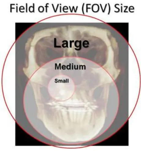
Field of View-
Scanners using flat panel detectors (FPD) describe the dimensions of their cylindrical
field of view‘s (FOV) as height by width (HxW). Width also can be referred to as
diameter. Field of view refers to the area of the anatomy that is captured by the scan.
21 1. Large field of view-
A scanner with large field of view will show the roof of the orbits and nasion down to the
hyoid bone. Scanners with large FOV, usually a FOV height equal to or greater than 16
cm, are useful for cephalometrics and traditional orthodontic surveys.
Eg- Next Generation (Platinum) i-CAT developed by Imaging Sciences International has
a FOV of 17x23 cm.
Kodak 9500 developed by Carestream has a FOV of 18x21cm.
New Tom 3G developed by Imaging Sciences has a FOV of 20x20x20 cm
2. Medium field of view-
Medium FOV scanners will capture the middle of the orbits down to menton vertically,
and condyle to condyle horizontally. Scanners with a medium FOV are useful for
panoramic radiograph and implant surveys, but not for cephalometric analysis.
Eg- New Tom 9000 by Aperio services has a FOV of 15x15x15cm
I-CAT services by Imaging Sciences International have a FOV of 8x14 cm.
3. Small field of view-
Scanners with a small FOV capture a user-defined region, usually symmetrical in shape.
Small FOV scanners are used for implant surveys, TMJ surveys, and the localization of
22
Eg- Kodak 9000 3D and Kodak 9000 3DC developed by Carestream has a FOV of
4x5cm
ProMax 3D manufactured by Planmeca has a FOV of 8x8cm.
[image:23.612.78.539.177.670.2]
23
The use of CBCT technology in clinical practice provides the number of potential
advantages for maxillofacial imaging compared with conventional CT24:
X-ray beam limitation: Reducing the size of the irradiated area by collimation of
the primary x-ray beam to the area of interest minimizes the radiation dose. Most
CBCT units can be adjusted to scan small regions for specific diagnostic tasks.
Others are capable of scanning the entire craniofacial complex when necessary.
Image accuracy: The volumetric data set comprises a 3D block of smaller cuboid
structures, known as voxels, each representing a specific degree of x-ray
absorption. The size of these voxels determines the resolution of the image. In
conventional CT, the voxels are anisotropic — rectangular cubes where the
longest dimension of the voxel is the axial slice thickness and is determined by
slice pitch, a function of gantry motion. Although CT voxel surfaces can be as
small as 0.625 mm square, their depth is usually in the order of 1–2 mm. All
CBCT units provide voxel resolutions that are isotropic — equal in all 3
dimensions. This produces sub-millimetre resolution (often exceeding the highest
grade multi-slice CT) ranging from 0.4 mm to as low as 0.125 mm (Accuitomo).
Rapid scan time: Because CBCT acquires all basis images in a single rotation,
scan time is rapid (10–70 seconds) and comparable with that of medical spiral CT
systems. Although faster scanning time usually means fewer basis images from
which to reconstruct the volumetric data set, motion artifacts due to subject
movement are reduced.
Dose reduction: Published reports indicate that the effective dose of radiation
24
98% compared with ―conventional‖ fan-beam CT systems (average range for
mandible 1,320–3,324 μSv; average range for maxilla 1,031–1,420 μSv). This
reduces the effective patient dose to approximately that of a film-based periapical
survey of the dentition (13–100 μSv) or 4–15 times that of a single panoramic
radiograph (2.9–11 μSv).
Display modes unique to maxillofacial imaging: Access and interaction with
medical CT data are not possible as workstations are required. Although such data
can be ―converted‖ and imported into proprietary programs for use on personal
computers (e.g., Sim/Plant, Materialise, Leuven, Belgium), this process is
expensive and requires an intermediary stage that can extend the diagnostic phase.
Reconstruction of CBCT data is performed natively by a personal computer. In
addition, software can be made available to the user, not just the radiologist, either
via direct purchase or innovative ―per use‖ licence from various vendors (e.g.,
Imaging Sciences International). This provides the clinician with the opportunity
to use chair-side image display, real-time analysis and MPR modes that are task
specific. Because the CBCT volumetric data set is isotropic, the entire volume can
be reoriented so that the patient‘s anatomic features are realigned. In addition,
cursor-driven measurement algorithms allow the clinician to do real-time
dimensional assessment.
Reduced image artifact: With manufacturer‘s artifact suppression algorithms and
increasing number of projections, our clinical experience has shown that CBCT
images can result in a low level of metal artifact, particularly in secondary
25 Specific applications CBCT in dentistry: 24
CBCT technology has a substantial impact on the maxillofacial imaging. It has been
applied to diagnosis in almost all the areas of dentistry and now its role is also
expanding into treatment fields.
Implant site assessment-
CBCT has been playing a very important role in planning of dental implant
placements. It provides cross sectional images of the alveolar bone height, width
and angulation and accurately shows the vital structures in the maxilla and
mandible accurately and precisely. A diagnostic stent is made with radiographic
markers and inserted at the time of scan. This also gives an exact reference of the
location of the proposed implants.
Orthodontics and Three Dimensional Cephalometry-
CBCT provides clear-cut position of impacted and supernumerary teeth and their
relationship to the adjacent teeth and neighbouring anatomical structures. Also
added information regarding dimensions and morphological features, tooth
inclination and torque, resorption of root and available alveolar bone width for
bucco-lingual movement of teeth can be gained.
Temporomandibular joint-
CBCT provides multiplanar and 3 dimensional images of the condyle and
surrounding structures to facilitate analysis and diagnosis of bone morphologic
26
developmental anomalies of the condyle, ankylosis, and rheumatoid arthritis
disease etc.
Conditions of the maxillofacial complex-
CBCT can assist in assessment of many conditions of the jaws such as
supernumerary teeth, fractures or split teeth, periodontal and periapical diseases.
Benign calcifications (e.g., tonsilloliths, lymph nodes, salivary gland stones) can
also be identified by location and differentiated from potentially significant
complications of the arteries such as carotid artery calcifications or veins (e.g.,
phleboliths). CBCT has been valuable for trauma and for assessing the extent and
degree of involvement of osteomyelitis.
Albert DG et al conducted a study in 2006 and did comparative analysis between
27
Neugebauer J et al conducted a study in 2008 and said that the removal of mandibular third molars needed information about the relative position of the tip of the root and the
inferior alveolar nerve. Comparison was done using panoramic radiograph (PAN) and PA
cephalometric radiograph (PA) under conventional radiologic techniques and cone beam
volumetric imaging (CBVI) and the diagnostic value was evaluated. Evaluation was done
by six observers of 30 PAN and PA and 30 CBVI for the position of the tip of the root
and rating was performed from 1 to 5 (excellent to poor) of the diagnostic information. It
was observed that in the vertical dimension median rating received the score of 2 (good)
for CBVI and for PAN&PA; for the horizontal dimension, CBVI got the median rating of
2 (good), PAN and PA got significantly worse median rating of 3 (sufficient). The
variability was high for the horizontal dimension with PAN and PA. Conclusion was
that the CBVI improved the localization of mandibular third molar for surgical planning
of removal of third molars.54
Nakagawa Y et al conducted a study in 2002 and evaluated the preoperative diagnostic utility of Dental three-dimensional (3D)-CT before minor oral surgical procedures. The
42.7 mm-high and 30 mm-wide rectangular solid images was provided by Dental 3D-CT.
Clear demonstration of lesions in the maxillary and mandibular bone was shown by
Dental 3D-CT. Resorption of the bone was revealed more clearly in the Dental 3D-CT
compared to Conventional radiographs. Information about location of the lesion and the
relationship between the lesion and neighbouring anatomical structures like mandibular
canal and maxillary antrum, was very useful for execution of minor oral surgical
28
before surgical procedures due to its added advantages of high resolution and low
radiation dose.55
Ghaeminia H et al conducted a study in 2011 and assessed the utility of cone beam computed tomography (CBCT) in the planning of treatment of mandibular impacted third
molars having high risk of injury to inferior alveolar nerve (IAN). Patients with the high
risk of IAN injury, as assessed on panoramic radiographs, were included in the study and
further additional CBCT imaging was taken for all the patients. Planning of the surgical
procedure was done by two oral surgeons and the risk assessment of IAN injury in
panoramic radiographs and in CBCT images was performed. The sample consisted of 40
patients having mean age 27.6 years with 53 impacted mandibular third molars.
Statistical analysis showed significant result (P<0.005) of risk assessment for IAN injury
on the basis of panoramic radiographs compared with CBCT images. After assessing the
CBCT images, more patients were reclassified to a lower risk for IAN injury after the
panoramic radiographic evaluation. This change in risk assessment also resulted in the
modification of the surgical technique with statistical significance (P<0.03). This study
concluded that CBCT contributes to better risk assessment and hence, more optimal
surgical planning as compared with panoramic radiography.56
Nakayama K et al did a study in 2009 to evaluate the ability of dental 3-dimensional computed tomography to analyze and predict the exposure and injury to the inferior
alveolar nerve (IAN) after mandibular third molar removal. Removal of 1,853
mandibular third molars in 1,539 patients was performed. Dental 3D-CT was done for 53
third molars in 47 patients among them. In 35 cases (66%), mandibular third molars were
29
dental 3D-CT intraoperative IAN exposure was seen in 17 (49%) contact cases whereas
in 2 (11%) noncontact cases on dental 3D-CT images. Removal of mandibular third
molars done in 53 cases in whom dental 3D-CT examinations was done, IAN injury was
seen in 8 cases (15%). IAN injury following IAN exposure was seen in 36.8% of the
cases whereas IAN injury without IAN exposure was seen only in 2.9% of the cases. IAN
injury incidence was 23% in the third molar-mandibular canal contact cases was 23% and
all the 8 cases with IAN injury (100%) were third molar-mandibular canal contact type. It
was concluded that contact of IAN and mandibular third molar root apices in dental
3D-CT predicts an increased risk for IAN exposure or injury.57
Susarla SM et al conducted a study in 2007 to evaluate the role of preoperative computed tomography (CT) imaging of the inferior alveolar nerve (IAN) preoperatively
for the cases having high risk for IAN injury while mandibular third molar (M3) removal.
Sample was consisted of patients who reported for M3 extraction and had been predicted
as an increased risk for inferior alveolar nerve injury in panoramic radiograph. CT
imaging was done preoperatively for all patients to assess the position of IAN in relation
to M3.The predictor variable was preoperative risk assessment of IAN injury in
panoramic radiograph and outcome variable was preoperative risk assessment of IAN
injury in CT imaging. The number of IAN injuries was documented. Descriptive statistics
were computed. The sample was composed of 23 patients having bilaterally impacted M3
age group ranging from 18-48 years. After assessing the panoramic radiographic, 80.4%
of M3s were classified as high risk for IAN injury. After assessment of the CT images,
32.6% were classified as high risk for IAN injury. After analysis of all imaging findings,
30
the cases. 3 patients reported with dysesthesia (9.1%) 1 week postoperatively moreover
none had the permanent nerve injury. So it was that additional valuable information
provided by CT imaging led to the modification of applied surgical approach and hence
converted high risk IAN injury to low risk IAN injury.58
Flygare L et al conducted a study in 2008 to critically review the role of radiographic imaging prior to mandibular third molar extraction and to propose a strategy for
preoperative imaging on basis of available scientific evidences as well as clinical
experience. From the Medline database, original articles and reviews which encompassed
the MESH terms "third molar" and "radiography" were chosen. It was found that the
scientific literature and evidences on the preoperative imaging methods of mandibular
third molar teeth were low. Therefore, information collected from the literature resources
was combined with the author‘s clinical experience. It is suggested that intraoral and
panoramic radiograph are sufficient as preoperative imaging in the cases where there is
no overlap or close relationship between the mandibular canal and the mandibular third
molar and in addition, posteroanterior open mouth projection will be sufficient for the
remaining cases whereas in cases showing intimate or close relationship between the
mandibular canal and the mandibular third molar, indication of cone beam computed
tomography or low-dose computed tomography is present.59
Tantanapornkul W et al conducted a study in 2007 to analyze and assess the diagnostic accuracy of cone-beam CT compared with panoramic images in prediction of
neurovascular bundle exposure during removal of impacted mandibular third molars. 142
impacted mandibular third molars were evaluated on panoramic radiograph and cone
31
findings were correlated with intraoperative findings. The calculation of sensitivity and
specificity of both the imaging techniques was done for the prediction of neurovascular
bundle exposure. The sensitivity and specificity of cone beam CT were 93% and 77%
and 70% and 63% for panoramic images, respectively. So, it was concluded that cone
beam CT was significantly superior in assessing and predicting neurovascular bundle
exposure to panoramic radiograph prior to the extraction of impacted mandibular third
molar.60
Suomalainen A et al conducted a study in 2010 with the aim to compare the reliability of cone-beam computerized tomography (CBCT) and other radiographic techniques to
determine number of roots of mandibular third molar and their relationship to inferior
alveolar canal (IAC) preoperatively. Forty-two teeth were enrolled in the study and were
imaged using CBCT and other imaging modalities which were panoramic imaging,
multiprojection narrow-beam radiography (MNBR), and cross-sectional tomography.
Diagnosis of two oral radiologists and radiologic diagnosis at operation were compared
using kappa values as statistical analysis. Cone-beam CT was more reliable than
panoramic radiograph in showing number of roots of mandibular third molar. CBCT
images were highly reliable in localization of IAC, whereas MNBR was not reliable and
cross-sectional tomography showed results between the two. IAC could not be interpreted
in one-third of the cases using cross sectional tomography. So, it was concluded the
CBCT was preferred and recommended for preoperative radiographic evaluation of
complicated cases.61
32
mandibular third molars was done using panoramic radiography. The teeth were
categorized into erupted and unerupted and were further subdivided depending upon the
tooth angulation. The measurement of distance from the most inferior aspect of
mandibular third molar to the superior border of IAC was done using digital caliper
device. A ―t‖ test was done to compare erupted and unerupted teeth, and ANOVA was
done to detect difference based upon tooth angulation. A review based on records was
done to evaluate the inferior alveolar nerve paresthesia incidence on the basis of
measured distances. The mean distance was 0.88mm from erupted mandibular third
molar to the inferior alveolar canal and was significantly different from unerupted teeth
(P=.002). The most inferior portion of the teeth was below the superior border of IAC for
unerupted teeth suggested by the mean values as follows: vertical (-0.61mm),
mesioangular (-0.97mm), distoangular (-0.31mm) and horizontal (-0.24). It was also
found that mesioangular impaction (-0.66mm) was most commonly associated with
inferior alveolar nerve paresthesia. It was concluded from the study that mesioangular
mandibular third molar impactions were most closely related and positioned to the
inferior alveolar canal, and it may represent an independent risk factor for postoperative
paresthesia.62
Szalma J et al conducted a case-control study in 2010 to assess the accuracy of panoramic radiographic signs in prediction of inferior alveolar nerve (IAN) paresthesia
after mandibular third molar removal. The sample was consisted of 41 cases with
postoperative IAN paresthesia and 359 control cases with no postoperative IAN
paresthesia. The gathered data included "classic" specific signs indicating the intimate
33
curvature of roots, and also the extent of IAC-root tip overlapping. It was found that 3
specific signs were significantly associated with IAN paresthesia (P < .001) and they
were interruption of the superior cortex of the canal wall, darkening of root, and diversion
of the canal. The range of sensitivities and specificities varied from 14.6% to 68.3% and
from 85.5% to 96.9%, respectively. This study concluded that for screening, panoramic
radiograph was not sufficient for prediction of IAN injury and postoperative paresthesia
after mandibular third molar extraction.63
Blaeser BF et al conducted a case-control study in 2003 to assess the association between specific panoramic radiographic signs and inferior alveolar nerve (IAN) injury
during mandibular third molar extraction. Subjects who all underwent extraction of
mandibular third molar were only included in the study. Sample was composed of 8 cases
and 17 controls. Patients with confirmed IAN injury after third molar removal were
designated as cases, whereas patients without IAN injury after third molar extraction
were designated as controls. Preoperative panoramic radiographs for the presence of high
risk radiographic signs were assessed by five surgeons who were blinded to the injury
status. The sensitivity, specificity, and positive and negative predictive values were
calculated for each radiographic sign. Statistical significant association was shown
between positive radiographic signs and IAN injury with P value <0.0001. This study
confirmed the previous studies analyses stating that panoramic findings of diversion of
the inferior alveolar canal, interruption of the cortical white line, and darkening of the
third molar root were statistically associated with IAN injury. This study also
34
positive radiographic findings, whereas presence of one of these positive radiographic
finding was associated with an increased risk of nerve injury.64
Sedaghatfar M et al conducted a study in 2005 to evaluate the sensitivity and specificity of panoramic radiographic findings in respect to inferior alveolar nerve (IAN) exposure
after mandibular third molar (M3) removal. The study design was retrospective cohort
model. The presence or absence of greater or equal to one panoramic radiographic signs
associated with an increased risk of IAN injury was used as the primary predictor value
whereas surgeon‘s assessment of IAN exposure risk was used as the secondary predictor
values. IAN exposure which means the direct visualization of IAN during mandibular
third molar extraction was used as outcome variable. The sample was consisted of 423
mandibular M3s evaluated and extracted. IAN exposure was seen in 24 (5.7%) extraction
sites following the mandibular M3 removal. It was also found that the four radiographic
signs (darkening of root, interruption of white line, diversion of the canal, and narrowing
of the root) were statistically associated with IAN exposure following mandibular M3
removal ( P < or = .05). The clinicians preoperative prediction of the likelihood of
exposure of IAN was statistically associated with exposure of IAN after M3 removal with
P value < .001, sensitivity = 0.79, specificity = 0.86). It was also found that risk of IAN
exposure intraoperatively was statistically associated with the estimated IAN exposure
risk on panoramic radiograph.65
Susarla SM et al conducted a study in 2010 to assess the association between inferior alveolar nerve (IAN) canal cortical integrity and IAN exposure intraoperatively in
computed tomography (CT). The study was a retrospective cohort model. The patients
35
study. The sample consisted of 51 subjects having 80 third molars.IAN canal integrity
indicated as intact or interrupted evaluated on coronal CT images was used as primary
predictor variable and length of cortical defect in millimeters was used as secondary
predictor variable. Intraoperative visualization of IAN was used as primary outcome
variable.52 third molars (64.1%) out of 80 third molars showed the evidence of loss of
cortical integrity of IAC. 2.9 +/- 2.6 mm was the mean cortical defect length. The length
of cortical defect > or = 3 mm was shown to be associated with high risk of IAN
visualization intraoperatively with the both high sensitivity as well as specificity (> or =
0.82). It was concluded that for the prediction of IAN exposure intraoperatively, cortical
defect size evaluated on CT images showed high sensitivity and specificity.66
Jerjes W et al conducted a retrospective study in 2006 to assess the relationship between preoperative panoramic findings and postoperative inferior alveolar nerve paresthesia
after mandibular third molar removal, and also to evaluate the surgical difficulty. Two
groups of patients were randomly selected. Patients presented with IAN paresthesia after
mandibular third molar removal were included in first group and patients presented with
no complication of IAN paresthesia were include in second group. Radiological findings
were gathered from the panoramic radiographs of these patients and were compared to
postoperative paresthesia. The degree of surgical difficulty was also evaluated
radiographically. Parameters like type of impaction (fully impacted), ramus/space (class
3), depth of impaction (depth C), spatial relationship (distoangular and horizontal), shape
of root (thick and incomplete), number of roots (multiple and incomplete), shape of the
tip of root (curved and incomplete), and relation to IAN (touching, superimposed, or
36
It was also stated that where lower third molar is > or = 1 mm from IAC, 98% there is no
probability of numbness but in cases where tooth is in contact with IAC, probability of
paresthesia is 60%. Statistics also showed that interruption of white line of IAC has 54%
probability of paresthesia, narrowing of root has 87% probability of paresthesia,
diversion of canal has 60% probability of paresthesia, and darkening of root has 42%
probability of paresthesia. So it was concluded that factors depth of impaction, ramus
relationship/space available, spatial relationship, number and shape of roots, and relation
of the root to the IAN can help in assessing surgical difficulty of mandibular third molars
radiographically.67
Park W et al conducted a retrospective study in 2010 to assess the relationship between paresthesia following mandibular third molar (MTM) removal and the cortical integrity
of the inferior alveolar canal (IAC) by means of computed tomography (CT). Subjects
were selected on the basis of panoramic radiographic finding of high risk of injury to
inferior alveolar nerve. All these subjects subsequently underwent CT imaging also and
extraction of MTM. Contact relationship between the IAC and the MTM as assessed on
the CT image was used as primary predictor variable and were further categorized into
three groups: group 1showing no contact; group 2 showing contact between the MTM
and the intact IAC cortical lining; group 3 showing contact between the MTM and the
interrupted IAC cortical lining. The number of CT image sections showing the cortical
interruption of IAC was taken as secondary predictor variable. The outcome variable
assessed was the absence or presence of postoperative paresthesia following MTM
removal. The sample consisted of 179 subjects who underwent 259 MTM removals. The
37
maximum prevalence of paresthesia was shown by group 3 which was 11.8 percent,
while for group 2 showed 1% and group 1 showed 0%. Statistical significant results were
found between frequency of inferior alveolar nerve damage and the number of CT
sections showing loss of cortical integrity of IAC (P value=0.043). So it was concluded
that the loss cortical integrity of IAC was associated with an increased risk of paresthesia
following MTM surgery.68
Palma-Carrió C et al conducted a study in 2010 with the aim of literature review of preoperative radiographic signs in orthopantomogram (OPG) and computed tomography
(CT) associated with the risk of inferior alveolar nerve injury during the surgical removal
of lower third molar (LTM). PubMed search was done for the literature evidences
published between the years 2000 and 2009. Among the reviewed literatures,
radiographic signs in the OPG which indicates a close relationship between the LTM and
the inferior alveolar canal were taken into consideration as the risk factors for the inferior
alveolar nerve damage. These signs were darkening and deflection of the root, and
interruption and diversion of the white line of the mandibular canal. The regular routine
use of CT is not justified in all the cases, and is only indicated in the cases where
radiographic signs in the OPG demonstrate a close anatomical relationship between the
LTM and the mandibular canal. CT showing the absence of cortical lining of the
mandibular canal denotes the contact between the root of the LTM and the mandibular
canal, and is also related with the presence of some specific radiographic signs in the
OPG.69
38
intimate relationship between the root and mandibular canal. 253 impacted mandibular
third molars were assessed in the study. Imaging evaluation was done of both digital
panoramic radiography and cone beam CT. Panoramic images were assessed to
determine the presence or absence of darkening of the apical part of root of mandibular
third molar. Cone beam CT images were evaluated for the following two findings: (1)
grooving of the root and (2) thinning or perforation of the cortical plate by the root.
Panoramic finding of darkening of the root was shown by 80 impacted mandibular third
molars out of 253 impacted mandibular third molars. Cone beam CT finding of cortical
thinning or perforation was significantly correlated with the darkening of root as
panoramic finding (80%, P, 0.001). So conclusion was given that panoramic finding of
darkening of roots depicts cortical plate thinning or perforation in cone beam CT.70
F Sampaio Neves et al conducted a study in 2012 to evaluate the reliability of four panoramic radiographic findings (darkening of roots, narrowing of mandibular canal,
diversion of mandibular canal, and interruption of white line) in prediction of the absence
of corticalization between the mandibular canal and the mandibular third molar on cone
beam (CB) CT images. The sample was composed of 142 mandibular third molars who
underwent preoperative radiographic assessment prior to removal of impacted
mandibular third molars. It was found that darkening of root and interruption of white
line of mandibular canal on panoramic radiograph was significantly associated with
absence of corticalisation of mandibular canal in CBCT images (P value <0.05)No
statistically significant association was observed for the other panoramic radiographic
findings, either individually or in association (P>0.05). This study concluded that
39
requires further 3 dimensional evaluation of relationship between mandibular canal and
impacted mandibular third molar to predict the risk of IAN injury during mandibular
40
MATERIALS AND METHODS
The study was conducted at
Department of Oral Medicine and Radiology,
Tamil Nadu Government Dental College and Hospital,
Chennai – 600 003.
Aarthi scans,
60, 100 feet road, Vadapalani,
Chennai – 600 026.
The study protocol was approved by the Institutional Ethical Committee.
Duration of the study: From May 2012 to November 2012 (7 months) Sample design:
Totally 20 patients were included under the study. The cases reported with
impacted lower third molars for routine investigation and treatment were selected from
the Department of Oral Medicine and Radiology, Tamil Nadu Government Dental
College and Hospital, Chennai – 600 003 between May and November 2012. All were in
the age group of 22 – 30 years (mean age = 26 years) of either gender. A total of 40
impacted teeth were assessed in this study.
Design of the study: A prospective study
41 Inclusion criteria:
Patients having age group ranging from 22 to 30 years (mean age = 26 years) of
either gender.
Presence of one or both impacted mandibular third molar.
Patients who are willing and able to attend throughout radiographic assessment.
Exclusion criteria:
Uncooperative patients
Patients reporting with maxillofacial trauma
Patients suffering from severe physical and/ or mental disability
Pregnant patients
Unwilling to participate in the study
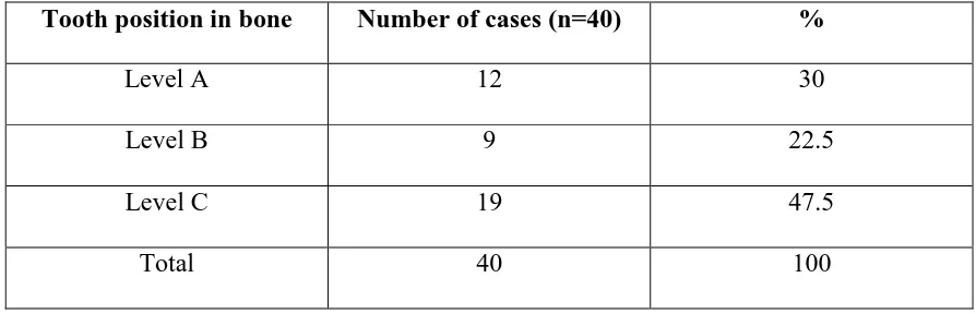
Clinical and radiological criteria for diagnosis of impacted teeth:
Partially/Completely unerupted permanent teeth even after normal eruptive age.
Radiographic evidence of partially/completely unerupted fully developed teeth.
Armamentarium: Disposable gloves
Face mask
Patient‘s apron
Stainless steel tray
Mouth mirror
Tweezer
42 Gauze
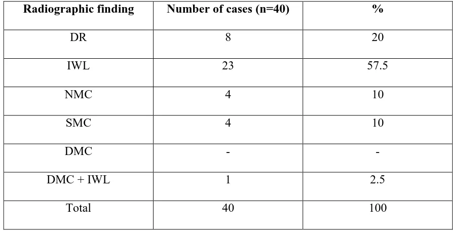
Thorough clinical examination was done in all the patients. There are several
radiographic signs in panoramic radiograph which are considered as risk factors for
injury to inferior alveolar nerve such as darkening of roots, interruption of white line of
mandibular canal, narrowing of mandibular canal, superimposition of roots on
mandibular canal, deviation of mandibular canal, and combination of these
findings.13,17,25,26 Patients having one of these radiographic signs as diagnosed in
panoramic radiograph were only included in the study. Further, all these patients were
subjected to the additional CBCT evaluation. The panoramic findings were also evaluated
and confirmed in CBCT reformatted panoramic images. Cross sectional CBCT images
were evaluated for bucco-lingual position of mandibular canal, supero-inferior position of
mandibular canal, absence or presence of corticalisation of mandibular canal, and cortical
plate perforation.
Panoramic radiograph:
Kodak 8000C digital panoramic and cephalometric system was used to obtain
panoramic radiograph. Scanning parameters were 12mA, 73kV and 13.9 seconds
scanning time. Before the exposure, patients were advised to remove dental appliances,
earrings, necklaces, hairpins or any other metallic objects in the head and neck region if
any. The correct antero-posterior positioning was achieved by making the patient to keep
the maxillary and mandibular incisors into the notch of the bite block. The patient head
was then positioned properly in all the three orthogonal planes and exposure was made.
43 Cone beam computed tomography (CBCT):
KODAK 9500 cone beam 3D Extraoral imaging system with a reconstruction
volume of 50x37mm and a reconstructed matrix voxel of 76.5x76.5x76.5µm was used to
obtain the CBCT images. The equipment has CMOS sensor technology. Exposure
parameters for the patients varied from 90 kV, 10 mA with a scan time of 10.8 seconds.
Patients were positioned in standing position while taking the scan. The total image acquisition time was less than 2 minutes. The impacted teeth were assessed by the 3 D
volumetric image and 1 mm tomographic sections in sagittal, axial and coronal planes.
The field of view was 9 x 15cm (from the bottom of the chin to the top of the jaw).
Tomographic sections were taken in curved planar reformation (panorex), a series of
multiplanar reconstructions (cross sections).
Curved planar reformation: This is a type of multiplanar reformation accomplished by aligning the long axis of the imaging plane with a specific anatomic structure (arch
form).24 This mode was useful in displaying the dental arch, providing familiar
panoramic like thin-slice images, which were useful to study inferior alveolar canal in
contact with impacted third molar.
Basic enhancements included zoom or magnification and visual adjustments to
narrow the range of displayed grey-scales (window) contrast level within the window to
annotations and cursor-driven measurements.24
Radiation exposure:
Single Panoramic radiograph – 2.9 to 11 µSv.27,28
44
The radiographic exposure for patients was well below the maximum permissible
dose of 2.4 mSv as per the NCRP guidelines.31
Radiation safety precautions such as filtration, collimation, and patient protection
equipments like thyroid collar, lead apron, and gonadal shield were used before
45
[image:46.612.145.520.62.727.2]PHOTOGRAPHS ARMAMENTARIUM DIAGNOSTIC INSTRUMENTS
FIGURE 1
PANOREX MACHINE FIGURE 2
46
[image:47.612.245.408.149.371.2]PATIENT POSITIONING IN PANOREX MACHINE FIGURE 4
[image:47.612.243.410.490.722.2]47
CLINICAL CASES
INTERRUPTION OF WHITE LINE
Photograph showing partially erupted 48
48 Cropped CBCT reformatted panoramic image
showing mesioangularly impacted 48 at level C, interruption of white line
Cropped CBCT reformatted panoramic image showing marked outline of
mandibular canal
Coronal section of CBCT showing mandibular canal in vertical plane present inferior to the roots, in horizontal plane present at tle level of roots, absence of
corticalisation of mandibular canal, and lingual cortical plate perforation Mandibular canal
49
SUPERIMPOSITION OF ROOTS ON MANDIBULAR CANAL
Photograph showing partially erupted 38
50
Cropped CBCT reformatted panoramic image
showing vertically impacted 38 at the level B showing superimposition of roots on mandibular canal
Cropped CBCT reformatted panoramic image showing marked outline of mandibular canal
Coronal section of CBCT showing mandibular canal in vertical plane present inferior to the roots, in horizontal plane present buccal to the roots, presence
of corticalisation of mandibular canal, and no cortical plate perforation
51
DARKENING OF ROOT
Photograph showing clinically unerupted 38
52
Cropped CBCT reformatted panoramic image showing
mesioangularly impacted 38 at the level C showing darkening of apical part of roots
Cropped CBCT reformatted panoramic image showing marked outline of
mandibular canal
Coronal section of CBCT showing mandibular canal in vertical plane present inferior to the roots, in horizontal plane present at the level of roots, presence of corticalisation
of mandibular canal, and lingual cortical plate perforation Mandibular canal Lingual cortical plate
53
NARROWING OF MANDIBULAR CANAL
Photograph showing partially erupted 38
54 Cropped CBCT reformatted panoramic image
showing mesioangularly impacted 38 at the level C showing narrowing of mandibular canal
Cropped CBCT reformatted panoramic image showing marked outline of
mandibular canal
Coronal section of CBCT showing mandibular canal in vertical plane present inferior to the roots, in horizontal plane present at the level of roots, absence of
corticalisation of mandibular canal, and no cortical plate perforation
55
DEVIATION OF MANDIBULAR CANAL + INTERRUPTION OF WHITE LINE
Photograph showing clinically unerupted 38