Development of operator interfaces for a
heavy maintenance manipulator
A dissertation submitted by
Peter Milani
BE(Mech), GradCert (EngTech), Dip. Pers Man
For the award of
Master of Engineering Research
i. Abstract
This dissertation details the development of an intuitive operator interface for a complex serial manipulator, to be used in heavy maintenance tasks. This interface allows the operator to control the manipulator in the 'task-space', with software handling the conversion to 'joint-space'. Testing of the interfaces shows operator task-space control to be most effective in reducing operator workload and improving the ease of use of a complex machine. These methods are applicable in concept, to a wider range of manipulators and other machines.
A number of operator interfaces were developed: a Joystick Interface, a Master Arm interface and a 6-D Mouse Interface. The Joystick Interface made use of a task space to joint space transformation implemented in software. The Master Arm utilised a scale model to conduct the transformation. Finally, a 3D mouse Interface utilised sensors in an Android Device with a software based task to joint space transformation. These interfaces were tested and the Joystick Interface proved most suitable according to the operator's subjective opinion. Quantitative measurement also showed that it accurately reproduced the operator's commands.
The software transformation developed for the Joystick and 6-D Mouse interfaces utilised the Jacobian Matrix to complete the task-space to joint-space conversion. However, since the manipulator contained a redundant joint, an additional algorithm was required to handle the redundancy. This additional algorithm also improved manipulator safety, as it navigated the arm away from singularities which could result in large joint movement. The novelty of this algorithm is based on its pragmatic approach, and could be modified to achieve a number of safety or performance goals.
The control strategy centred on the operator specifying commands to the arm in the frame of the task. The developed algorithm enabled the control strategy by ensuring that viable solutions for joint velocity could be found in a manipulator that has redundant joints. Furthermore, this algorithm utilised a cost function that minimised the chances of large joint movements due to singularities, improving the safety of the device.
ii. Certification
I hereby certify that the work contained in the dissertation is the bonafide work of myself and that the work has not been previously submitted for an award. To the best of the candidate's knowledge and belief, the dissertation contains no material previously published or written by another person except where due acknowledgement and reference has been made in the dissertation to that work.
Peter Milani Date:
Supervisor Signature:
iii. Acknowledgements
The following people contributed to the development of the project:
Terry Milani, for assistance in the construction of the prototype and troubleshooting problems along the way.
David Patch, for educating the team about Dragline Maintenance and the initial proposer of the manipulator idea.
Brad Glenwright, for facilitating the site visits and assisting the team with experimental audiences and providing good feedback for the project.
Noel Zahra for support and championing of the project within BMA, particularly with the transition of the project from Norwich Park to Peak Downs Mine.
iv.
Glossary
The following terms acronyms are used in this dissertation: 2D – two dimensional, describing a position on a plane 3D – three dimensional, describing a position in a volume
6D – six dimensional, describes position in a volume as well as orientation ADC – Analog to Digital Converter
CLK – Clock signal line in an SPI communications channel CPU – Central Processing Unit
CS, CSN – Chip Select line in an SPI communications channel
GAZEBO – the Gazebo robot simulation program by the Open Source Robotics Foundation
HMI – Human Machine Interface
HSEC – Health, Safety, Environment, and Community IOIO – ioio digital acquisition board for java programs JAVA – Java programming language
LCD – Liquid Crystal Display
MISO – Master In Slave Out line in an SPI communications channel MOSI – Master Out Slave In line in an SPI communications channel PID – Proportional Integral Derivative control methodology
PLC – Programmable Logic Controller PWM – Pulse Width Modulation ROS – Robot Operating System
SPI – Serial Peripheral Interface, a communications standard UI – User Interface
Table of Contents
University of Southern Queensland...1
i. Abstract...2
ii. Certification...4
iii. Acknowledgements...5
iv. Glossary...6
1 Introduction...10
2 Background...12
3 Simulation...18
3.1 Hydraulic Actuator Modelling...18
3.2 Hydraulic Actuator Simulation and Control ...18
3.3 Simulation of Kinematic Arms...19
4 Interface Design and Development...20
4.1 Introduction...20
4.2 Intuition – Task-space to Joint-space conversion...20
4.2.1 Common Mine Site Interfaces...20
4.3 Solving the Jacobian Matrix...25
4.4 Novel Heavy Maintenance Manipulator Interfaces...29
4.4.1 Novel Method for Resolving Manipulator Joint Redundancies...30
4.4.2 Application of Task space conversion on real interfaces...32
4.4.3 Master Arm Interface...32
4.4.4 Joystick Interface...32
4.4.5 Sensor Interface...33
4.5 Feedback...33
4.5.1 Joystick Interface Force Feedback...34
4.5.2 Master Arm Interface...34
4.5.3 Video Feedback...35
4.6 Design and Ergonomics...40
4.6.1 Common Electrical Framework...40
4.6.2 Master Arm Interface...44
4.6.3 Joystick Interface...47
4.6.4 Sensor Interface...50
4.7 Interface Testing and Results...53
4.7.1 Aim ...53
4.7.2 Method...53
4.7.3 Results...57
4.7.4 Discussion...64
4.7.5 Conclusions from Interface Testing...65
5 Conclusion...66
6 Bibliography ...68
Appendix A Hydraulic Actuator Modelling...71
A.1. Simple Models – no pressure term...71
A.1.1. Hydraulic Motors versus Hydraulic Cylinders...72
A.2. Simple Models – Pressure and Force...73
A.3. Hydraulic Valve Dynamics...74
A.3.1.3. Simplification – Valve symmetry and matching (Merritt, 1967, p. 82) ...79
A.3.3. Complete Hydraulic Cylinder Model...84
A.4. Conclusion...85
Appendix B Simulation Results of Hydraulic Actuators and control systems...87
B.1. Discrete simulation of linear and non-linear models...87
B.1.1. Method...87
B.1.2. Results...90
B.1.3. Discussion...91
B.1.4. Conclusion...92
B.2. Hydraulic cylinder joint servo simulation...92
B.2.1. Geometric Arrangement...92
B.2.2. Results...95
B.2.3. Discussion...97
B.3. Hydraulic motor joint servo simulation...98
B.3.1. Arrangement...98
B.3.2. Response ...98
B.3.3. Discussion...99
B.4. Hydraulic Actuator Control...99
B.4.1. PID Control...100
B.4.2. State Space Feedback ...108
B.4.3. Variable Structure Control...111
B.4.4. Sliding Mode Control...111
B.4.5. Bang Bang Control...115
B.4.6. Discussion...116
Appendix C Forward Kinematics...119
C.1. Basis for use...119
C.2. Method...119
C.3. Forward Kinematic Example: ...120
C.4. Conclusion ...124
Appendix D Arm Dynamics - Recursive Newton Euler Algorithm...125
D.1. Incorporating the RNEA into Actuator Modelling...128
Appendix E Custom Manipulator Arm Simulations...129
E.1. Visualising the Manipulator with Processing...129
E.2. Visualising the Arm with Open Scene Graph...130
E.2.1. What is Open Scene Graph...130
E.2.2. Key Concepts in OSG...132
E.2.3. Importing of geometric models in OSG...132
E.2.4. Blender...133
E.3. Conclusion...134
Appendix F Application of ROS and GAZEBO in simulation of manipulators...135
F.1. Robot Operating System...135
F.1.1. ROS Message Framework...136
F.1.2. Developing Manipulator Dynamics ...137
F.1.3. Plugins...137
1 Introduction
This dissertation will detail the results of developing and testing an intuitive operator interface for controlling a seven axis, six degree of freedom serial manipulator for use in heavy maintenance tasks. This project is a subset of a larger project to develop the said manipulator and is currently in the process of active development. An intuitive operator interface is important because a large, seven axis, serial manipulator is inherently dangerous. The danger is due to the actuated joints not physically aligning with the intended tasks of the device. The interfaces that were developed in this project allow the operator to issue directions in the task-space, with the interface handling the conversion to the machine's joint-space. The methods used to achieve this are applicable to a wide range of manipulators and other machines. This dissertation will firstly look at the background problem regarding a manipulator designed to separate workers from the dangers of heavy maintenance. The heavy maintenance environment will be examined, along with the manipulator, in brief. The next section will examine simulation environments developed to better understand hydraulic actuators and closed-loop control methods. A realistic simulation supports the project as this will be the environment used to test the suitability of the interface. The project utilised the jacobian inverse to transform operator task-space commands into the joint-space of the manipulator. Additionally, because the manipulator contains seven axes, the inverse of the jacobian contains a nullspace which allows an infinite number of solutions. An algorithm is developed to handle the effect of this null space on the possible joint solutions. The algorithm also allows the ability to enhance some performance or safety criteria. In this case, it is to minimise the chance of singularity within the solution. The method for redundancy selection is a pragmatic approach which could be used to select the redundant joint using any manner of criteria.
2 Background
In Open Cut Strip Mining, there are a variety of machines that perform large volume overburden removal in order to expose coal seams for mining. The economic depth of these seams can be between 40 – 80 metres below the surface, as a result, the machines that perform these tasks are uncommonly large. These machines are known as draglines, and the smallest operational size has a approximate weight of about 3000 tons. They are mobile and utilise a walking motion to change position, moving up and down the pit removing overburden. They have been in operation in Queensland since the 1970s. A small dragline digging in its natural environment is
shown in Illustration 1.
Most major components on a Dragline are large and heavy. The machine at peak capacity consumes about 1MW of energy and operates at close to a 100% Duty cycle, in normal operation, being shut down for only 12 hours every three weeks. The focus of this energy is the digging bucket, which has to be heavily built to withstand the energies upon it. Typical load capacities are about 50 – 60 tons of material, and a fully laden bucket with supporting rigging is about 160 tons. A map of a standard rigging setup is located in Illustration 2. Note the prevalence of pin connected joints containing double clevises to secure components together.
Despite being built strongly, the rigging connecting the bucket to the Hoist or Drag Ropes of the Dragline wears out quickly and is subject to a rigorous maintenance schedule.
The majority of dragline rigging components are subject to uneven wear as elements rub against each other. As a result, some of the most common rigging maintenance tasks require disassembly, rotation and reassembly so that opposite faces of a component are exposed to wear. Other maintenance tasks simply require part replacement. Some components weigh in excess of half a ton with most weighing greater than 50kg for a small machine. The Lower Hoist Chains, shown being lifted in Illustration 3, weigh 680 kg and the drag socket weighs 830 kg. There is considerable stored energy within dragline parts, and uncontrolled movement in the vicinity of humans easily results in crushing injuries. Other dangers include interaction with 85mm wire rope, which can contain considerable spring tension and has also been responsible for serious injuries.
Illustration 3: Dragline rigging repair in action. Due to weight the majority of repair actions require use of a 20 ton crane for load support. Many standard rigging
The manipulator to be controlled is a hydraulically actuated, seven axis manipulator modelled loosely on the kinematics of a human arm. The first three joints act as a
shoulder, the fourth as an elbow and with the final three joints performing wrist functions. The Gripper is a simple open/close mechanism. The joints are actuated by cylinders fitted with proportional valves, and have ranges of movement from 90 – 140 degrees. The manipulator is shown in Drawing 1.
3 Simulation
Simulation was an important part of the project, and forms the basic framework for the validation of the test results and also to understand the dynamics of the control plant. However, as it does not directly answer the question before us, much of the work in developing the simulations have been moved to the Appendices.
3.1 Hydraulic Actuator Modelling
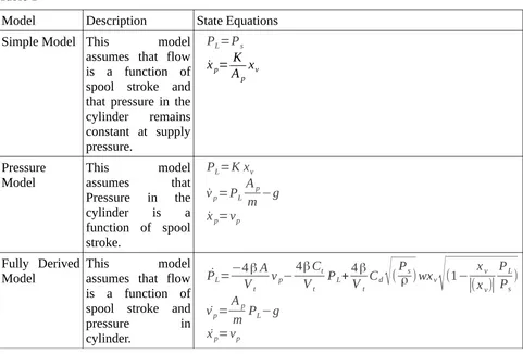
Three models were developed to simulate hydraulic cylinders and motors. The models attempt to reconcile the actuator pressure, displacement and speed with the valve setting applied. Three models were derived and tested. The first model assumes that pressure remains constant, regardless of load, and that the valve regulates flow through the actuator. The second model assumes that the valve regulates the pressure in the cylinder, and that the flow is dependent on the dynamic movement of the load. In the third model, actuator speed, displacement and internal pressure are all treated as system states and valve displacement has a non-linear relationship with internal pressure and oil flow. The governing equations for the models are derived located in Appendix A.
3.2 Hydraulic Actuator Simulation and Control
3.3 Simulation of Kinematic Arms
4 Interface Design and Development
4.1 Introduction
Most machines have operator interfaces which control the joint space. This is done to simplify the hydraulic control and results in one joint being moved by a single actuator, which is energised by a single control signal. Any additional control signals are usually present to meet some safety requirement. Regardless of whether there is a PLC or computer in the loop, it rarely closes it. Most machines require the operator to close the loop and conduct any transformations between the task action and the joint-space control. The level to which the joint space aligns with the task space, directly corresponds to the ease and intuitiveness of the interface.
4.2 Intuition – Task-space to Joint-space conversion
The level of intuition in an interface depends on how well the interface controls task space coordinates. Task-space coordinates are those directions and movements that directly support the completion of a task. These may be the same or at odds to the Joint-space coordinates. The Joint-space coordinates are directions and movements achievable by the joints of the machine. In most cases, the interface only controls the joint-space in a machine. The level to which those joints align with the task being done, will indicate how easy it is for the operator to complete a task with the machine. In rare cases, the operator interface will support the conversion between the task-space and joint-space if they are not aligned. If the interface does not support this conversion, and the operator only controls the joint-space of a machine whose joints do not align with the task, operation is only possible with great difficulty, risk, or requirement for a great deal of training and experience.
4.2.1 Common Mine Site Interfaces
In order to illustrate the points above, the dissertation will now examine three mining related machines and their interfaces, contrasting them by their intended task and by the interface provided to achieve it. Their ease of use will be evaluated by studying the length of operator training and importance of operator experience on effective and safe operation. The implications of this study on the Heavy Maintenance Manipulator's interface will be inferred and applied to the interfaces successfully developed and tested on operators.
4.2.1.1 Forklift
compared to the two controllable axes, steering and acceleration. This relationship means that any position and orientation can be achieved, subject to the path taken (S.M. LaValle, 2006). As a result, an operator is required to perform path planning. The mast elevation enables movement of the forks in the third dimension, so this expands the task space to include the placing of items at height. A forklift, therefore, has four degrees of freedom in its task space, three position and one orientation. This allows a forklift to complete a task such as picking up a pallet from the back of a truck, taking it into a warehouse and setting it on some pallet racking around 4-5m in height.
The tilt function could be described as a fifth degree of freedom, however, it is probably more accurate to describe it as an axis used in gripping the pallet. It allows the mast to be tilted back so the load does not slip off the forks. Similarly, the fork width function, common on forklifts, is more of a gripper function that allows the safe support of objects that may not all be a standard width. In this way the joint-space is highly aligned with the task-space of the machine, therefore, direct control of joint-space by an operator is valid and intuitive.
The formal training requirements for a forklift are three days(“Training and Licencing,” 2013)(“Forklift Training,” 2013), but require the operator to be at least 18 years of age and presumably competent at path planning.
4.2.1.2 Excavator with
Backhoe
An excavator conducting backhoe operations should also be examined. For fixed operation, the operator has four axes to control: swing, boom raise and lower, arm raise and lower and bucket flex, as shown in Illustration 6 . The four axes are partially aligned to the task-space. Bucket digging requires the bucket to subscribe an arc in order for it to fill with material. Illustration 5: Axes present in typical forklift
(“Forklift,” n.d.)
The digging arcs are supported by the machine's revolute joints. However, the joints are also required to position the bucket in both the radial and vertical space from the swing axis. The position of the bucket is defined in cylindrical task-space coordinates. Therefore, unlike the forklift, an excavator's task space does not correspond directly with the joint-space of the boom-arm-bucket arrangement. In excavator/backhoe operations, the operator controls only joint space. However, the system is determinant, there are four joints, and four degrees of freedom in the task-space. There is only one joint-space solution for a given bucket position and pitch. As the operator drives the machine in a joint-space which is not aligned with a task space, he/she has to convert between joint-space and task-space. To know what combination of boom angle, arm angle and bucket angle will be required to achieve a given bucket position and pitch requires training and practice. Typical excavator training times are five days for a full course certification(“Excavator Training,” 2013) (“Excavator Course - RIIMPO320B,” 2013). Additionally, it has been shown that operator experience has a significant effect on the productivity of an excavator, due to an experienced operator activating more than one joint at a time. It seems that the ability to transform between task-space and joint-space improves with experience(K. Hughes and X. Jaing, 2010, p. 419).
4.2.1.3 Dragline
A third and final example of user interface which includes different characteristics is that of a dragline. For fixed digging, the operator has three controls, Drag, Hoist and Swing. The task-space of the machine consists of four degrees of freedom, three of position and one of bucket carry angle. The Bucket potentially has a full six degrees of freedom, if tensions in the twin ropes is ever unequal, but the task space of the machine is only defined in four dimensions: three cylindrical position coordinates and the bucket carry angle. As the operator only has three controls of a joint-space that consists of Drag, Hoist and Swing, the system is under-determined (P. Ridley, 2004, p. 17). This means the operator does not have full control of all four task-space degrees of freedom at any operating point. The under-determined nature of the system manifests itself as lines of constant carry angle that are relatively fixed (depending on bucket load distribution(P. Ridley and R. Algra, 2004, p. 1001)) as shown in Illustration 7. Without using bucket inertia to expand the task-space, operators have a fixed envelope of where they can dump the bucket, i.e. achieve a carry angle of -90deg by releasing tension on the Dump Ropes. In order to conduct digging, the bucket must be constrained by the ground and allow the Drag tension to pull the bucket full.
The position of the bucket radially and vertically is dependent on a combination of Drag and Hoist Tensions, which are also tied to the carry angle of the bucket. It is only through Illustration 7: Representation of lines of
the design of the Dragline system that the carry of the bucket corresponds to the intended method of operation or task-space of the machine. This system requires transformation by the operator from the Drag and Hoist joint-spaces to a non-linear position and indeterminate carry-angle task-space. Of the three machines examined, due to the operator interface complexity, dragline operators can be expected to require the most training and experience for effective production.
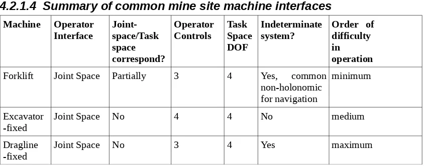
4.2.1.4 Summary of common mine site machine interfaces Machine Operator
Interface Joint-space/Task space correspond?
Operator
Controls Task Space DOF
Indeterminate
system? Order of difficulty in
operation
Forklift Joint Space Partially 3 4 Yes, common
non-holonomic for navigation
minimum
Excavator
-fixed Joint Space No 4 4 No medium
Dragline
[image:19.595.114.538.193.359.2]-fixed Joint Space No 3 4 Yes maximum
Table 1: Summary of common mine site machinery task-space, joint-space and operator interface relationships against difficulty of operation.
A summary of common site operator interfaces that have been examined is contained in Table 1. It is obvious that the ease of effective machine operation is due, in part at least, to how well the operator interface corresponds to the task being undertaken. If the task-space and the operator input correspond, a large number of degrees of freedom may be manipulated relatively easily. Where a machine is controlled in joint-space, particularly one which does not correspond to its task-space, the operator is required to close the loop and perform the conversions between the joint-space of the controls and the task-space of the machine. The conversion requires training and experience. Typically, the less the joints correspond to the task, the more training is required for effective and safe operation.
The next section will examine a serially-linked manipulator with a tool at the end. The relationship between the position of the joints (the joint-space), and the position of the tool in six degrees of freedom (the task-space) will also be evaluated. This relationship is determined by forward kinematics when converting from joint-space to task-space, and the change in the task-space can be estimated from the change in the joint-space through a mathematical device known as the jacobian.
4.3 Solving the Jacobian Matrix
change in tool position or orientation?” Expressed differently: “What “twitches” in joint angle are required to change tool position or orientation by a small amount?” The answer lies in the Jacobian Matrix.
For the next section, it will be assumed that the arm has only six joints. This is the exact number of joints to ensure that there is only one solution to our query. A full description of position consists of three values; x, y, and z, and full orientation description consists of three values; θ, ϕ, γ. If there are six joints, any change in tool position or orientation must be the sum of tool changes due to variations in each joint. This creates six equations describing that relationship, one for each joint. This relationship is also known as the Jacobian. The changes in the tool become the six unknowns. As there are six equations and six unknowns, the system is determinate and there is only one solution for the unknowns.
The Jacobian is the matrix of first order partial derivatives of a vector valued function (“Jacobian Matrix,” 2013). In this case, it is a matrix of how each of the tool orientation and position coordinates change with slight changes in each of the joint angles. Tool change over joint change becomes the partial derivative. As stated above, it describes the change of tool position as the sum of the tool position/orientation changes due to changes in each joint. It is expressed below:
J=
[
∂x∂θ1
∂x
∂θ2
∂x
∂θ3
∂x
∂θ4
∂x
∂θ5
∂x
∂θ6
∂y
∂θ1
∂y
∂θ2
∂y
∂θ3
∂y
∂θ4
∂y
∂θ5
∂y
∂θ6
∂z
∂θ1
∂z
∂θ2
∂z
∂θ3
∂z
∂θ4
∂z
∂θ5
∂z
∂θ6
∂β ∂θ1
∂β ∂θ2
∂β ∂θ3
∂β ∂θ4
∂β ∂θ5
∂ β ∂θ6
∂φ
∂θ1
∂φ
∂θ2
∂φ
∂θ3
∂φ
∂θ4
∂φ
∂θ5
∂φ
∂θ6
∂ γ ∂θ1
∂ γ ∂θ2
∂ γ ∂θ3
∂ γ ∂θ4
∂ γ ∂θ5
∂ γ ∂θ6
]
It can be used to determine the small changes in tool position and orientation δx given small changes in joint angle δ θ , both 6x1 vectors as shown below:
δx=Jδ θ
More importantly, the expression can be inverted to determine the machine operator's query: “What changes in joint angle are required for small changes in position or orientation?”
δ θ=J−1δx
the shur's complement (“Shur Complement,” 01 Sep 13). Care has to be taken when dealing with a determinate system to avoid singularities. Singularities are parts of the joint space for which a large change in joint angle only causes a small change in tool location. They are difficult to detect and often rely on a careful off-line analysis of all spaces where the singularities occur, either through analytical or numerical means.
4.3.1.1 Contemporary way for Dealing with Redundant Manipulators
The case has been examined where there are six axes for the six position and orientation components. However, a six axis manipulator can be limited if a particular joint angle cannot be achieved. As we have already examined, there is only one set of joint solutions for a given position and orientation, so if a solution cannot be achieved because a joint cannot change as desired, the possibility of achieving the tool target position and orientation would be undermined. By adding an additional joint to the arm, the number of viable solutions for position and orientation can be increased, however the system is now over-determined, and one of the possible solutions must be chosen. In fact, there is an infinite number of angle changes over two or more axes (for a manipulator without limits) that can completely cancel each other out, this is known as the null space of the manipulator. It exists whenever there is a non-square matrix with full rank that requires inversion. Therefore, if it is not dealt with appropriately, the manipulator may not move at all!
This project developed a novel procedure for avoiding the null-space and attaining other desirable attributes. Firstly, we will examine how redundancy is handled in contemporary manipulators. A jacobian can still be constructed for a seven axis system, it is now becomes a rectangular 6x7 matrix:
J=
[
∂x∂θ1
∂x
∂θ2
∂x
∂θ3
∂x
∂θ4
∂x
∂θ5
∂x
∂θ6
∂x
∂θ7
∂y
∂θ1
∂y
∂θ2
∂y
∂θ3
∂y
∂θ4
∂y
∂θ5
∂y
∂θ6
∂y
∂θ7
∂z
∂θ1
∂z
∂θ2
∂z
∂θ3
∂z
∂θ4
∂z
∂θ5
∂z
∂θ6
∂z
∂θ7
∂β ∂θ1
∂β ∂θ2
∂β ∂θ3
∂β ∂θ4
∂β ∂θ5
∂β ∂θ6
∂β ∂θ7
∂φ
∂θ1
∂φ
∂θ2
∂φ
∂θ3
∂φ
∂θ4
∂φ
∂θ5
∂φ
∂θ6
∂φ
∂θ7
∂ γ ∂θ1
∂ γ ∂θ2
∂ γ ∂θ3
∂ γ ∂θ4
∂ γ ∂θ5
∂ γ ∂θ6
∂ γ ∂θ7
]
A pseudo inverse can be calculated for this matrix and full rank of the matrix can be expected as each of the arm joints are physically independent elements and do not drive each other. As a result the Moore-Penrose pseudo inverse J† can be calculated directly from:
J†
=JT
(JJT
where JT is the matrix transpose. This pseudo inverse can be used directly, however it is usually combined with a weighting matrix W to deal with singularities and to minimise performance metrics. There is no set formula for determining the weighting matrix and it selection is rather arbitrary. If W is to be used then it is typically used to weight the pseudo inverse in the method shown below:
JW†=W−1JT(JW−1JT)−1 (L. Beiner and J. Mattila, 1999, p. 176)
This weighting matrix adjusts the null space of the jacobian. It adjusts these in order to achieve some performance metric, such as lower joint torque, kinetic energy, avoiding joint limits and so on. Typically, developing this weighting matrix is specific to the manipulator and its current configuration, therefore can be somewhat computationally involved in its determination and requires updating as the manipulator moves.
4.3.1.2 Conclusion
Understanding the kinematics of an arm is useful for both simulation and control. The Forward Kinematics converts the joint space to the world coordinate system task space. The inverse kinematics is much harder to calculate, but if a starting orientation is known, then joint space can be modified to achieve a task space goal. When dealing with redundant joints, the contemporary methods require a weighting matrix which can be computationally intensive to determine as it changes when the manipulator moves. This dissertation will now propose a more pragmatic approach to the elimination of the redundancy.
4.4 Novel Heavy Maintenance Manipulator Interfaces
4.4.1 Novel Method for Resolving Manipulator Joint
Redundancies
In this project, redundancy was handled in a novel way, avoiding the complexity of an overly analytical weighting matrix. The goals of this novel method were primarily to minimise the chance of singularities due to HSEC consequences of large, impromptu joint changes and to provide workable solutions to the problem.
The method treated each joint as being fixed in turn, and calculated a square jacobian for each of these cases using the remaining six joints. The joint-space changes were calculated for each of these cases, inserting a zero joint change for the joint that is held fixed. Finally, the set of seven joint changes results are compared and the case that has the smallest, maximum joint change is chosen. This ensures to steer us around the singularities which have been identified as large joint changes for a given tool change. This method is shown in Illustration 8.
Where seven different joints can be made redundant, there will be seven possible solutions (cases). It is important to note that once the seven possible solutions are calculated, the method for selecting the redundant joint can be based on what ever criteria the designer desires. In this case, the redundant joint was chosen to minimise the size of the joint changes required (thus singularities), but other criteria may be chosen to minimise joint torques, avoid limits or avoid obstacles. As the manipulator only has position sensors fitted, such alternative criteria could not be implemented. In the general case, where we have a manipulator with n redundant joints, where:
n=j−m
where j is the number of joints and m is the number of degrees of freedom. The operational complexity increases exponentially with the number of possible solutions equal to:
(m+n)n
This does not include the computation required to implement the selection criteria. Thus the computational cost can dramatically increase with every additional redundant joint. This may not be such a problem as the cost of computation is relatively cheap.
4.4.2 Application of Task space conversion on real interfaces
Two methods for calculating the joint-space of the manipulator from the user inputs were used in the three main interfaces successfully developed in this project:1. Master Arm Interface, 2. Joystick Interface, and 3. Sensor Interface.
4.4.3 Master Arm Interface
4.4.4 Joystick Interface
In the Joystick Interface, joysticks are utilised to gather user task space input. The joystick axes were aligned to the direction of the task-space axes being controlled. For example, if the operator wants to move the tool left, a joystick will need to be pushed left. If an up movement is required, a joystick is pushed upwards.
In order to achieve this effect, software implements our task-space to joint-space conversion. It treats the measurement of the joystick as a task-space change and calculates the appropriate changes in joint-space as described. Task-space control of this sort has been used on simpler manipulators before and has shown to improve the performance of novice and experienced operators (A. Hansson and M. Servin, 2010, p. 1074).
4.4.5 Sensor Interface
In the Sensor Interface, an acceleration sensor and a magnetic sensor were used to determine the orientation of a handheld device (android phone). The touchscreen interface implemented methods for indicating task-space position and orientation change of the tool. Once these commands were input, the same software framework as per the Joystick Interface was used to determine the appropriate conversion to joint-space.
4.5 Feedback
An important aspect of operator interfaces is the provision of feedback to the operator. In most existing cases this requirement includes a visual reference, either a light or display, for load and equipment state. In hydraulically actuated machines, where the operating levers directly actuate the hydraulic valves, the operator can feel and hear the amount of fluid flow through the valve. This assists the operator to assess the required spool displacement required to achieve a particular level of joint movement, resulting in a slower, smoother joint movement (K. Hughes and X. Jaing, 2010, p. 419).
In electrical interfaces, force feedback is typically not incorporated into the interface. This results in lower operator fatigue and faster manipulation of the joints (K. Hughes and X. Jaing, 2010, p. 417). As a consequence with no other controls in place, electronic joint control interfaces can result in a higher level of wear and fatigue on the mechanical structure of the machine.
For the three successful interfaces developed, feedback consisted of: 1. lights on the interface to show the status of the interface, and 2. lights on the Slave Arm to indicate the state of the Arm.
During the course of the project, a number of other methods of feedback were investigated but were not ultimately incorporated into the interface at this time. These require additional work to be successfully incorporated into the operator interface. These methods of feedback were:
1. force feedback on Joystick Interface;
3. video Feedback of arm movement.
These methods of feedback will be examined further.
4.5.1 Joystick Interface Force Feedback
The provision of force feedback for the Joystick Interface was applied through the direct connection of motors to the axes of a joystick. A PID signal adjusted the motor voltage, based on the position of the joystick. If a larger force were required, the reference for the PID would be moved so as to increase the motor signal and hence the force in a particular direction.
The configuration ran into a number of issues, particularly tuning the PID to overcome the large amounts of backlash and friction in the gears of joystick. The motor, even when geared, produced only a minimal level of force that was hardly felt by the operator. A key issue was the mechanical cradling of a 2-D gimbal that described x and y movement, in a structure that allowed movement in the z direction. The third joystick axis introduced additional mechanical complexity which was difficult to solve.
Overall, the use of a PID position-controlled motor in this way was not an effective option for achieving force feedback. A better option would have included a current sensor and direct control of the motor torque. A force controlled actuator would have been beneficial as long as the max force of the actuator could be felt by the operator. This requires larger motors, heavier gearing or greater mechanical advantage, all equalling a larger, bulkier interface. The use of low pressure hydraulics could have been an option as well, but at significant cost of actuators, valves and pressure sensors.
4.5.2 Master Arm Interface
A version of the Master Arm Interface was built that incorporated servo motors linked to actuate the joint through the use of tension springs. Position sensors were utilised to measure the joint angle, and an algorithm was arranged so that the force required on the joint was a function of the difference in angle between the joint and the Servos. When there is a difference, a spring would be extended creating a torque on the joint. The joint actuated in this way would have a limit of about 90 degrees before the springs would start to experience extension regardless of the difference in servo/joint angle. This was not such a problem as most joints were about 120 degrees in range and the force due to the spring extension past 90 degrees would serve to apply limits to the Master Arm.
4.5.3 Video Feedback
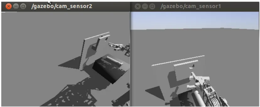
Video feedback is included in this section since the preferred arrangement has not been conclusively tested, though there are some aspects that will be shared here. The physical implementation of video feedback was achieved with the ROS image_transport and uvc_camera library allowing output of video feed to a normal computer screen or to an Android Tablet. It was found during simulation that a single camera is less effective because there could be no perception of depth thus tool position and orientation could only partially be evaluated by an operator. A two camera arrangement improves performance with depth much easier to perceive. A wider question emerges with multiple cameras: How should multiple cameras be mounted to best support the operator? This question is affected by a multitude of variables. In this we trialled two, twin video cameras in two configurations:
1. Configuration 1: A Head Camera and a Tool Camera, 2. Configuration 2: Two Head Cameras.
Configuration 1 has some problems, particularly when there is little variation in background and when the Hand Camera shows objects which are not visible by the Head Camera. This can lead to disorientation of the operator that can not be rectified by an of the information presented by the cameras. If the alignment axes are coaxial to the camera, lining up of the object by Configuration 1 is supported. This is dependent on the grip that can be achieved on the object to be lined up. If it does not result in coaxial alignment between the camera axis and the task axis, the Tool Camera's utility is reduced.
In Camera Configuration 2, two head cameras providing some level of depth and height perception via a stereoscopic arrangement. The left-hand camera's field of view is orientated more towards the intended workspace, and provides a view that assists the estimation of vertical position and forward position. The right-hand camera is better suited for estimation of lateral position. These two views highlight one of the major problems with video feedback via cameras, namely the narrow field of view that does not cover the whole possible workspace. A solution would be to either install more cameras or develop a camera mount that revolves around the x and z axes (altitude-azimuth mount) to allow the camera to focus on some moveable point of interest.
Using multiple additional cameras would likely introduce bandwidth problems if they were streaming concurrently. This could be contrasted with extra control required of the camera platform. Bandwidth issues could be mitigated by automatic control of which cameras are streaming, and a moveable camera platform could be controlled to automatically focus on the tool.
Due to the relatively little evidence supporting one camera arrangement and the restrictions on fixed cameras, the video feedback question cannot be resolved without further testing. The preferred method of visual feedback at this stage will be to have the operator on the ground, out of harm's way, controlling the position and orientation of the manipulator without the help of a video feed.
4.5.3.1 System State Feedback
A light system was introduced on the operator interface and on the slave manipulator in order to provide direct feedback as to the state of the object. The operator interface light system is shown in Table 2.
Light State Interface Active Output Published
Green On Yes No
[image:28.595.69.483.109.280.2]Orange Actuated Yes Yes
Table 2: Light-based feedback for operator interface.
On the Slave Manipulator, the light system also identifies the system's state, but specifically for the manipulator. The Manipulator light system is shown in Table 3.
Light State Valves Active Joint State
Evaluated
Red Error No Yes – errors found
Blue On No Yes
Amber Joints Active,
Valves Active
Yes Yes
Table 3: Light based feedback for Slave Manipulator.
Overall, the light system is very effective in allowing understanding of a system's state, based on a quick glance at the light and an understanding of the state of the machine.
4.5.3.2 Conclusion
4.6 Design and Ergonomics
4.6.1 Common Electrical Framework
For the electrical and computational support of all interfaces, a common electrical circuit was designed. This circuit supported both the Master Arm Interface and the Joystick Interface, as well as the common Actuation Button, Tool Button and Status Light. The circuit was centred around the input/output device IOIO, which is a digital acquisition board designed for use with JAVA Android devices. It provides digital, analog and serial interfaces to an Android application via a USB connection. Due to the USB connection, there is a sizeable lag penalty compared to a typical embedded application for every input-output operation. There is however, a massive computational benefit in incorporating an Android platform, or any high-speed 32-bit device into an embedded application due to their additional computational power when dealing with floating point arithmetic. The Android platform provides many connection options utilising BluetoothTM and WIFI, though not normally a wired connection. Additionally, Android provides a ready made visual user interface through the LCD touchscreen.
options for the future. The block diagram for the circuit is shown in Illustration 12.
4.6.2 Master Arm Interface
4.6.2.1 Mechanical Design Considerations
The Master Arm Interface replicates the kinematics of the slave arm such that for any position or orientation pose, if the joint angles in the Master Arm are replicated in the slave arm, then a similar pose and orientation is expected from the Slave Arm. The test model was built out of acrylic plastic, and utilised 10 bit position controllers for joint angle reading. A grip was provided to reduce fatigue on the operator's hand. The Arm was fixed so that it would be close to the operator's left hand when seated. The operator could control the arm, minimising the level of interference with the operator's body. The Master Arm was modelled as 1:1 to a human arm.
The larger the Master Arm, the lower the gain of the system. That is, the further the joint is from the tool, the less it will move for a given task-space movement of the tool. The effect of this is that larger models will have a much higher level of precision compared to those which are miniaturised. This in turn impacts on the space required to utilise one of these interfaces, as longer link lengths require more movement to achieve a given output on the Slave Arm.
Each joint consists of a single or pair of non-lubricated plain bearings, with a loose fit tolerance. This allows relative ease of movement, and had an acceptable level of positional accuracy. It provided a very good precision in the joint sensors. Tool button, actuation button and status light were placed in a console for operation by the right hand.
Overall the mechanical design used for testing of the Master Arm Interface was capable and achieved a good response when tested on Coal Mining Workers for both intuitiveness and accuracy.
4.6.2.2 Electrical Design Considerations
Circuits specific to the Master Arm Interface are the joint encoders. These are the same encoders that are used on the Slave Arm. They provide a variety of outputs, but the SPI interface was specifically chosen as it provided measurements of absolute position. This eliminated the requirement for a high frequency update loop to poll the output of an Encoder or interrupt driven interfaces. Additionally there was no requirement for post-processing to produce an angle measurement which could experience drift from a zero position if measurements were lost. It also minimised the number of wires required as a common data, and clock bus could be shared between all encoders. The output from the encoders was very stable with only small changes to the Lower Significant Bit of around 0.1-0.2%.
The full SPI interface requires four wires to achieve full-duplex communications: Master In Slave Out (MISO), Master Out Slave In (MOSI), Clock (CLK) and a Chip Select (CS) for every slave device. For these encoders, the MOSI line was not required as the encoder didn't receive any information during normal operation and the MOSI line could be dropped.
To save data lines on the IOIO, the CS was provided by a 74LS138 3 to 8 line decoder/multiplexer to service seven slave devices using only three lines from the IOIO. The normal Chip Select pin in the software SPI module was not utilised. The arrangement used is shown in Illustration 12. The MISO and CLK lines were maintained on a common bus for all sensors. The hardware to connect the buses consisted of a single polarised header. Ribbon cable was used to provide a single line of cabling down the arm. Each CS had its own separate line down the arm.
The SPI output from an encoder is shown in Illustration 14. For each joint sensor the transmission begins with CSN switching LOW output. Data is then output from the sensor with each falling edge of an inverted CLK signal provided by the IOIO as master. This is known as SPI mode 3, and various other configurations of clock polarity and reading phase are possible in the protocol. The data consists of joint angular position, D9-D0, followed by six status bits. The status bits highlight any errors in the joint encoder including mag strength, linearity, and chip readiness. A parity bit to ends the transmission to assist in detection of transmission errors. The transmission finishes when CSN is made HIGH, the next transmission can begin within 0.5μs with CSN being dropped LOW.
4.6.2.3 Software Design
For this interface to work, two software nodes are utilised, one to read the Joint Sensors on the Master Arm, and the other to apply position control to the Slave Arm. For the master arm the software runs a simple setup routine and then engages in a loop. In the setup, the software reads the sensors, to determine the zero position for the Master Arm. Therefore, the Arm must be positioned at start time to the zero position of the Slave Arm. The software then follows its loop of:
1. reading its sensors,
2. applying the zero position to get angle change from a starting pose, and 3. publishing these positions to a joint controller as reference positions.
The Joint Controller /controller_cpp subscribes to these reference positions and also to Joint Data from the Slave Arm. It applies PID control and publishes valve commands to the slave_node, controlling the actuators as shown in Illustration 15. This forms a non-realtime control loop and is typically run on the same computer as the slave_node in order to avoid connection issues.
Illustration 14: Voltage signals along the Chip Select, Clk and MISO lines for the Joint Encoder SPI (“AS5040 Datasheet,” 2009, p. 33)
4.6.3 Joystick Interface
4.6.3.1 Mechanical Design Considerations
The Joystick Interface utilised a number of twin axis thumb joysticks to receive operator input. The Thumb Joystick is utilised on a number of commercial interfaces, predominately game controllers. They are spring loaded, always returning to centre, can be manipulated by one finger, giving the possibility of manipulating more than one thumb joystick with one hand. The spring also gives them a good 'feel' so that even if there is no direct feedback, the operator still has a sense when the joystick is close to its limits. The Joysticks are small and light, making them suitable for portable interfaces and also to mount in a variety of configurations. This is important so that the joystick is aligned to the task-space of the user.
Two options were tested for aligning the joysticks with the task axes. Remembering that the six task degrees of freedom are left/right, forward/backward, up/down, roll, pitch and yaw. They represent the translational and rotational movement about three axes x, y and z. The first option aligned three joysticks orthogonally to each other around a central mount. Each joystick axis therefore represented either a translation or a rotation about the axis the joystick was aligned to as shown in Illustration 16. The three joysticks were designed to be operated by one hand, leaving the other hand free for other tasks. This arrangement had poor ergonomics, in particular due to the limitations of reach of an operators hand. Also, it didn't equally divide the workload between the available hands, making a five fingered hand control six axes!
The second option divided the workload between both hands. The left hand controlled orientation, and the right hand controlled position. To achieve this, four thumb joysticks, two for position and two for orientation, were used to replicate the six task degrees of freedom. This gave four axes for three position axes, and four axes for the three orientation axes. The joystick pairs were mounted orthogonally to each other and the joystick axes controlled the aligned position or orientation axis. It allowed the operator to directly actuate his task-space intentions on the interface. It also divided the workload, allowing control to be achieved by only two fingers on each hand leaving the others to push buttons and support the interface. The interface had similar ergonomics as a game controller, except that it has four joysticks instead of two. The interface is shown in Illustration 17.
4.6.3.2 Electrical Design Considerations
The electrical design is relatively simple with the thumb joysticks forming a linear voltage divider, read by the Analog to Digital Converters (ADC) on the IOIO. The IOIO has sixteen ADCs available and six are reqired to read the Thumb Joystick position. The joysticks are supplied with the ADC ref voltage of 3.3V.
4.6.3.3 Software Design
As the software is required to conduct the transformations between the task-space input and the joint-space control of the machine. The preferred software arrangement splits the hardware interfacing and the transformation algorithm into separate nodes. This allows the same transformation algorithm to be used with a variety of interfaces that publish the operator's task-space intentions.
The /Joystick_node does the hardware interfacing and runs a setup routine followed by a loop. During the setup routine, the thumb joysticks remain in a the neutral position so that this reference position may be read and recorded to become the zero point for the joystick axis. In the loop, the thumb joysticks are read and the zero point subtracted from them to get a signed value indicating a positive or negative direction in the task-space axis. The range of joystick movement was broken up into three bands representing a Deadband, Fine and Coarse movement. This minimised the occurrence of drift in the results and made the input more robust. The difference
in gain from fine to coarse movement was a factor of five. The measurements of joystick position were then published to the /HMM_Cartesian_Interface_node over the /HMMInterface/dtask_space topic.
The /HMM_Cartesian_Interface_node calculated the jacobian and dealt with the redundancy as shown in Section 4.3. The node subscribed to the /joint_states msg that was being published by the /rate_controller_cpp. The /joint_states topic described the position, velocity and torque of each of the joints. This was used to update the kinematic model in the /HMM_Cartesian_Interface_node to the same position state as the real arm, hence ensure the inverse jacobian algorithm was accurate for the current pose of the arm. The node calculated the joint changes as per the redundancy algorithm and published them to /rate_controller_cpp which was an open loop velocity controller of the joint actuators. Rate_controller_cpp applied the joint change twitches as valve signals to the Slave Manipulator.
4.6.4 Sensor Interface
4.6.4.1 Mechanical Considerations
The sensor interface utilises an Android device equipped with a gravity and magnetic sensor which allows the measurement of all the orientation axes. The touchscreen provides three buttons for control of the input: a forward arrow, a backward arrow and a button labelled “Orientation” as shown in Illustration 19.
To achieve position movement, the operator aligns the arrows with the intended direction for movement and then presses the arrow that corresponds to the direction required. Software measures the orientation of the device and determines the positional changes due to a movement along the line of action indicated by the orientation of the device.
When the Orientation Button is pressed, any subsequent change in orientation of the device becomes the change in orientation task-space. This amount is proportional to that physical change in orientation. A gain is applied to improve the sensitivity of the input.
The only Android device that was available with the appropriate sensors was a 10inch tablet. This tablet was somewhat heavier than the 4 inch device that was desired. A 4 inch device could be supported in the palm of the operator's hand and easily manipulated in order to change orientation. An additional problem identified with this interface was that the Android User Interface (UI) does not record the pressing of multiple buttons at the same time. As a result, a physical Tool Open Button and Actuation Button were still required. It would be envisaged that the additional buttons would be integrated into the single device.
4.6.4.2 Electrical
Considerations
As the interface is already packaged in an Android Device, only the Interface Status Light, Tool Open Button and Actuation Button were required and they were implemented as part of the common electrical arrangement.
4.6.4.3 Software
Considerations
Whereas the software for previous interfaces ran on one main thread, this interface required two threads to share data. A user interface thread which measured sensor output and a ROS thread that handled ROS communications. The sensor packages were read each time a change was detected. Two sensor packages were read: The Gravity sensor and the Orientation sensor.
The Gravity sensor measured the gravitational acceleration along three orthogonal axes which correspond to the x, y and z directions. The directions are relative to the Android device, hence, if the device is held flat, then the readings would be x=0, y =0 and z=-9.8. The units of the sensor are m/s2. Pitch forward increases the y value and roll to the right or left increases x value. These sensor values are equal to gsinθ , where θ is the angle around an axis. Hence there will be a sinusoidal output in the axes as the tablet is rotated at a constant rate. This means that the value from the sensor can be used directly and no further geometric functions are required. The Orientation Sensor also measures yaw based on the relative position of magnetic north to the tablet, and the output from the gravity sensor (“Position Sensors,” 2013). The units are in radians. The Sensor Interface establishes a zero direction of the Orientation Sensor on startup which is taken as the reference for the positive y-axis (forward face) of the Slave Manipulator. The direction the top of the Android device is facing at application initialisation becomes the positive y-axis for Illustration 19: Screenshot of Sensor
the interface. The difference from this reference direction is then included in the amount of x and y task-space movement as per below (for a forward arrow push):
dx=(1−gy
g)sin(magz−magz0) dy=(1−gy
g )cos(magz−magz0) dz=gy
g
Where gy is the acceleration value along the y-axis, magz is the current yaw angle and magz0 is the reference yaw angle when the application was first started. For determining task-space orientation change, the reading when the Orientation Button is pressed is stored. Task space orientation change becomes the change in orientation from that initial value.
droll=magy2−magy1 dpitch=magx2−magx1
dyaw=magz2−magz1
The subscript 1 refers to the reading when the Orientation Button is first pressed and subscript 2 refers to the sensor value at some time after with the Orientation Button pressed. The change in orientation, droll, dpitch and dyaw stop being evaluated once the Orientation Button is released and reset to new values.
4.6.4.3.1 ROS Thread.
Once the task-space directions have been evaluated, they are passed to /Sensor_node in a separate CPU thread via a shared memory application object. Once transferred to the /Sensor_node the operator's task-space control signals are published to the same /HMM_Cartesian_Interface_node that is used in the Joystick Interface. The remainder of the software is as per the Joystick Interface.
4.7 Interface Testing and Results
In order to evaluate the current range of human machine interfaces (HMI) to allow tele-operation of the Heavy Maintenance Manipulator, testing was conducted to evaluate their effectiveness with the target operators. The three interfaces were the Master Arm Interface, Joystick Interface, and the Sensor Interface. These were tested on Mine Employees using two simulated maintenance tasks.
4.7.1 Aim
4.7.2 Method
4.7.2.1 Simulating Tasks with ROS and GAZEBO
Having a model that works within a Force-Dynamic simulation, which includes collision modelling, allowed some of the tasks of the arm to be examined. These tasks include: picking up a pin and inserting it into a double clevis, and rotating a Hoist Chain. These task-based simulations allowed the study of: the arm range of movement, the requirements for effective grasping, and the ability of having only a single arm to perform the required tasks.
4.7.2.1.1 Pin Place Task
One of the dragline rigging maintenance tasks that was focussed on was inserting a pin. This is a common task and was replicated by a simulation of inserting a drag pin into a hole in a vertical wall. This task demonstrated a number of key capabilities in the simulation: how an interface can accurately position and orientate the gripper, and how an interface can then align the gripped pin to the target hole. This task required a couple of extra models beyond that of the manipulator. These included a 6 inch pin, and a wall with a double clevis, which is similar in arrangement to a trunion mount on a dragline bucket. The starting layout is shown in Illustration 6.
4.7.2.1.2 Hoist Chain Rotation Task
This task attempted to replicate the rotation of a Hoist Chain which was being held in a double clevis. This required the chain to be removed from the clevis, rotated 180 degrees and reinserted into the clevis. The task tested the interfaces and grippers as before, but also tested to see if the manipulator has the range of movement capable to complete the task using just a single arm. The layout is shown in Illustration 7. An interesting point to note is in the simulation of chain.
Normal chain-links have six degrees of freedom, however to simplify simulation, and to improve simulation performance, the joints between the links were modelled with only two axes. This saves computational power and allows the simulation to run closer to real time. This gave the chain some of its more common movement, but not the full movement that would be observed by letting the chain fall in a heap. Illustration 22 shows the joint axes used in the simplified hoist chain model. In all links other than the top link, both the green and red axes are modelled as rotational joints. The top link rotates to the world via the blue axis.
If the full six degree of freedom movement of chain-links relative to each other is desired, a hoist chain can be modelled without any joints but with self-collision on. This meant that the simulator dynamics engine would have to determine the movement of the links based on collision modelling. This successfully modelled the chain with behaviour that was very realistic but at a greater computational cost. The cost of
modelling the links using collision modelling made the Illustration 22: Hoist Chain model showing joints
simulation run about 250 times slower than the simplified version. The simulation ran at about 2% of real time, which was not suitable if being used as an environment for testing of operator interfaces.
4.7.2.1.3 Process
Each of the interfaces was applied to the two maintenance situations outlined above:
• the task to place a pin into a double clevis, and
• the task to remove and rotate a suspended hoist chain and place into the clevis.
The Joystick Interface during this testing was the Mk I joystick, with the Mk II being developed as a result of the test results. Operators were asked to complete the task and questioned for subjective information regarding the ease of use of the different interfaces. The comments regarding each interface were recorded after each test and a comparison between the interfaces was conducted using a questionnaire.
After the intitial round of testing was completed, the results were used to redesign and debug the interfaces and there was a second retest of the interfaces.
4.7.3 Results
The five individuals were made available for the initial testing of the interfaces. Their qualifications and experience are as follows:
Serial Operator
Trade Machinery Qualifications Computer Literacy
1 Fitter Nil. Nil
2 Boilermaker Forklift, Overhead Crane, Telehandler
Game Consoles
3 Fitter 20ton Crane,
Bucket Truck, Forklift
Minimal
4 Rigger
Supervisor
20ton Crane, Elevated Work Platform, Grader
Office suite, GSAP
5 Fitter 20 Ton Crane. Minimal
Comments Regarding the Interfaces
Interface: Positives Negatives
Master Arm • Wasn't too bad to control.
• Read the signal and did what you wanted.
• The whole concept is very good and would be useful
• Interface was pretty responsive.
• Gripper open button, could be a gripper close button. But having it as a gripper open button is safer. Probably having it as a toggle open, toggle closed would be more suitable.
• Easy enough.
• May help if the gripper button were on the master arm.
• It did what you wanted it to do.
• Working off your arm movements is the biggest positive.
• Was able to complete the pin-place task.
•
dominant hand.
• The dead-man (actuation switch) could be improved by possibly being actuated by foot.
• Didn't know where the limits were.
• Delay – but can get used to it
• Needs a grip to handle the master arm.
• Delay, if it could be eliminated that would be handier.
• Hand grip needs to be in place.
• Had difficulty with Joint 5, getting it to move.
• Getting the 5th Joint to move was difficult
• Size of arm could be improved, something could attach to your arm.
• Gripper could be redesigned, grab once and that's it. A Magnet would be a good alternate gripper or some sort of pincer
• Clamping arrangement. Need a cradle and a ram setup for the tool.
• Controls not to be too touchy, gradual control that you can react to.
Joystick
Interface •in placeDoesn't have to be held
• Would be good if you could get it to be responsive.
• Park a tele-handler and use, and possibly remove from the cab to stand next to rigger for better communications.
• The interface wasn't too bad in finding a solution it was just that I would like the ability to switch between the computer controlling joint space and the ability for the operator to
• Has a bit of a longer training liability
• Interface is a bit tricky in having enough fingers to operate the joysticks. Could be fixed by having more thumbsticks for two hands.
• Controls not responsive.
• The joystick arrangement is awkward.
control joint space.
• Joystick would be better if it did what you wanted it to do.
• Felt