Creep-fatigue behavior of aluminum alloy-based metal matrix
composite
Daniele Barbera
a, Haofeng Chen
a*, Yinghua Liu
baDepartment of Mechanical & Aerospace Enginnering, University of Strathclyde,Montrose Street 76, Glasgow, G1 1XJ, UK bDepartment of Engineering Mechanics, Tsinghua University, Beijing, 100084, China
Abstract
Metal Matrix Composite (MMC) represents a valuable option as structural material for different type of structures and components. Despite this they struggle to become widely adopted due to expensive manufacturing process and complex microstructural behaviour. When subjected to cyclic load conditions the structural response of MMC is not trivial, and becomes even more difficult when high temperature load is involved. Different failure mechanisms would happen and they are originated by the different material properties between the fibre and surrounding matrix. Among all, the mismatch of thermal expansion coefficient is recognized to be the dominant one. The significantly differing coefficients of thermal expansion between ceramic and metal give rise to micro thermal stresses, which enhance the initiation of matrix micro cracks. Their performance under varying load and high temperature is complex, and hence it is difficult to have a clear understanding of the structural responses, especially when fatigue and creep damages become the main failures of MMCs. To improve current understanding of the relationship between creep fatigue interaction of MMCs, the history of thermal and mechanical loading, and the creep dwell period, a highly accurate but robust direct simulation technique on the basis of the Linear Matching Method (LMM) framework has been proposed in this paper, and been applied to model the fatigue and creep behaviour of MMCs. A homogenised FE model is considered in all analyses, which consist of continuous silicon carbide fibres embedded in a square 2024T3 aluminium alloy matrix array. Various factors that affect creep and fatigue behaviours of composites are analysed and discussed, including effects of the applied load level, dwell period and temperature on the MMC’s performance. The effects of reversed plasticity on stress relaxation and creep deformation of MMC are investigated, and the behaviours of cyclically enhanced creep and elastic follow-up are presented. A detailed study of the creep ratchetting mechanism is also performed with the concentration on the impact of temperature and different loading conditions. The accuracy of the proposed method has been verified by detailed incremental finite element analyses using the commercial finite element solver Abaqus. Such verifications further improve the understanding of the failure mechanisms identified and discussed in this work.
Keywords: Linear Matching Method (LMM); Creep; Fatigue; Cyclic Plasticity; Metal Matrix Composite (MMC)
1.Introduction
The increasing demand of machines operating at high level of efficiency requires high operating temperatures, and for particular application also a light weight design. Metal Matrix Composites (MMCs) are composite materials which are capable of delivering the aforementioned requirements. Different types of reinforcement can be introduced in the metal matrix, including randomly dispersed particles, short fibres and homogenously aligned long fibres. This work is concentrated on the latter type of reinforcement, which has a high strength on the fibre direction and low weight ratio as well. However these advantages are seriously downsized by creep behaviour, thermal fatigue, manufacturing processes and environment problems like oxidation [1]. Especially creep fatigue behaviour becomes an area of research interest, due to the lack of a unified and universal method to asses it, although different standard codes were developed for the assessment of creep fatigue life of high temperature component, including ASME BPV code and UK R5 [2, 3].
When creep is present, the structure’s response to a cyclic loading condition changes dramatically [4-6], with
respect to the low temperature case. Due to the induced residual stresses by creep and plasticity, a closed stress strain cycle may be formed when the reverse plastic strains completely recover the inelastic strain created during loading and creep dwell periods. With this situation, the lifetime of the MMCs is dominated by the combined damages from cyclically enhanced creep and increased fatigue by the stress relaxation during the dwell period. Alternatively, the hysteresis loop may become non-closed if the creep strains become too large for the reverse plastic strains to recover or vice versa. This leads to a critical failure mechanism called creep ratchetting, which is similar to the plastic ratchetting, for both the inelastic strain will be accumulated during each load cycle. However, the accumulation of inelastic strain for creep ratchetting is driven by either the creep strain or stress relaxation during the dwell period. In order to evaluate creep fatigue interactions and combined damages of MMCs under cyclic load and high temperature condition, various factors that affect creep and fatigue behaviours of composites need to be investigated, including effects of the applied cyclic load level, dwell period and temperature on the MMC’s performance.
Numerical simulations and modelling of fibre or particle reinforced aluminium based MMC have been performed by many researchers [7-15], in particular for the low cycle fatigue damage due to the cyclic plasticity, and creep rupture under high temperature condition. Traditional Finite Element Analysis was adopted, using for each case the most convenient material model, able to fit the experimental results. The micromechanical model was also used to study the size effect of fibre or particle on the MMC response. The Linear Matching Method (LMM), as a powerful Direct Method for the shakedown and ratchet analysis, has been used to investigate the shakedown and ratchetting response of fibre [16] or particle [17] reinforced MMC. However very little research focused on the creep fatigue interaction of MMC on a numerical prospective, and great efforts are necessary when simulating different interacting mechanisms.
The LMM has been recently extended for the evaluation of fatigue creep interaction and validated by [4, 5] and further used for a more practical application, i.e. creep fatigue life assessment of weldment [18-20]. But despite this no study on creep fatigue interaction of MMCs was performed by using the LMM. Therefore, the aim of this paper is to adopt the latest extension of the LMM [4] to evaluate the steady state cycle response of a silicon carbide fibre reinforced 2024T3 aluminium alloy based MMC, subjected to a cyclic thermal and mechanical load with a creep dwell between the loading and unloading phase. The interaction between all the aforementioned failure mechanisms is described and investigated for different loading conditions. This work is intended to be a general and fundamental attempt in understanding the microstructural response to high temperature environment and cyclic loading.
2.Numerical Procedures
2.1.General overview of the thermo-mechanical cyclic problem
Consider an Elastic Perfectly Plastic (EPP) body with a volume V and a surface S, which is subjected to a general cyclic load condition. On such body volume is applied a cycling temperature λθθ(x, t) instead on the surface a
constant load λpP(x, t) acting over part of the structure’s surface ST. The remaining surface is constrained to have no
displacement. The time variation considered over a typical cycle is 0tt. Corresponding to these loading histories there exists a linear elastic stress history:
ˆ e( , ) ˆ ( , ) ˆp( , )
ij x t ij x t p ij x t
(1)
where
ˆ
ij and
ˆ
ijp denotes the varying elastic stresses due to θ(x, t) and P(x, t), respectively. By selecting the proper values for λθ and λp a whole class of loading histories can be considered. The general stress field for thecyclic problem involves three different components, the elastic, the constant and the changing residual stress fields.
ˆ
( , ) e( , ) ( ) r( , )
ij x t ij x t ij x ij x t
The historyijr is the change in the residual stress during the cycle and must be zero at both the start and end of each load cycle, so that the stress and strain rate histories are asymptotic to the cyclic state.
2.2.An Extended LMM Direct Steady Cycle Analysis considering creep
In the present work an extended procedure of the LMM Direct Steady Cycle Analysis (DSCA) is adopted to evaluate the low cycle fatigue response with creep dwell. As in other works the LMM procedure requires as input a series of linear elastic solutions, generated at discrete time points within the cycle where a significant stress range occurs and hence the most relevant plastic strain. Such strategy is quite significant in terms of efficiency, because it saves computing time by targeting the steady state cycle directly and neglecting insignificant loading conditions which are assumed to lie in the von Mises yield surface, comparing with other cycle-by-cycle analysis methods which must consider the entire load history.
The aim of this extended DSCA procedure is to calculate the cyclic stress history at the steady state due to the accumulation of the residual stress field by either plastic or creep responses. The associated inelastic plastic or creep strains are also evaluated for the steady state load cycle. The extended DSCA procedure is based on a series of iterative cycles which are defined as m = 1, 2... M. Within each iterative sub-cycle, there will be a series of increments N, corresponding to each time points within the cycle ranging from n = 1, 2... N. Each individual varying residual stress
ijr( , )
x t
n m associated with each elastic solution
ˆ ( , )
ijex t
n at sub-cycle m will be calculated by the extended DSCA procedure in an iteratively way [4, 5]. Upon reaching a converged solution, the constant residual stress term from equation (2) can be determined by1 1
( ) ( , )
M N
r
ij ij n m
m n
x x t
(3)The accumulated residual stress for nthload instance at mth cycle of iterations can be defined as;
1
1 1 1
, ( , ) ( , )
m N n
r r r
ij n m ij n k ij k m
k n k
x t x t x t
(4)A flowchart of the LMM extended DSCA procedure is presented in Figure 1, which shows how to evaluate steady state plastic and creep behaviors of structures in an iterative way. For the load instance tn without creep dwell period, the plastic strain amplitude ijp( ,x tn) can be calculated by;
1 ˆ
( , ) ( , ) ( , )
2 ( , )
p e r
n ij n ij n
ij
n
x t x t x t
x t
(5)
where notation ( ' ) refers to the deviator component of stresses and
is the iterative shear modulus [4]. When adopting the Ramberg-Osgood (RO) material model, this plastic strain amplitude can be used to update the iterative yield stress. For the load instance with creep dwell periodt, the effective creep strainccan be calculated by equation (6) when considering a time hardening creep constitutive equation (17) in [4].1
1 1
( 1) ( )
1 1
( )( 1)
m
c s c
n n
c s
B n t
where B,mand n are the creep constants of the material.
cdenotes the creep flow stress, which is the sum of thestart-of-dwell stress
s and the residual stress
ijrinduced during the dwell period. The creep flow stress can beevaluated by equation (25) in [4], using the information of the creep strain rate at the end of dwell time, which is calculated by equation (23) and (24) in [4]. The calculation of the residual stress
ijrat each increment is throughthe solution of a formulated linear problem (10) as described in [4]. When the procedure is completed the residual stress field is obtained and the iterative shear modulus m( , )x tn is updated at each sub-cycle for each load instance
n
t
by adopting the linear matching equation;
1 ( , ) , ,ˆ , ,
R
y n m
m n m n e r
ij n ij n m
x t x t x t
x t x t
(7)
where m
x t,n
is the iterative shear modulus at the sub-cycle m for nth load instance.Ry( , )x tn m is the iterative von-Mises yield stress for RO material model or yield stress for the Elastic Perfectly Plastic (EPP) material model at load instance tn. This yield stress Ry( , )x tn m will be replaced by creep flow stress cwhen considering a load instance involving creep relaxation due to the introduced dwell period. At the end of each sub-cycle, the convergence will be checked. If the convergence criterion is not satisfied a subsequent sub-cycle starts, otherwise the results are outputted to provide all the crucial parameters for creep fatigue assessment.
1 1
1 1 1
ˆ ( , ) , ,
m N n
e r r
ij N ij nk ij km
k n k
x t x t x t
, r ijx tn m
n=N?
no yes
n = n+1 m = m+1
Start of DSCA analysis: Calculate elastic stress fields for N load instances for the load
cycle and set DSCA sub-cycle number m=1
Set sub-cycle iteration number n=1
Determine the augmented elastic stress field for load instance tnto start with:
Load instance for creep?
Calculate plastic strain amplitude for nth load instance
Eq.4
Convergence occurs?
DSCA outputs:
•Plastic, creep and ratchet strain solutions
•Stress solutions at each loading instance
•Total strain range of the hysteresis loop
no yes
yes no
Calculate creep strain rate and creep flow stress Calculate creep strain using the
time hardening creep law Eq.5
Calculate yield stress for RO material model or EPP model
Calculate residual stress at the load instance tnin mthsub-cycle
Update shear modulus using the LM formula with either yield stress or creep flow stress
Eq.6
3.Finite element model
3.1.Metal Matrix Composite numerical model
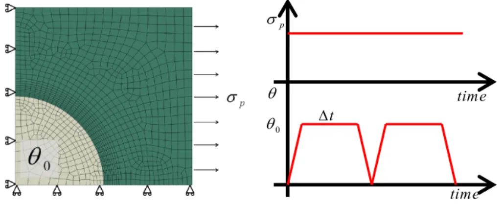
A long fibre reinforced MMC is analysed in this work. Due to the periodic dispersion of the fibres in the matrix a unit cell can be identified for the micromechanical modelling. The MMC unit cell is subjected to a constant mechanical load on the right external face and uniform cycling temperature from 0 to
0in the body (Figure 2). To assess the creep effect on the cyclic behaviour of MMC, a dwell periodtis introduced at each load cycle as shown in the Figure 2. Due to geometric symmetries a quarter of the unit cell is adopted with two planes of symmetry applied as boundary conditions, in addition to the plain condition on the two external faces to introduce the periodic constraints.The mesh is composed of 1039 8-node biquadratic plane strain quadrilateral elements, with a reduced integration scheme. The model is composed of two parts, a left corner spherical fibre and a surrounding metal matrix (Figure 2). Due to the interaction between the fibre and the matrix a refined mesh is adopted in the “Interaction Boundary” where the failure mechanisms are mostly expected.
Table 1 MMC material properties.
Al2O3 Fibre Al 2024 T3 Matrix
E MPa 450000 73000
0.15 0.33
6
4E 2.3E5
y MPa
10000 345
The material properties for both the matrix and fibre are reported in Table 1. Creep behaviour is evaluated using a time hardening creep constitutive relationship;
n
cr A tm
(8)where
n
is the stress exponent,m
is the time exponent for the primary creep stage and A is the power law multiplier. Creep is considered only for the matrix and the data for tensile creep is taken from [21] and reported in Table 2.t
0
time time
p
Table 2 Creep parameters A, n and m for 2024T3 aluminium alloy.
150⁰C 175⁰C 200⁰C 225⁰C
A 0.763 10 12 3.461 10 12 12
4.079 10
5.1186 10 12
n
3.246 3.299 3.395 3.5526m
0.303 0.573 0.535 0.5199In order to verify the LMM results, ABAQUS step-by-step analyses are used and the single operating load cycle consists of three ABAQUS load steps. The first one is a *STATIC step, which represents the loading phase where both temperature and mechanical load are applied. Then a *VISCO step is present to simulate the creep dwell time where mechanical load and temperature are constant. To implement equation (8) during the second step a user defined *CREEP subroutine is necessary, and the time-hardening formulation is adopted. The third step is a *STATIC step representing the unloading phase, where the mechanical load is constant and the temperature goes to zero.
4.Results and discussions
4.1.Effect of creep dwell on hysteresis loop
In order to provide a benchmark to define reasonable cyclic load conditions for the creep fatigue assessment of MMC, a shakedown limit interaction curve was calculated as shown in Figure 3 by using the LMM shakedown analysis method, where a reference uniform cycling temperature range from 0C to 0(where0200C
) is applied over the entire model. The ordinate and abscissa axes in Figure 3 show the temperature and mechanical load, normalised to the reference temperature 0and yield stress (345MPa) of matrix respectively.
0.00 0.10 0.20 0.30 0.40 0.50 0.60 0.70 0.80 0.90 1.00 1.10 1.20 1.30 1.40
0.00 0.10 0.20 0.30 0.40 0.50 0.60 0.70 0.80 0.90 1.00 1.10 1.20
Upper bound shakedown limit A₁
B₁ C₁ A₂ B₂
0
P y
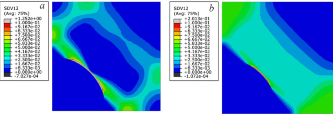
Figure 4 Effective plastic strains at different cycling load points
The adopted LMM analysis is also able to estimate the overall failure mechanism of MMC including the most critical location, by showing the contour of cyclic plastic strain range. Figure 4a shows the cell response to a cyclic load point at (0.7, 1.0) (Figure 3), whereas Figure 4b corresponds to the limit load. It is clear from Figure 4 that the “Interaction Boundary” is the most critical location, and this will be the location where the fatigue and creep damage will accumulate, ultimately initiating cracking in the matrix. The evaluation of creep fatigue behavior of MMCs is performed by a series of analyses considering six cyclic load points inside the shakedown limit: A1(0.25,0.875), A2(0.25,1.125), B1(0.7, 0.875), B2(0.7,1.125), C1(0.5, 0.875) and C2(0.5,1.125) as shown in Figure
3. If without creep effect, all these cyclic load points within the shakedown limit should exhibit shakedown behavior only. The aim of our analysis is to investigate how the cyclic behavior of MMC changes with creep response due to the introduced high temperature dwell period. In order to understand the creep-fatigue interaction, each load point is evaluated for different dwell times 1, 100, 1000 and 10000 hours, respectively.
Four hysteresis loops are generated and presented in Figure 5 for cyclic load points A1 and C1, where the blue and
red line correspond respectively to a dwell time of 1 hour and 100 hours at 175ºC. For a dwell time of 1 hour the closed hysteresis loop is present only for A1, instead for C1 a small total strain increment is present. Creep affects
both cases and enhances the unloading plasticity, but no plastic straining occurs during loading due to the total stress level since it is below the yield. The loop shape changes when a larger dwell time is considered, and non-closed loop behavior is observable also for A1. In Figure 5, the accumulation of total strain is entirely driven by the creep strain.
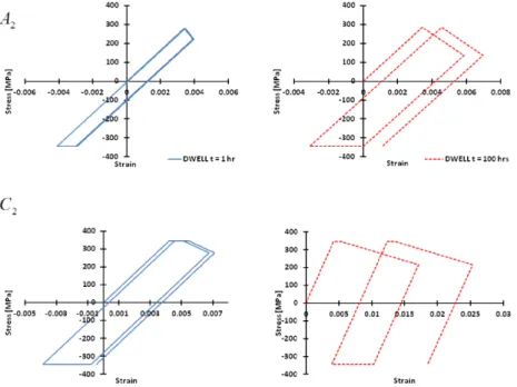
Figure 6 shows the MMC response to the cyclic load points A2 and C2 for different dwell times at 225ºC. The
load point A2 with smaller mechanical load also exhibits a closed loop for a 1 hour dwell time (blue line) as the load
point A1 (Figure 5), but with a larger strain range due to the higher thermal load applied. Conversely load point C2
with larger mechanical load shows a small creep ratchetting mechanism even for 1 hour dwell time. Furthermore for
Figure 5 Stress-strain responses at steady state at location with the maximum plastic strain for different dwell time for load points A1 and C1.
Figure 6 Response of the steady state stress-strain path at location with the maximum plastic strain for different dwell time for load points A2
cyclic load point C2 a small plastic strain also accumulates during the loading phase. Such behavior is due to the
larger mechanical load and the accumulated residual stresses during the cycle which lead some regions to yield also during the loading phase. For the 100 hours of dwell time both loading points behave in a similar way, where creep ratchetting become the dominant mechanism.
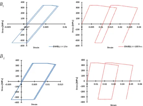
In order to have a complete overview of structure response to such cyclic loading conditions, cyclic load points B1 and B2 (Figure 3) are investigated and the corresponding stress strain responses at the steady state are presented
in Figure 7. For both dwell times, both points B1 and B2 show the plastic loading phase and creep ratchetting
behaviour due to the very large mechanical load. However point B2 has a higher strain levels due to the higher
temperature of 225ºC applied. When the dwell time is increased from 1 hour to 100 hours, creep strain is increased greatly for both load points, and more significant creep ratchetting mechanism is present.
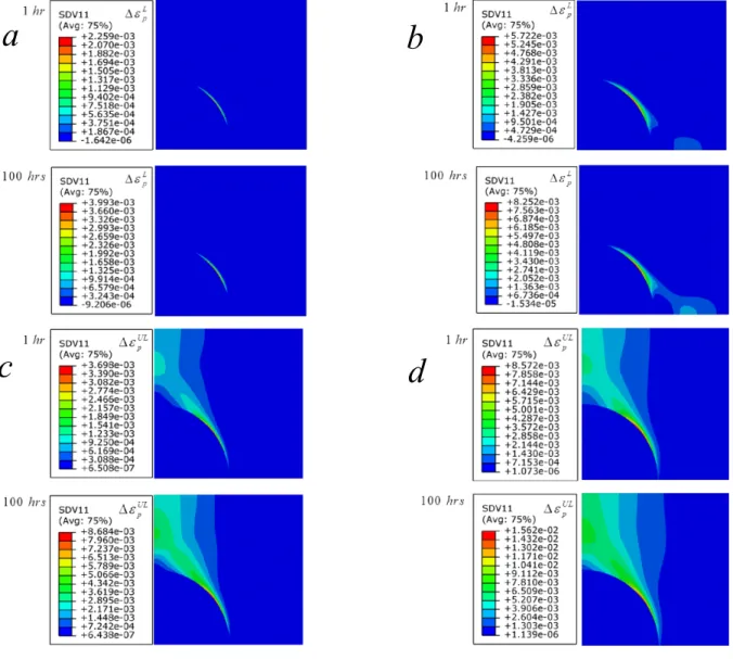
The detailed effects of different creep dwell times on plastic strains for both cyclic load points B1 and B2 are
reported in Figure 8. Figure 8a and Figure 8b show the plastic strain range during loading phase for point B1and B2
respectively, which involves a small and localized area in the “Interaction Boundary”. When the creep dwell time is increased the plastic region does not increase significantly and still highly localized, but with a greater plastic strain magnitude. For point B2 with higher temperature of 225ºC the plastic region becomes bigger and also slightly
increases for longer creep dwell. A similar trend is shown by Figure 8c and Figure 8d for cyclic load points B1 and
B2 respectively, where the plastic strain at unloading phase is reported. Both figures confirm the major plastic
damage occurs at the unloading phase, and involves a quite large area of matrix. The increase of both the dwell time and the thermal load enhances such behaviour significantly by dramatically increasing the plastic strain magnitude as shown in Figure 8c and Figure 8d. For both load points B1 and B2, the creep ratchetting behaviour becomes very
significant as it is enhanced by the high level of primary load. Dwell time is also crucial for the cell response to the cyclic load
Figure 7 Response of the steady state stress-strain path at location with the maximum plastic strain for different dwell time for load points B1
All the results confirm that creep ratchetting mechanisms is affected by two key parameters, dwell time and the primary load level. The analyses performed for cyclic load case A1 and A2 showed a closed hysteresis loop. The
increase of dwell time drastically changed the MMC response, introducing an evident creep strain accumulation even for such cases. In order to confirm the importance of the primary load on the creep ratchetting behavior, the
pure cyclic thermal load case is investigated, i.e.
0
0.0 1.0
P
y
.
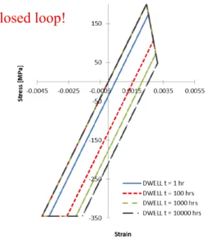
This loading condition is investigated by considering varying dwell times from 1 hour to a maximum of 10000 hours. The calculated hysteresis loops for different dwell times are shown in Figure 9. It is evident that when there is no primary load, despite the increase of creep dwell, the secondary thermal load is not capable of causing creep ratchetting in the MMCs. However, the increase of dwell time enhances the creep strain and the stress relaxation during the dwell period and consequentially enhances the plastic behavior during the unloading phase. This will inevitably increase the total strain range of the closed hysteresis loop, until a limiting state is reached, where all
a
b
d
c
thermal stresses are fully relaxed to zero, no further creep strain is induced, and hence there is no additional enhancement of reverse plasticity during the unloading phase. As presented in Figure 9, when there is no primary load, the creep strain occurred during the dwell period will be fully recovered by the plastic strain during the unloading phase, leading to a closed hysteresis loop.
In Figure 10 an overview of the stress fields at the end of creep and unloading phase for different dwell times is presented. Due to the material mismatch, at both loading phases the highest stress of matrix develops around the fibre, starting from the “Interaction Boundary”. When the creep dwell is increased, a significant stress relaxation occurs and the affected area becomes larger. Longer dwell time allows wider area to yield during the unloading phase, as shown in Figure 10. The increase of creep dwell also causes higher plastic strain during unloading, and such mechanism makes the size of the hysteresis loop larger.
Figure 10 Effect of dwell time on stress state at the end of creep and unloading phase respectively.
Figure 9 Response of the steady state stress-strain path at location with the maximum plastic strain for different dwell times.
4.2.Further studies on the effect of creep dwell on hysteresis loop and verification
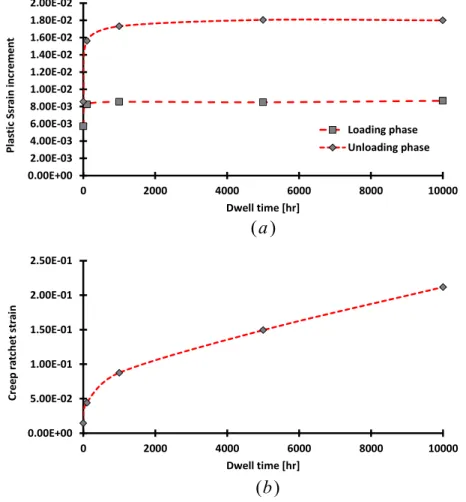
To further understand the effect of dwell time on the cyclic response of MMC, the plot of magnitudes of maximum plastic strain increments during loading and unloading phases against the applied dwell time is presented in Figure 11a, and the plot of maximum creep ratchet strain (i.e. the accumulated inelastic strain) per cycle against the applied dwell time is given in Figure 11b. It can be seen clearly from Figure 11a that when the applied dwell time is more than 1000 hours, the plastic strain magnitudes at both loading and unloading phases nearly keep unchanged. This behaviour occurs as the creep stress at the end of the dwell period reaches a steady state. By this point the creep stress cannot relax anymore and the plastic strain magnitude during the unloading phase cannot increase with the further increase of the dwell time. However it is observed from Figure 11b that the maximum creep ratchet strain almost increases linearly with the dwell time when the applied dwell time is more than 1000 hours. This highlights the effects of creep dwell time on both the shape of hysteresis loop, and the creep-fatigue life of the MMC. For a long dwell time, creep damage dominates and a creep ratchetting mechanism occurs. This highlights the importance of the dwell time for the life assessment of component operating under such loading conditions, even when the operated loading condition is below the shakedown limit.
( )
a
( )
b
0.00E+00 2.00E-03 4.00E-03 6.00E-03 8.00E-03 1.00E-02 1.20E-02 1.40E-02 1.60E-02 1.80E-02 2.00E-02
0 2000 4000 6000 8000 10000
P
la
st
ic
Ssr
ain
incr
e
m
e
n
t
Dwell time [hr]
Loading phase Unloading phase
0.00E+00 5.00E-02 1.00E-01 1.50E-01 2.00E-01 2.50E-01
0 2000 4000 6000 8000 10000
Cr
e
e
p
ra
tche
t
str
ai
n
Dwell time [hr]
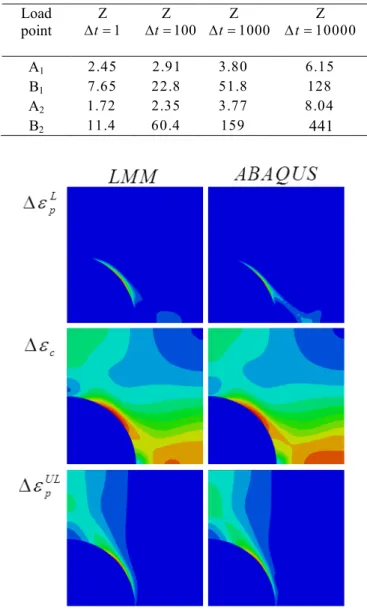
During the dwell period, both the stress relaxation and creep strain accumulation are observed for MMC. This is related to a phenomenon called elastic follow-up [2], and is typically quantified by an elastic follow up factor Z, defined by the ratio of the creep strain increment to the elastic strain increment during stress relaxation. Under constant displacement loading, the stress relaxation results in no change in the total strain, as creep strain replaces elastic strain with time, where Z=1. The elastic follow-up factor is known to be influenced by loading conditions [2, 6], and larger primary loads combined with longer dwell times produce larger Z. For the MMC investigated, the detailed elastic follow up factors at the location of maximum creep strain for different dwell times and 4 considered cyclic load conditions are presented in Table 3. This shows how the magnitude of the primary load affects the Z factor. When the MMC is subjected to a low mechanical load (A1 A2) only moderate increases occur when the dwell
time is increased, whereas radical changes are observed when the primary load is increased (B1 and B2).
Table 3 Values of elastic follow-up factor at location with maximum creep strain, for different loading conditions and creep dwell times.
Load point
Z
1 t
Z
100 t
Z
1000 t
Z
10000 t
A1 2.45 2.91 3.80 6.15
B1 7.65 22.8 51.8 128
A2 1.72 2.35 3.77 8.04
B2 11.4 60.4 159 441
In order to verify the LMM results a direct comparison with the ABAQUS step-by-step analyses is performed. Three quantities are considered in the verification procedure, the creep strain increment (
c), the plastic strain increment at loading ( Lp
) and the plastic strain increment at unloading ( UL p
). Direct comparisons of contours
and magnitudes of these plastic and creep strains obtained by the LMM and ABAQUS step-by-step analyses are given in Figure 12 and Table 4, respectively, and a perfect agreement is observed. It is evident that the LMM is capable of producing accurate solutions to estimate the cyclic response of MMC to the applied cyclic load condition with creep dwell. Furthermore, it is worth noting that the LMM creep fatigue analysis is much more efficient than the standard ABAQUS step-by-step analysis procedure. Based on a standard PC, the computational CPU cost to solve one cyclic loading case for any the dwell time required by the LMM analysis is approximately 149 seconds (150 total increments), against the 792 seconds (810 total increments) and 1268 seconds (2600 total increments) required by the ABAQUS step-by-step analysis for 1 hour and 10000 hours dwell times respectively. This comparison verifies the efficiency superiority of LMM.
4.3.Discussions on MMC damaging and response to the cyclic load
Among 6 cyclic loading points shown in Figure 3, the most critical one is B2. Hence for this loading point a
complete cell view is presented in Figure 13a and Figure 13b for the discussion. In previous sections it is well established that creep dwell time affects dramatically the structure response, due to the stress relaxation and redistribution, which are particularly damaging and responsible for the plasticity during the unloading and loading phase when the primary load level is high enough. Figure 13a shows the stress distribution at the end of the creep dwell for two cases, 1 hour and aluminium alloy metal matrix composite 1000 hours of dwell time. The associated residual stress during the creep dwell makes it possible to yield regions which normally don’t exhibit a plastic behaviour. This is highlighted by Figure 13b where the plastic strain increment at unloading phase is reported. Both the plastic strain magnitude and area at unloading phase largely increases by longer dwell times. Due to the transverse direction of the mechanical load, the reinforcement fibre does not improve the tensile strength of MMC significantly under such load condition, which is the most critical load condition the structure may experience. The most dangerous mechanism shows plasticity in both loading and unloading phase. In such condition creep and creep ratchetting become extremely damaging when the dwell time increases.
Table 4 Comparison between LMM and Step-by-Step Abaqus analyses, for different cyclic loading points.
L p
c
ULpCyclic load point LMM ABAQUS LMM ABAQUS LMM ABAQUS
A1 0 .0 0 .0 2.21E4 2.53E4 1.80E4 2.00E4
B1 2.26E3 2.01E3 1.76E3 1.74E3 3.70E3 3.51E3
A2 0 .0 0 .0 1.20E3 1.25E3 1.13E3 1.20E3
The effect of dwell time on the strain evolution is presented in Figure 14, where the plastic and creep strains contours are shown for different dwell times. The loading phase is not affected by the increase of the dwell duration, because it starts after the tensile peak. Instead the unloading phase is remarkably enhanced by the increase of the creep dwell, which increases the stress drop at the most critical location, and enhances the reverse plasticity by increasing the total strain range. Furthermore, the creep strain increases remarkably over the different dwells analysed. For this particularly dangerous cyclic loading condition (B2), the matrix experiences a large stress
redistribution during the creep dwell and also a high level of stress during both the creep and unloading phase (Figure 15). Such a high level of stress makes the creep damage dominant for dwell times up to 1000 hours. Instead for dwell time up to 10000 hours classical monotonic creep rupture occurs. The creep rupture failure initiates always in the interface area but rapidly involves the entire surrounding matrix. Then it is not capable of withstanding the applied load condition, and a fast increase of the creep strain is expected due to the increasing creep damage. It is important to underline that these failure analyses are performed within the shakedown limit. Without the presence of the creep dwell none of the aforementioned failure mechanisms can be observed.
Figure 13 a)Effect of dwell time on the stress distribution for the complete unit cell at the end of creep dwell, for cyclic load point B2, b)Effect
of dwell time on the plastic strain increment of the complete unit cell during unloading phase, for cyclic load point B2
1
hr
100
hrs
1000
hrs
10000
hrs
Plas
ti
c
s
tr
ain
a
t
loa
ding
C
re
e
p
Str
ain
Plas
tic
str
ain
at
un
lo
ad
in
g
Figure 14 Strain contours at loading, creep and unloading for a uniform cycling temperature θ0 = 225 °C and a constant mechanical load σp =
241.5 MPa for different dwell times.
1
hr
100
hrs
1000
hrs
10000
hrs
M
is
e
s
str
ess
at
end
o
f
cr
ee
p
d
w
ell
M
is
e
s
st
res
s
at
unl
oad
in
g
Figure 15 Stress contours at end of the creep dwell and unloading phase for a uniform cycling temperature θ0 = 225 °C and a constant mechanical
4.4.Creep Ratchetting failure in the MMCs
Creep ratchetting is a dangerous mechanism, which can interact with creep and fatigue and it may become dominant. Figure 16 shows the creep ratchetting interaction diagram, which is useful to understand the response of the microstructure. The creep strain and net plastic strain, which is the difference between the plastic strain at loading and unloading phase, are displayed on the vertical and horizontal axes respectively. Closed loop is possible only if the creep strain is fully recovered by the net plastic strain. However this closed loop condition is remarkably affected by both the dwell time and the stress relaxation. The closed loop limit can be represented by a 45 degree slope line as shown in Figure 16. The cyclic loading points A1, B1, C1 are investigated for increasing dwell times.
Only for short hold period, a closed loop is possible especially for high mechanical load level (up to 1 hour). Otherwise the results diverge on the upper part of the limit (Figure 16). This means that the creep-ratcheting mechanism is creep strain dominated.
0.000 0.005 0.010 0.015 0.020 0.025 0.030 0.035 0.040
0 0.005 0.01 0.015 0.02 0.025 0.03 0.035 0.04
Cr
ee
p
St
ra
in
Net Plastic Strain
Closed Loop Limit C1
B1
A1
Figure 16 Creep ratchetting interaction diagram for different cyclic loading points (Error! Reference source not found.) at increasing creep dwells
If the saturated cycle is an open loop, the number of cycle to failure due to the creep ratcheting can be evaluated using the simple strain ductility exhaustion equation [22], which is characterized by the ratio between the tensile strain to fail and the calculated ratchet strain per cycle. The creep ratchetting strains per cycle at two temperature conditions are shown in Figure 17 for different mechanical loads. For both temperature conditions, it is shown that no ratchetting mechanism occurs when the mechanical load is zero, and the increase of such ratchetting strain per cycle has the same dependency on the applied mechanical load.
0.00% 0.10% 0.20% 0.30% 0.40% 0.50% 0.60% 0.70% 0.80%
0 0.1 0.2 0.3 0.4 0.5
C reep Ra tche ttin g Str ai n P er Cy cle
Normalised transverse mechanical load
Dwell time = 1 hr Dwell time = 100 hrs Dwell time = 1000 hrs
0.00% 0.20% 0.40% 0.60% 0.80% 1.00% 1.20% 1.40% 1.60%
0 0.1 0.2 0.3 0.4 0.5
C reep Ra tche ttin g Str ai n P er Cy cle
Normalised transverse mechanical load
Dwell time = 1 hr Dwell time = 100 hrs Dwell time = 1000 hrs
150
C
175
C
Figure 17 Creep Ratchetting Strain per cycle at 150 and 175 °C for different transverse constant mechanical load, normalised by the yield of the matrix.
The effect of temperature on the creep ratchetting strain per cycle has also been shown in Figure 17 against the normalised transverse mechanical load. For a normalised mechanical load of 0.5 the ratchetting strain per cycle increases from 0.7% to 1.4% for the 1000 hours dwell time when the temperature increases from 150 and 175 °C. Despite this it has been observed that the creep damage becomes dominant for longer dwell time and high mechanical load, and it is enhanced by higher temperatures.
UL p
r
1 10 100 1000 10000 1 10 100 1000 10000
1 10 100 1000 10000
Ncr Ncf
Dewll time [hrs]
Ncf Ncr
)
a
)
b
Figure 18 a) Creep-fatigue life and creep ratchetting life against dwell time, b) contours of the plastic strain at unloading phase and the creep-ratchetting strain per cycle for a cyclic temperature of 150 °C and a constant mechanical load 0.25 time the yield of the matrix.
of 150 °C. Up to 1000 hours, creep-fatigue life (Ncf) is almost independent on dwell time and the fatigue damage
dominates due to the low temperature of 150 °C considered, making the creep damage negligible. For dwell times longer than 1000 hours creep damage becomes significant, and competes with the damage caused by fatigue. The number of cycles to failure calculated using a strain ductility (Ncr) approach are higher than the number of cycles to
failure due to creep-fatigue interaction (Ncf) for dwell time up to 10 hours. After this threshold of 10 hours creep
ratchetting becomes dominant and causes the failure rather than the creep-fatigue interaction. In such a case the damage is associated with a large change in the size of cross-section area due to the material necking. A proof of this creep ratchetting mechanism is shown in the contours presented in Figure 18b, where both the plastic strain at the unloading phase (left) and the ratchet strain increment per cycle (right) are presented. The magnitude of ratchet strain shown in Figure 18b is larger than the plastic strain that occurs during the most dangerous cyclic phase. This means that the damage caused by the creep ratchetting is more significant than the damage produced by creep and fatigue interaction. In Figure 19a, the creep-fatigue life and creep ratchetting life are reported against the dwell time for a temperature of 175 °C. For all the dwell times studied creep ratchetting is always less damaging than the combined damage due to fatigue and creep. For such a cyclic loading condition the driving fatigue and creep failure mechanism is the creep-fatigue interaction for intermediate dwell (up to 100 hours) and creep dominated for longer dwell periods (larger than 1000 hours). Figure 19b presents the contours of the plastic strain at the unloading phase and the creep ratchetting strain increment per cycle. For this loading case the two quantities are comparable, but the damage caused by the creep ratchetting strain per cycle is still negligible respect to that caused by combined damage due to the creep and fatigue interaction.
1 10 100 1000 10000
1 10 100 1000 10000
1 10 100 1000 10000
Ncr Ncf
Dewll time [hrs]
Ncf Ncr
)
a
)
b
UL p
r
5.Conclusions
The work presented in this paper investigates the interactions between fatigue and creep damages of a fibre reinforced MMC subjected to a cyclic temperature and constant mechanical load by using the LMM extended DSCA with micromechanical modelling. The MMC is modelled using an idealised plain strain model, where both matrix and fibre materials are modelled as elastic-perfectly plastic. The time dependant creep behaviour is modelled using the Norton-Bailey relationship.
A detailed study on MMC responses to different cyclic load points within the shakedown limit is performed. The primary load level and dwell time are confirmed to be the two most important parameters for creep-fatigue interaction. When the dwell time is small enough (e.g. 1 hour) a closed hysteresis loop can be observed for a low level of primary load. Conversely when dwell time increases creep ratchetting become significant. The increasing dwell time increases the total strain range, by increasing the plastic strain increment during unloading phase, due to the stress relaxation during the creep dwell period. Once the steady state creep stress is reached at the end of the creep dwell no more increase of plastic strain increment is possible. Typically for a long dwell time (more than 1000 hours), creep ratchetting is present with an inelastic strain accumulation at each cycle, the magnitude of which increases almost linearly with the dwell time. When the primary load is zero, creep ratchetting does not take place for any thermal load level and dwell times.
In addition to these results, a discussion on the failure mechanisms is presented for the most critical cyclic load point (B2), presenting a full unit cell view. The main contribution to the MMC damaging is the stress relaxation and
redistribution during the dwell period, which makes it possible to yield regions which normally don’t exhibit a plastic behaviour without the creep dwell. Overall, the life and integrity of MMC is reduced by the combined action of creep and fatigue damages, as well as the accumulated inelastic strain per cycle due to the creep ratchetting mechanism. At this high level of mechanical load, dwell time has a strong impact on the failure mechanism. For dwell times up to 1000 hours, the creep fatigue failure is dominated by creep damage. Otherwise for extremely long dwell times (up to 10000 hours), the monotonic creep rupture occurs.
The effect of temperature on creep ratchetting is also investigated, and it has been demonstrated that for a low temperature of 150 °C, creep ratchetting is dominant over the creep-fatigue interaction after a critical dwell period when a mechanical load is applied. Conversely at a higher temperature of 175 °C, the damage caused by creep ratchetting is less significant than the damage caused by creep fatigue interaction, where creep and fatigue damages are comparable for dwell times between 1 and 100 hours. However at such a higher temperature condition, when the dwell period is beyond 100 hours, creep damage dominates.
The accuracy and efficiency of the LMM extended DSCA for the evaluation of cyclic plastic creep behaviour of MMC has been confirmed by direct comparisons with a set of ABAQUS step-by-step analyses. All the comparisons demonstrate that LMM is capable of providing accurate solutions, with reduced computational efforts.
Acknowledgements
References
[1] Manson, S., and Halford, G. R., 2009, Fatigue and durability of metals at high temperatures, ASM International. [2] Ainsworth, R., 2003, "R5: Assessment procedure for the high temperature response of structures," British Energy Generation Ltd, 3.
[3] American Society of Mechanical Engineers, B., and Pressure Vessel, C., 2007, ASME boiler & pressure vessel code : an international code, New York, N.Y. : American Society of Mechanical Engineers.
[4] Chen, H., Chen, W., and Ure, J., 2014, "A Direct Method on the Evaluation of Cyclic Steady State of Structures With Creep Effect," Journal of Pressure Vessel Technology, 136(6), pp. 061404-061404.
[5] Chen, H., and Ponter, A. R., 2006, "Linear Matching Method on the evaluation of plastic and creep behaviours for bodies subjected to cyclic thermal and mechanical loading," International Journal for Numerical Methods in Engineering, 68(1), pp. 13-32.
[6] Bree, J., 1968, "Incremental growth due to creep and plastic yielding of thin tubes subjected to internal pressure and cyclic thermal stresses," The Journal of Strain Analysis for Engineering Design, 3(2), pp. 122-127.
[7] Fleming, W. J., and Temis, J. M., 2002, "Numerical simulation of cyclic plasticity and damage of an aluminium metal matrix composite with particulate SiC inclusions," International Journal of Fatigue, 24(10), pp. 1079-1088. [8] Qing, H., 2013, "Automatic generation of 2D micromechanical finite element model of silicon– carbide/aluminum metal matrix composites: Effects of the boundary conditions," Materials & Design, 44(0), pp. 446-453.
[9] Qing, H., 2013, "2D micromechanical analysis of SiC/Al metal matrix composites under tensile, shear and combined tensile/shear loads," Materials & Design, 51(0), pp. 438-447.
[10] Echle, R., and Voyiadjis, G. Z., 1999, "Simulation of damage evolution in a uni-directional titanium matrix composite subjected to high cycle fatigue," International Journal of Fatigue, 21(9), pp. 909-923.
[11] Schneider, Y., Soppa, E., Kohler, C., Mokso, R., and Roos, E., 2011, "Numerical and experimental investigations of the global and local behaviour of an Al(6061)/Al2O3 metal matrix composite under low cycle fatigue," Procedia Engineering, 10(0), pp. 1515-1520.
[12] Yuan, M. N., Yang, Y. Q., Li, C., Heng, P. Y., and Li, L. Z., 2012, "Numerical analysis of the stress–strain distributions in the particle reinforced metal matrix composite SiC/6064Al," Materials & Design, 38(0), pp. 1-6. [13] Guo, S., Kang, G., and Zhang, J., 2011, "Meso-mechanical constitutive model for ratchetting of particle-reinforced metal matrix composites," International Journal of Plasticity, 27(12), pp. 1896-1915.
[14] Baxevanis, T., and Charalambakis, N., 2010, "A micromechanically based model for damage-enhanced creep-rupture in continuous fiber-reinforced ceramic matrix composites," Mechanics of Materials, 42(5), pp. 570-580. [15] Pandorf, R., and Broeckmann, C., 1998, "Numerical simulation of matrix damage in aluminium based metal matrix composites," Computational Materials Science, 13(1–3), pp. 103-107.
[16] Chen, H., and Giugliano, D., 2015, "On the behaviour of fibre reinforce metal matrix composites under loading and thermal cycling conditions," 20th International Conference on Composite MaterialsCopenhagen.
[17] Chen, H. F., and Ponter, A. R. S., 2005, "On the behaviour of a particulate metal matrix composite subjected to cyclic temperature and constant stress," Computational Materials Science, 34(4), pp. 425-441.
[18] Gorash, Y., and Chen, H., 2013, "Creep-fatigue life assessment of cruciform weldments using the linear matching method," International Journal of Pressure Vessels and Piping, 104(0), pp. 1-13.
[19] Gorash, Y., and Chen, H., 2013, "On creep-fatigue endurance of TIG-dressed weldments using the linear matching method," Engineering Failure Analysis, 34(0), pp. 308-323.
[20] Gorash, Y., and Chen, H., 2013, "A parametric study on creep-fatigue endurance of welded joints," Proceedings in Applied Mathematics and Mechanics, 13(1), pp. 73-74.
[21] Maximov, J. T., Duncheva, G. V., Anchev, A. P., and Ichkova, M. D., 2014, "Modeling of strain hardening and creep behaviour of 2024T3 aluminium alloy at room and high temperatures," Computational Materials Science, 83(0), pp. 381-393.