Configurational optimizer of Combined Cycle
Propulsion using Genetic Programming
Alessandro Mogavero
Department of Mechanical and Aerospace engineering University of Strathclyde
Glasgow, UK G1 1XJ
Email: [email protected]
Abstract—In most engineering applications the optimization is employed after the conceptual design is already frozen with the only purpose of perfecting it. Although optimization algorithms capable of optimizing the configuration exist, their application is limited to electronics or control design, while for complex systems the conceptual design is often performed with manual trade off analyses among few options.
In hypersonic propulsion for instance, the choice of which flow cycle to use is made mainly by means of experience or in the best case by a trade off between radically different architectures. For Combined Cycle Propulsion (CCP) however many flow cycle possibilities are available and it is very possible that the final design is influenced by the preconceptions of the engineers rather than a pure objective judgement. Therefore a configurational optimization process, not bound to any known configuration, can potentially deliver totally new engine concepts, aiding the creativity of the designer.
In this paper the first steps toward a configurational op-timization of CCP are shown. This opop-timization is intended to find the optimal engine design without knowing the engine conceptual design a-priori. The optimization algorithm is based on the Genetic Programming (GP) and it was presented for the first time at the 20th AIAA International Space Planes and Hypersonic Systems and Technologies Conference. In the present paper the fitness function has been improved with the addition of a constraint like penalty function designed to solve a convergence problem outlined in the previous version.
The results presented in this paper demonstrate that the optimizer is able to converge to a reasonable configuration, coher-ent with the engineering practice. Moreover the improvemcoher-ents proposed in this paper proved to be effective in the mitigation of the previously detected problem, thus demonstrating that the optimization algorithm is robust and that the previous problems were only due to a poorly defined fitness function.
I. INTRODUCTION
Design optimization is becoming a common practice in engineering, mainly thanks to the advance of computer tech-nology. The capability of executing complex calculations in a very short time has enabled the usage of Computer Aided Engineering (CAE) not only as a verification tool when the design is frozen, but also as a decision making tool. CAE analyses are used from simple trade off studies based on a single aspect of the design, to complex Multi-disciplinary Design Optimization (MDO) that systematically choose the optimum solution considering many different aspects of the problem simultaneously.
In contrast with other industrial fields, such as aviation propulsion for instance, hypersonic propulsion is a very
in-novative field with no well established standards. In aviation propulsion the fundamental engine design is well established. The type of engine is selected depending on the application, for example bypass turbojet is used for transonic airliner, turboprop and piston engine for slower and smaller aircraft. Moreover the industries have accumulated knowledge over time, so they do not really need to design an engine from scratch, but they rather proceed by refinements of previous engines. In hypersonics a flying prototype does not exist yet, therefore the debate on which will be the best engine in these conditions is far from over (see [1]–[4]). Moreover, the possible engine configurations proposed for this application are diverse, and almost every time a new program is attempted a new concept is proposed.
For this reason in this research we propose a configura-tional optimization intended to find the optimal engine design without knowing the engine conceptual design a-priori. Such an optimizer has the potential to perform trade-off analyses minimizing the input required by the designer and therefore minimizing the possibilities that the design could be affected by his/her preconceptions. Moreover the optimization process, not bound to any known configuration, can potentially deliver totally new engine concepts.
Many examples of propulsion system optimization are present in the recent literature. Jahingir et al. in [5] and Pastrone et al. in [6] for instance performed optimization of a Rocket-Based Combined Cycle (RBCC) engine using evolu-tionary techniques, while in [7] an example of optimization of Turbine-Based Combined Cycle (TBCC) engine can be found. In [8] an example of optimization of a single part of an engine, the geometry of the ejector, can also be found.
Often in hypersonic propulsion, especially when applied to space access vehicles, the engine optimization is performed at the same time as vehicle optimization. Bayley et al. in [9] for instance performed a full vehicle optimization of a classical solid propellant rocket. While more recently Gong et al. in [10] completed a full vehicle and trajectory optimization of a suborbital vehicle powered by an RBCC engine. In this case the full potential of cutting edge High Performance Computing (HPC) is exploited to include into the optimization also high fidelity tip to tail Computational Fluid Dynamic (CFD) analyses of the vehicle.
In all the previous examples however, the engine conceptual
© © 2016 IEEE. Personal use of this material is permitted.
Permission from IEEE must be obtained for all other uses, in any current or future media, including reprinting/republishing this material for advertising or promotional purposes, creating new collective works, for resale or
configuration is defined and fixed, while the optimizer can change the design by tweaking a set of parameters.
An attempt to automatically select the best conceptual engine design is given by Steele in his PhD work [11]. In [11] a pool of predefined engine configurations is considered and then the optimizer acts on the number of engines installed aboard, their type and the sequence in which they are used. In his literature review Steele also noticed that other attempts to do that have been only trade-off analyses between different solutions. Brock et al. in [12] performed several studies for a Two Stage to Orbit (TSTO) vehicle considering different propulsion solutions, such as RBCC, TBCC and simple rock-ets, in order to determine which one would have been the best choice. In [13] similarly to [11] the study considered first a pool of different engine types and then the performance of the space access vehicle was evaluated changing the combination of engine type, the sequence of their usage, the fuel option and also the possibility to take off horizontally or vertically. In all these studies however the configuration of the propulsion system had to be defined a-priori, the optimization procedure (where present) was only able to choose between a pool of engines with fixed design.
In this paper instead the updates of a novel engine op-timization procedure are described, the engine conceptual configuration does not need to be defined a-priori, but it is the actual result of the optimization process. The modularity and flexibility of a previously developed engine model, called HYbrid PRopulsion Optimizer (HyPro) (see [14], [15] and section II), is employed here by a configurational optimizer to create randomly generated engine configurations later op-timized by means of an Evolutionary Algorithm (EA). The scope of the optimizer is therefore to define how the HyPro modules are interconnected, thus potentially being able not only to choose between TBCC or RBCC (as done in previously cited examples) but also to propose new engine concepts.
In contrast with the examples of engine optimization cited above, in this study the optimization has only been performed at a single operative point, since the optimizer is not mature enough to be used for a full mission optimization. The opti-mization at a single point is however considered by the author an important milestone to be developed before attempting a full mission study.
The optimization algorithm described in this paper was pre-sented for the first time at the 20th AIAA International Space
Planes and Hypersonic Systems and Technologies Conference in [16]. In this paper the aforementioned algorithm is improved with respect to that presented in [16] with the addition of a constraint like penalty function (see section III-B) designed to solve one of the problems encountered in [16].
II. PROPULSION MODEL
In this work an in house developed tool for propulsion sys-tem analysis, dubbed HYbrid PRopulsion Optimizer (HyPro) has been employed for the evaluation of the fitness function. The propulsion model has been specifically designed to be included in the optimization loop described in this paper. The
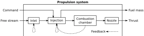
Inlet Injection Combustion
chamber Nozzle
Free stream Thrust
Command Fuel mass
Propulsion system
[image:2.612.311.564.49.112.2]Feedback
Fig. 1. Example of the modular structure of the propulsion model for a Scramjet/Ramjet.
model is targeted especially toward the analysis of combined cycle configurations such as TBCC or RBCC (see [14], [15]). The model is designed to be flexible enough however to model almost any possible engine configuration, from a simple rocket or ramjet to an almost arbitrary combination of propulsive components.
The HyPro software is written in C++, and has a structure that takes advantage of the intrinsic modularity of the object oriented programming paradigm that is embodied within this programming language (see [17]). This modularity brings an innate flexibility to the software and allows it to be configured easily to model many different kinds of propulsion systems. Moreover, thanks to the object oriented structure of the software, it is possible to implement every module in terms of a defined set of properties and parameters that can be changed easily at any time during the execution of the model. Indeed, every engine component is characterised in terms of a dedicated C++ class and each component can be connected to any other in any possible pattern. Using advanced C++ features such as inheritance and template classes, different physical models can be combined easily to generate more complex modelling without the need to develop dedicated C++ classes. This maximizes the code re-utilization, facilitates the code readability and maintainability and improves the flexibility of the software. For all the aforementioned reasons, HyPro is particularly well-suited to be used within optimization studies and also as a sub-model within a more comprehensive computational representation of the entire vehicle system (see [18]).
The modules are connected between each other by means of nodes, each node contains a set of physical quantities that are then actually shared by contiguous modules. A node represents the thermo-kinetic state at a certain station within the engine, thus it contains all the information required to define the thermodynamic state (for example the composition, pressure and temperature for a mixture of ideal gases), the speed of the flow and the area of the section.
Every module does not see directly the other modules it is connected to, but it only stores a pointer to the nodes connected to it, that in turn are connected with other modules. Each module is connected to at least two nodes, an input node hereafter calledN1 and an output node calledN2.
Inlet Injection Combustion chamber Nozzle
Free stream Thrust
Fuel mass
Propulsion system
Mixer Rocket Command
[image:3.612.52.301.49.133.2]Feedback
Fig. 2. Example of the modular structure of the propulsion model for a RBCC engine.
be modelled by collating and interconnecting all the required modules, then switching on/off certain modules according to a pre-defined schedule of operation. In Fig. 2 an example of the model configured to represent a RBCC propulsion system is illustrated.
In HyPro the flow within the engine is solved module by module iteratively. Usually the calculation proceeds from upstream to downstream, but when choking phenomena occurs within the system then information has to be propagated in the opposite direction to let the upstream flow path adapt to its presence. In this case a ‘choking feedback’ needs to be defined a-priori in order to properly handle the required iterative procedure (see dashed lines in Fig. 1 and Fig. 2).
III. CONFIGURATIONAL OPTIMIZATION
The problem of optimising the structural layout or config-uration of an engine can be handled very efficiently using Genetic Programming (GP) [19]–[21].
GP has indeed been applied successfully to various engi-neering problems, where the structure of the design needed to be optimized. In many of these cases, similarly to HyPro (see section II), a block diagram approach is used to model the physics of the problem and its structure is then optimized with GP. Examples of this approach can be found for dy-namical systems [22], [23], control systems development [24], electronic circuit design [25] and also to various problems in aerospace engineering such as the design of an antenna for the NASA Space Technology 5 spacecraft [26], [27].
GP has been selected for this application, due to the simi-larity with all the aforementioned application examples. Other completely different approaches to solve the same problem might be however possible. A direct comparison against GP is at the moment not possible due to the absence in literature of any other attempt to perform configurational optimization of this kind of engines.
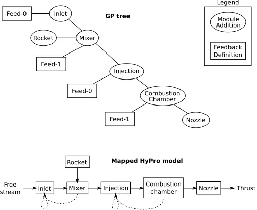
A. Cellular encoding
In the case of the aforementioned antenna optimization the correspondence between GP tree and the antenna structure is clear, because the shape of the antenna is also a tree. Other design models such as an electric circuit, a control system with feedbacks and also the flow structure of an engine, cannot be sketched as a tree. Despite this difficulty also these problems can be optimized using GP with the addition of a computational step, called genotype to phenotype decoding
Inlet Injection Combustion
chamber Nozzle Free
stream Mixer Thrust
Rocket Feed-0 Inlet
Injection
Combustion Chamber
Nozzle Feed-0
Feed-1 Mixer
Rocket
Feed-1
Module Addition
Feedback De nition Legend
GP tree
Mapped HyPro model
Fig. 3. Mapping between an example GP tree chromosome (top) and its corresponding HyPro engine model (bottom).
[20], to map the physical model starting from the GP tree (see for instance [22]–[25]).
Due to the similarities between the engine flow network of HyPro and an electrical circuit scheme, the approach used by Koza in [25] to optimise the layout of electronic circuits is most appropriate for this application, but some modifications to account for certain specifics of the engine modelling prob-lem need first to be accounted for. As anticipated above, not all engine configurations can be represented directly in terms of a tree-shaped chromosome. This is particularly the case when the possibility of feedback between the modules that comprise the engine must be accommodated in the HyPro model. To obviate this problem, Koza introduced a method calledcellular encoding [20], in which the GP genes represent a list of instructions that modify an initial simple prototype structure for the individual [20], [25], rather than representing directly the structure of the individual itself. In the automated design of a complex electronic circuit many different instruction gene types need to be coded for (for instance the addition of parallel components, serial components, and so on), in this work only two types of operation are defined: the addition of one specified HyPro module, and the addition of feedback between two specified modules.
[image:3.612.312.564.51.257.2]addition’ gene has also one ‘feedback definition’ gene as a child.
The ‘feedback definition’ gene’s value is an integer, that de-fines the feedback destination, the value indicates the number of modules to be counted upstream of the feedback source. In Fig. 3 for instance, the ‘feedback definition’ gene ‘Feed-1’ (i.e. with value equal to 1) child of the gene ‘Combustion Chamber’ defines a feedback from the ‘Combustion Chamber’ module to the ‘Injection’ module, that is placed one position upstream. The gene ‘Feed-0’ instead defines a feedback loop with the same source and destination, since the destination is zero positions upstream of the source. In the case that the ‘feedback definition’ value would set the destination past the most upstream module, the latter is assumed as feedback destination. The aforementioned counting strategy however, is not unequivocal in the cases where the engine flow path is a branching structure (i.e. there is at least a ‘Mixer’ module). In Fig. 3 for instance, when counting past the ‘Mixer’ module, it is not clear if the module upstream the ‘Mixer’ is the ‘Inlet’ or the ‘Rocket’. This problem is solved introducing an iterator that counts by branches, such an iterator moves only on the branch linked to the node N1 of the ‘Mixer’ and then, once
the most upstream module of that branch is reached, it moves on the other branch starting from the module connected with nodeN3(in the ‘Mixer’ moduleN1andN3are the input nodes
whileN2 is the output node as for any other module). That is
why in Fig. 3 the gene ‘Feed-1’ child of the ‘Mixer’ defines a feedback pointing to the ‘Inlet’ and not to the ‘Rocket’, because the former is linked to the node N1 of the ‘Mixer’.
In the end it is worth noticing that the ‘feedback definition’ gene requires no child, therefore it is always a terminal.
The aforementioned GP formalism is implemented in HyPro using the Genetic Programming C++ Class Library (GPC++) that is based upon the work of Koza [20], [21], [28]. The library has been integrated into HyPro after some modification to allow strongly typed GP of the form described above.
B. Fitness function
In [15], [16] the fitness function chosen was the specific impulse of the engine. This choice represents the simplest possible optimization for an engine, because it does not take into account many other requirements such as the specific thrust for example. In detail the fitness function ft is defined as follow:
ft=
g0m˙f
F , if calculation is correct
∞, if exception is thrown or F <0
(1)
whereg0is the gravitational acceleration at sea level,m˙fis the
mass flow rate of propellant consumed andF is the net thrust. In case the calculation performed in HyPro is not successful an exception is thrown and the fitness is assumed infinite. The handling of exceptions during the fitness evaluation is important because during the evolution is possible to generate individuals that cannot actually be run in a stable manner to produce thrust. These non-viable engines however are not
discarded out-of-hand from the population, since they might merely correspond to an intermediate stage in the evolution of an engine configuration that might prove very successful in later generations.
In this work the fitness definition has been improved with respect to the previous calculations (see [15], [16]) in order to make more realistic the optimization process (see section IV for more details). Beside the specific impulse a parameter linked with the size of the engine has been added, leading to the following formulation:
ft= (
ft, if Ain≤Amax
ft+KAin, if Ain> Amax
(2)
where Ain is the cross section area of the engine’s
air-breathing intake and K is a constant big enough to guarantee
KAinft. Eq. 2 is designed to behave as a constraint penalty
function on the maximum size of the engine (i.e. Amax in
Eq. 2).
C. Algorithm initialization
In order to start the evolution the GP search space need to be defined. The search space consists of a pool of genes that will be used to randomly generate the population at generation zero and to randomly generate sub-trees during the mutation operation. The pool of ‘feedback definition’ genes simply consists of a gene for each integer number between zero and a sufficient high value chosen by the user. The pool of ‘module addition’ genes consists instead of a gene for each propulsive module, which the user wants to consider in the optimization. The parameters of a module cannot be changed by the GP optimizer, which acts only on the interconnection between modules present in the pool.
IV. RESULTS
In [15], [16] two test cases were analysed to verify this optimization algorithm, one in supersonic engine operative conditions and the other in subsonic. In subsonic conditions the optimization algorithm was not able to converge to a solution supposedly due to the absence of any size constraint, leading to unrealistic engine configurations. In this section the results obtained with the new constrained fitness function, defined in section III-B, are compared with the previous one showing a clear improvement and the resolution of the aforementioned issue.
The initial pool of ‘module addition’ genes (see section III) has been constructed starting from the modules used to rep-resent a typical RBCC engine (see [14]–[16] for details). The list of modules considered comprises: an inlet, an ejector mixer, a fuel injection module, a combustion chamber, a rocket injection module, a nozzle and a simple duct (see [14], [15] for detailed description of each module).
The fitness function described in Eq. 2 has been calculated considering a maximum cross section area of Amax = 3m2
andK= 100 1
sm2.
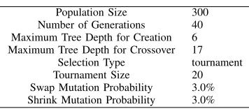
TABLE I
PARAMETERS FOR THEGP ALGORITHM[21].
Population Size 300
Number of Generations 40 Maximum Tree Depth for Creation 6 Maximum Tree Depth for Crossover 17
Selection Type tournament
Tournament Size 20
Swap Mutation Probability 3.0% Shrink Mutation Probability 3.0%
subsequent generations. A maximum depth for the tree struc-ture of the chromosome of each individual was imposed simply in order to limit the complexity of the configurations that might emerge through evolution from the initial population. The probability of mutation in the examples presented here was kept non-zero but small in order to increase the diversity of the population.
The optimised configuration that emerges in subsonic oper-ational conditions (Mach 0.5) at sea level (temperature 288.15 K and pressure 101.325 kPa) is shown in Fig. 5, where the feedback loops have been removed for clarity. With a little bit of puzzling it is apparent that, in its essence, the configuration is that of an ejector ramjet, albeit with multiple inlets and a very complex internal flow path.
As was demonstrated in [15], [16], the algorithm has introduced additional complexity into the engine configuration in order to accommodate the inherent deficiencies in the modelling procedure, namely the inability of the optimizer to tune directly the parameters of the engine’s modules. In this case the various additional inlets seem to have been introduced as a way of augmenting the flow of air trough the secondary; the human designer would have achieved the same end simply by increasing the size of a single inlet.
In Fig. 7 the evolution of the fitness of this new test case is compared against the old unconstrained test showed in [15], [16]. It is evident that, while with the previous case the evolution has not converged to a definitive solution, in the new test case the fitness reaches a plateau at about generation 5 separating drastically from the previous curve.
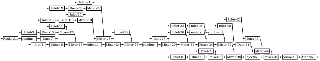
The reason why an optimum solution is not possible without a constraint, is that, in the frame of the mathematical model used in HyPro for the Ejector RamJet (ERJ), the greater the secondary flow (i.e. the air flow through the inlets) is compared with the primary (i.e. the rocket exhaust) the greater is the performance of the engine. Without a constraint the amount of inlets (i.e. the size of the engine) increases iteration after iteration, leading to a very complex configuration at generation 20 (see Fig. 4) and to a configuration at generation 40 so complex that it is actually impossible to show here. This behaviour is after all physically reasonable if we assume that the mixing is always possible no matter how much the secondary flow is bigger than the primary, indeed the propulsive efficiency of an air-breathing engine increases if the mass of air used increases. This design optimization process resembles the design trend in turbofan engines to progressively
0 5 10 15 20 25 30 35 40
10−4 10−3
Generation #
Fitness [1/s]
Fitness with cross section constraint
[image:5.612.85.263.75.153.2]Fitness without constraints
Fig. 7. Optimization results. Evolution of fitness of the best individual. Comparison between old results obtained with an unconstrained fitness and new results obtained with the max cross section area constraint.
increase the bypass ratio. In order to obtain practical results, the addition of other considerations beside the pure engine performances are therefore required and here a first attempt, consisting in the addition of a constraint on the engine size, has demonstrated to be effective.
If compared against an existing engine concept, the results of this optimization loop perform much better. The Hyperion engine studied by Olds in [29] for instance has a specific impulse of 400s at Mach 0.5, that translates into a fitness function of0.0025accordingly with Eq. 2. Even if this demon-strate that the optimized configuration performs better than the engineering practice, the results here presented must be taken with caution, since the complex multi-inlet configuration of Fig. 5 might be impractical for many other points of view.
The optimization with this new fitness has been run several times in order to have an assessment of the repeatability. In Fig. 7 it can be noted that, even if the convergence history is different, all the runs converge to very similar values of fitness. In Fig. 5 and Fig. 6 the configuration of the best individual at the last generation is depicted for two test repetitions. Even if the two structures represent an ejector ramjet in both cases, they are sensitively different. The fact that their fitness is almost equal however, demonstrate they the two different configurations are equivalent in the frame of this analysis, thus it can be stated that the optimizer converged to two equally performing optimums.
especially during the first generations, where the GP is still far from the final solution, some very complex engine models might be evaluated. The computational complexity of a single engine model can be assumed proportional to the total number of the modules that comprise the engine. This assumption is however strictly true only in case no feedback iteration has to be performed, so generally a certain computational overhead has to be accounted any time a feedback loop is present. A clear dependency on the total number of feedback loops is however impossible to outline, since the actual complexity of the loop depends on many factors. In any case, given the very low time cost of this first test case, it is possible to speculate with a fair degree of confidence that a full optimization will be still possible with the addition of more modules and more complicated engines.
V. CONCLUSION
In this work a GP optimization algorithm has been applied to the design of CCP engines. Such an approach is innovative because it does not optimize a set of engine’s parameters as it is commonly done in literature, but it is an optimization of the engine configuration, that therefore is not fixed during the process. The optimizer uses the GP optimization algorithm in order to optimize how the engine components are intercon-nected. The user does not need to define the conceptual design of the engine prior the start of the optimization loop, since it will be the outcome of the optimization process.
In this paper an upgraded fitness function definition has been successfully integrated into the algorithm and tested. Beside pure engine performance in terms of specific impulse a constraint like penalty function on the size of the engine has been added. With this improvement the algorithm was able to converge to a solution also in subsonic operative conditions, whereas a convergence could not be reached with-out the aforementioned improvement. The obtained optimized configuration is that of an ejector ramjet, which is in line with the engineering experience for RBCC engines in subsonic conditions.
The outcome of the optimizer can seem quite obvious in this case, since the result does not find any innovative propulsion concept. This is however due to the limited amount of propulsive modules available in this version of the code, so here the results have to be considered only as a verification of the optimization procedure. The fact that a solution is found confirming engineering practice demonstrate that the optimizer is well designed and that practical and innovative results could be obtained with extension of the modelling capabilities of the code. These results have to be considered as the first step toward an engine configurational optimizer that to the knowledge of the author has not been attempted before.
After this first step, further work is required to deliver all the potentialities of this configurational optimizer. In order to allow the optimizer to propose configurations beyond those shown in this paper the applicability range has to be extended with the addition of modelling for few other propulsion com-ponents such as heat exchangers, turbines and compressors.
To make sure the optimized design is viable, other disciplines will have to be added beside pure performance analysis. The development of a component-based mass model is probably the most urgent analysis to be added, followed by structural and thermal analyses.
Beside the pure physical modelling, also the GP algorithm needs further improvements. First of all access to modules’ parameters has to be granted to the optimizer. In GP this is possible in the frame of cellular encoding with typed GP and it has already been used in other areas, such as electric circuit design. Also, the addition of multi-objective optimisation will be important as soon as other disciplines are added to the engine model. Subsequently the optimization has to be implemented also for more than one operative condition and eventually the optimization should be performed for a whole vehicle trajectory.
REFERENCES
[1] J. C. Mankins, “Highly reusable space transportation: Advanced concepts and the opening of the space frontier,” Acta Astronautica, vol. 51, no. 10, pp. 727 – 742, 2002. [Online]. Available: http://www.sciencedirect.com/science/article/pii/S0094576502000206 [2] S. Ueda, S. Tomioka, T. Saito, K. Tani, and M. Yoshida, “R&d on
hydrocarbon-fueled rbcc engines for a tsto launch vehicle,” in20th AIAA International Space Planes and Hypersonic Systems and Technologies Conference, 2015, p. 3611.
[3] R. Varvill and A. Bond, “A comparison of propulsion concepts for ssto reusable launchers,”JOURNAL-BRITISH INTERPLANETARY SO-CIETY, vol. 56, no. 3/4, pp. 108–117, 2003.
[4] M. Sippel, T. Schwanekamp, O. Trivailo, and A. Lentsch, “Progress of spaceliner rocket-powered high-speed concept,” in64th International Astronautical Congress, 2013.
[5] M. N. Jahingir and Z. Huque, “Design optimization of rocket-based combined-cycle inlet/ejector system,”Journal of propulsion and power, vol. 21, no. 4, pp. 650–655, 2005.
[6] D. Pastrone and M. Rosa Sentinella, “Multi-objective optimization of rocket-based combined-cycle engine performance using a hybrid evolutionary algorithm,”Journal of Propulsion and Power, vol. 25, no. 5, pp. 1140–1145, 2009.
[7] J. A. Clough, “Modeling and optimization of turbine-based combined-cycle engine performance,” Master’s thesis, University of Maryland, 2004.
[8] T. T. Takahashi and G. Gibson, Multi-Disciplinary Design of a Rocket Engine Thrust Augmentation Ejector for Endoatmospheric Flight, ser. AIAA Aviation. American Institute of Aeronautics and Astronautics, 06 2014, doi:10.2514/6.2014-3091. [Online]. Available: http://dx.doi.org/10.2514/6.2014-3091
[9] D. J. Bayley, R. J. Hartfield, J. E. Burkhalter, and R. M. Jenkins, “Design optimization of a space launch vehicle using a genetic algorithm,”
Journal of Spacecraft and Rockets, vol. 45, no. 4, pp. 733–740, 2008. [10] C. Gong, B. Chen, and L. Gu, Design and Optimization of
RBCC Powered Suborbital Reusable Launch Vehicle, ser. AIAA Aviation. American Institute of Aeronautics and Astronautics, 06 2014, doi:10.2514/6.2014-2361. [Online]. Available: http://dx.doi.org/ 10.2514/6.2014-2361
[11] S. C. W. Steele, “Optimal engine selection and trajectory optimization using genetic algorithms for conceptual design optimization of resuable launch vehicles,” Ph.D. dissertation, Virginia Tech, 2015.
[12] M. Brock and M. Franke, “Two-stage-to-orbit reusable launch vehicle propulsion performance study,” in40th Joint Propulsion Conference and Exhibit, AIAA Paper, vol. 3903, 2004, p. 2004.
[13] J. M. Hank, M. E. Franke, and D. R. Eklund, “Tsto reusable launch vehicles using airbreathing propulsion,” in42nd AIAA/ASME/SAE/ASEE Joint Propulsion Conference & Exhibit, vol. 4962, 2006.
Institute of Aeronautics and Astronautics, 06 2014, doi:10.2514/6.2014-2787. [Online]. Available: http://dx.doi.org/10.2514/6.2014-2787 [15] A. Mogavero, “Toward automated design of combined cycle propulsion.”
Ph.D. dissertation, University of Strathclyde, 2016.
[16] A. Mogavero and R. Brown, “An improved engine analysis and optimi-sation tool for hypersonic combined cycle engines,” inAIAA Aviation - 20th AIAA International Space Planes and Hypersonic Systems and Technologies Conference. American Institute of Aeronautics and Astronautics, 07 2015.
[17] Cplusplus.com. online. cplusplus.com. [Online]. Available: http: //www.cplusplus.com/
[18] R. Wuilbercq, F. Pescetelli, A. Mogavero, E. Minisci, and R. E. Brown, “Robust multi-disciplinary design and optimisation of a reusable launch vehicle,” in 19th AIAA International Space Planes and Hypersonic Systems and Technologies Conference, ser. AIAA Aviation. American Institute of Aeronautics and Astronautics, 06 2014, doi:10.2514/6.2014-2363. [Online]. Available: http://dx.doi.org/10.2514/6.2014-2363 [19] M. Willis, H. Hiden, P. Marenbach, B. McKay, and G. Montague,
“Genetic programming: an introduction and survey of applications,” in
Genetic Algorithms in Engineering Systems: Innovations and Applica-tions, 1997. GALESIA 97. Second International Conference On (Conf. Publ. No. 446), Sep 1997, pp. 314–319.
[20] R. Poli, W. B. Langdon, and N. F. McPhee, A field guide to genetic programming. Published viahttp://lulu.comand freely available athttp://www.gp-field-guide.org.uk, 2008, (With contributions by J. R. Koza). [Online]. Available: http://www. gp-field-guide.org.uk
[21] J. R. Koza,Genetic programming II: Automatic discovery of reusable subprograms. 55 Hayward Street, Cambridge, MA 02142 USA: The MIT Press, 1994.
[22] G. J. Gray, Y. Li, D. Murray-Smith, and K. Sharman, “Structural system identification using genetic programming and a block diagram oriented simulation tool,”Electronics Letters, vol. 32, no. 15, pp. 1422–1424, 1996.
[23] P. Marenbach, K. D. Bettenhausen, and S. Freyer, “Signal path oriented approach for generation of dynamic process models,” inProceedings of the First Annual Conference on Genetic Programming. MIT Press, 1996, pp. 327–332.
[24] K. A. Marko and R. J. Hampo, “Application of genetic programming to control of vehicle systems,” inIntelligent Vehicles’ 92 Symposium., Proceedings of the. IEEE, 1992, pp. 191–195.
[25] J. R. Koza, F. H. Bennett III, D. Andre, and M. A. Keane, “Automated wywiwyg design of both the topology and component values of electrical circuits using genetic programming,” inProceedings of the First Annual Conference on Genetic Programming. MIT Press, 1996, pp. 123–131. [26] J. D. Lohn, G. S. Hornby, and D. S. Linden, “An evolved antenna for deployment on nasas space technology 5 mission,” in Genetic Programming Theory and Practice II. Springer, 2005, pp. 301–315. [27] G. S. Hornby, A. Globus, D. S. Linden, and J. D. Lohn, “Automated
antenna design with evolutionary algorithms,” inProc. 2006 AIAA Space Conference, 2006, p. 8.
[28] A. Fraser and T. Weinbrenner. (1993 - 1997) Genetic programming c++ class library. online. [Online]. Available: http://www0.cs.ucl.ac.uk/ staff/W.Langdon/ftp/weinbenner/gp.html
[29] J. Olds and J. Bradford, “Sccream (simulated combined-cycle rocket engine analysis module): A conceptual rbcc engine design tool,” in
AutoNo… combus… Mixer-45 injectio… Mixer-38 Mixer-3 Duct-1 Inlet-0
Inlet-2 Mixer-37 Mixer-34 Mixer-31 Mixer-29 combus… Mixer-26 Mixer-24 injectio… Mixer-13 Mixer-8 Inlet-4
Duct-7 combus… RocketI…
Mixer-12 Duct-10 Inlet-9
Inlet-11
Mixer-23 Duct-16
Inlet-15 Mixer-18
Inlet-17 Mixer-22 Duct-20 Inlet-19
Inlet-21
Inlet-25
Inlet-28
Inlet-30 combus… Inlet-32
combus… Inlet-35
Mixer-44 Duct-41 Inlet-40
[image:8.612.48.565.115.215.2]Duct-43 Inlet-42
Fig. 4. Optimization results without constraints. Best individual of generation 20.
nozzle-19 Mixer-18
combus… Mixer-11
injectio… injectio…
injectio… combus…
Mixer-3 Duct-1
RocketI…
Inlet-2 Inlet-8 Mixer-10
Inlet-9
Mixer-17 combus…
injectio…
[image:8.612.47.580.370.435.2]Inlet-13 Inlet-16
Fig. 5. Optimization results with cross section area constraint. Best individual of the last generation. Run 1
Duct-17 nozzle-16
combus… injectio…
combus… Mixer-12
Mixer-10 Mixer-8
combus… Duct-2
combus… RocketI…
injectio… Mixer-6
Inlet-4
Inlet-5 Inlet-9 Inlet-11