IMPLEMENTATION OF FUZZY LOGIC FOR MITIGATING CONFLICTS OF
FREQUENCY CONTAINMENT
Evangelos RIKOS Mazheruddin SYED Chris CAERTS
CRES – Greece University of Strathclyde – UK VITO - Belgium [email protected] [email protected] [email protected]
Michel REZKALLA Mattia MARINELLI Graeme BURT
DTU – Denmark DTU – Denmark University of Strathclyde – UK [email protected] [email protected] [email protected]
ABSTRACT
Ever increasing shares of intermittent RES in present and future power systems pose new challenges with regard to operation, particularly balance, frequency and voltage stability. Towards effective solutions, the ELECTRA IRP project has developed a novel structure for future power systems operation, by dividing them in a number of Cells, constituting so a Web-of-Cells, and equipped with controllers addressing operation objectives. This paper deals with the Frequency Containment Control use case and, in particular, its implementation in the context of operation constraints imposed by different system conditions. To this end, a design method based on fuzzy logic for avoiding conflicts caused from these conditions or multiple control loops implemented on the same resource is proposed. Simulation results for various selected scenarios and controllers show the effectiveness of the proposed approach.
INTRODUCTION
Environmental as well as economic considerations constitute principal motivators towards adopting ever increasing green technologies, namely RES for the electrification of power systems. The higher the RES penetration will be, the more the system’s operation challenges will be expected due to unpredictability, intermittency and the vast dispersion, all intrinsic characteristics of this type of energy resources. The operation challenges are to be further intensified due to the high penetration targets that energy policies have set. For example, the target for Green-House Gasses (GHG) reduction at European level is set to at least 40% by 2030 and between 80 and 95% by 2050 compared to the 1990 figures [1]. In addition, from the same report the minimum requirement of energy covered by RES by the year 2030 is 27%. More ambitious studies such as [2, 3] show that even higher RES levels can be achieved. For example, [2] predicts that one of the possible pathways for RES development involves a RES energy penetration as high as 100% by 2050. Furthermore, analyses like [3] also predict possible high RES penetration scenarios,
namely up to 60% of energy covered by RES by 2030.
Regardless of the approach or the levels that will eventually be reached, RES penetration is expected to substantially increase in the next decades, in a fashion that will have some consequences with regard to the best exploitation of the generated energy as well as the security of supply, the latter being a prerequisite for maximizing the former exploitation. To this end, an operation paradigm shift from modern to future power system is required in order to host the planned RES as effectively as possible.
All in all, research approaches regarding operation of high RES penetration systems can be distinguished into three main pathways, namely the reconfiguration of roles and responsibilities in operating power systems, invention of new optimal automatic control strategies and reconsideration of operating requirements especially in terms of frequency stability, namely less stringent frequency limits.
THE ELECTRA WEB-OF-CELLS CONCEPT
level as well as the assessment of the effectiveness and the impact that the reserves may have on voltage and current limit violations. However, apart from these high-importance functionalities, a number of issues may also appear at DER level mainly due to the implementation of multiple control loops for the provision of different services. Furthermore, the impact that one service can have in the various technical parameters of the unit is an important issue. This might cause potential conflicts arising from opposite control or parameter objectives.
As the most representative example, storage systems are considered in this study. A battery storage unit can provide multiple balance/frequency control services, such as frequency containment control (FCC) and virtual/synthetic inertia. Selecting classic control methods to reserve and utilise power capacity from a storage system may result in two important issues:
Sub-optimal exploitation of capacities since a part of it should be reserved for each of the services, thus it remains unexploited when the service is not fully activated.
Potentially conflicting objectives of the different control loops since one controller may change the output power towards the opposite direction than the other.
[image:2.595.319.530.212.329.2]To cope with problems like the ones above, fuzzy logic can be used in order to combine all control objectives in one control scheme which, when properly designed can produce the optimal control results [5, 6]. Generally, fuzzy control has been widely used in various studies for power systems control especially with single or combined objectives [7, 8].
Fig. 1 Utilisation of reserves by using classic and fuzzy control
For instance, as it is shown in Fig. 1 reservation of capacity for two different services like inertia and frequency containment (droop) may result in smaller exploitation of the total capacity since the two conditions for maximum power may not be satisfied simultaneously. By contrast, a use of combined logic based on fuzzy control can obtain a better exploitation of the total capacity if the proper rules are selected. Similarly, for the case of a frequency deviation, when the frequency value and the rate of change of frequency (ROCOF) receive opposite values (Fig. 2) it is possible that the output
[image:2.595.54.277.489.604.2]power of the combined classic controller can become zero. By means of a combined control it is possible to maintain an output power always above zero in situations like that, increasing so the service effectiveness and the system stability. By the same token, internal parameters of the storage system such as the actual State-of-Charge (SOC), as well as external parameters such as terminal voltage can be taken into account as potential sources of conflicting objectives in a combinational control design.
Fig. 2 Conflicting control requirements based on input signals
It should be pointed out that the proposed design method is not a substitute of the ELECTRA cell control room functions that deal with the various conflicts but it is a complementary scheme, supporting and enhancing the decisions taken at DER (local) level since some amount of information is not always known to the higher level controller. To this end, the cell controller that, for instance, determines the amount of FCC reserves taking into account the local voltage constraints can make use of fuzzy control design. This way, it can dispatch the relevant parameters to the local DER in order to obtain the optimum result in terms of reserves usage and fewer violations of constraints.
PROPOSED FUZZY CONTROLLERS
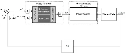
In the present study three different types of controllers for combined parameters are examined. In the first scenario, a fuzzy control that combines Frequency Containment and Inertia control is investigated. The block diagram for this controller is shown in fig. 3.
Fig. 3 Implementation of the proposed control for combined frequency containment and inertial response
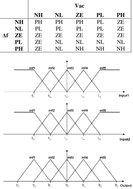
[image:2.595.315.538.610.706.2]For the frequency measurement at the point of common coupling of the power plant a PLL block can be used. The controller output is the active power of the storage system in pu. For the specific case, the set of rules of Table 1 is implemented, where NH and NL stand for Negative High and Low, ZE for Zero, and PL and PH for Positive Low and High respectively. Also, the membership functions are shown in Fig. 6.
Table 1 Rule table for the first controller-FCC1
d(Δf)/dt
NH NL ZE PL PH
Δf
NH PH PH PL PL ZE
NL PH PL PL ZE NL
ZE PH PL ZE NL NH
PL PL ZE NL NL NH
PH ZE NL NL NH NH
Similarly, in the second case the input signals are the frequency deviation and the battery State-of-Charge (fig. 4). The membership functions are also triangular and the implemented rules for this controller are shown in table 2.
Fig. 4 Implementation of proposed control for combined frequency containment and SOC management
Table 2 Rule table for the second controller-FCC2
SOC
VL LO ME HI VH
Δf
NH ZE PL PH PH PH
NL ZE PL PL PL PL
ZE ZE ZE ZE ZE ZE
PL NL NL NL NL ZE
PH NH NH NH NL ZE
Finally, the third controller makes use of frequency deviation and RMS voltage at the connection point of the storage system (Fig. 5). The rules for this controller are shown in Table 3.
For each of the controllers the values of the membership functions are summarised in the following relationships:
( ) [ ] (1)
( ) [ ] (2)
[ ] (3)
( ) [ ] (4)
( ) [ ] (5)
[image:3.595.51.281.218.312.2]Fig. 5 Implementation of the proposed control for combined frequency containment and voltage control
Table 3 Rule table for the third controller-FCC3
Vac
NH NL ZE PL PH
Δf
NH PH PH PH PL ZE
NL PL PL PL PL ZE
ZE ZE ZE ZE ZE ZE
PL ZE NL NL NL NL
PH ZE NL NH NH NH
Fig.6 Membership functions of the input/output signals for all three controller implementations
It is worth noting that for the defuzzification of the output signal, the Centre-of-Gravity method was used in all three cases.
SIMULATION RESULTS
[image:3.595.313.542.322.647.2] [image:3.595.54.281.378.475.2]power system model depicted in fig.7. This system consists of two synchronous generators 2MVA each, one PV plant (500kW) and one Battery Storage system with a maximum power capacity 300kW. The voltage levels of the selected power system vary from LV to MV, namely 0.4kV, 0.69kV, 6.3kV and 20kV. The specific power system configuration is more or less representative of island power systems and, in our case, it represents the web-of-cells. For each of the previously presented controller scenarios, with the use of the specific power system in Matlab/Simulink, one simulation scenario is selected and presented below:
Fig.7 Power system used for the simulations
In all the scenarios below, the output gain is set to -300kW, equal to the nominal active power of the storage system. Also, for the sake of convention the consumed power of the storage system (and generally in the power system) in the test results is considered as positive for consumption and negative for production.
Scenario A
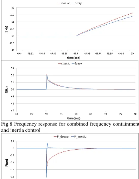
For this scenario, the control scheme of fig. 3 has been used. The controller uses two input signals, Δf and ROCOF. The gain values for this scenario are set to g1=1
and g2=0.05. For the comparison of the fuzzy controller
with a classic set of controllers (droop and inertia) two different sets of gains were used, namely Kdroop=0.25 and
Kinertia=-0.05 and Kdroop=0.5 and Kinertia=-0.025. In fig. 8
the simulation results show the frequency response when a load step-change is implemented at t=50sec. All gains are expressed pu power per Hz or per Hz/sec. Specifically, this load change is due to opening of switch B2 that leads to a disconnection of 1.07MW (thus -1.07MW power change) and 0.312MVAr. More in detail, the top diagram illustrates the initial frequency change right after the incident. The comparison is between the fuzzy controller and the first version of classic control. It is evident that the fuzzy controller deals much better with the initial ROCOF by containing it in lower values, whilst the overall frequency response of the fuzzy controller is slightly improved in terms of frequency zenith and restoration time. Also, it is worth noting that for the case of classic control, the power command that the battery system receives by the two loops, depicted in Fig.9, shows the temporarily opposing objective of the two controllers.
Fig.8 Frequency response for combined frequency containment and inertia control
Fig.9 Individual power commands produced by the two independent classic controllers-Scenario A
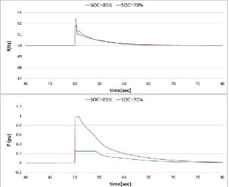
Scenario B
In this scenario, the objective is to show how a control objective such as FCC can be combined with an internal parameter such as the SOC in one controller according to Fig. 4. Specifically, the two tests implemented in this scenario regard the behaviour of the storage system under load step-change at t=50sec (in fact the disturbance is the same as in scenario A) but for two different initial values for the SOC. By combining the two objectives in one controller it is possible to exploit the resource capabilities to their full without causing problems to the battery operation. Otherwise, with the use of a classic droop controller it is possible to lead to deep discharge of the battery, reducing its lifetime.
[image:4.595.53.281.250.365.2]Scenario C
This scenario concerns the combined frequency and voltage control depicted in fig. 5.
Fig.10 Frequency and battery power response for combined frequency containment and SOC control
Fig.11 Frequency and ac-voltage response for combined frequency containment and voltage control
This test is divided into two sub-scenarios, both with g1=1 and g2=-1 and for a load change of -500kW at the
connection point of the storage system. This change may be due to load disconnection or sudden increase of the power production of the PV plant. The main difference in the two sub-scenarios is the amount of reactive power load connected at bus N-1. Thus, for scenario 1 the reactive power is 500kVAr, whereas for scenario 2 it is -800kVAr leading so to a different voltage variation during the active power change. The simulation results in fig. 11 show the frequency response (top diagram) and the N-1 voltage behaviour before and after the incident (t=50sec). The voltage deviations in both cases lead to a slight curtailment of the output power leading to an almost identical frequency response.
CONCLUSION
To cope with control conflicts that emerge by the use of multiple controllers or operating parameters on a DER unit, this study presented a method of combining multiple objectives by means of fuzzy logic. The simulation results for the various scenarios show that apart from being effective, the proposed method can also present better performance compared with classic control approaches. Despite the fact that the proposed method addresses local control issues, it is strongly linked with the ELECTRA control approaches and, in fact, provides a complementary solution to the cell-level controllers by facilitating a more efficient implementation where, due to complexity, it may be technically challenging for the cell control room to manage a multitude of local parameters.
Acknowledgments
The research leading to these results has received funding from the European Union Seventh Framework Programme (FP7/2007-2013) under grant agreement no 609687. Any opinions, findings and conclusions or recommendations expressed in this material are those of the authors and do not necessarily reflect those of the European Commission.
REFERENCES
[1] European Commission, 2014, "Strategic Energy Technology (SET) Plan-Towards an integrated roadmap: Research and innovation challenges and needs of the EU Energy System", 1-2.
[2] "e-Highway 2050" ( www.e-highway2050.eu/e-highway2050/).
[3] ENTSO-E, 2014, "10 Year Network Development Plan 2014".
[4] L. Martini, L. Radaelli, H. Brunner, C. Caerts, A. Morch, S. Hanninen, C. Tornelli, 2015, "ELECTRA IRP approach to voltage and frequency control for future power systems with high DER penetrations", Proceedings CIRED conference,1-4.
[5] K. M. Passino, St. Yurkovich, 1998, Fuzzy Control, Addison Wesley Longman, Inc., California, US, 1-70.
[6] C. Papadimitriou, N. Vovos, 2010, "A Fuzzy Control Scheme for Integration of DGs into a Microgrid", Proceedings 15th IEEE Mediterranean Electrotechnical Conference, 872-877.
[7] S. Ahmadi, S. Shokoohi, H. Bevrani, 2015,