City, University of London Institutional Repository
Citation
:
Stosic, N., Smith, I. K. ORCID: 0000-0003-1524-9880 and Kovacevic, A. ORCID: 0000-0002-8732-2242 (2003). Rotor interference as a criterion for screw compressor design. Journal of Engineering Design, 14(2), pp. 209-220. doi: 10.1080/0954482031000091518This is the accepted version of the paper.
This version of the publication may differ from the final published
version.
Permanent repository link:
http://openaccess.city.ac.uk/20590/Link to published version
:
http://dx.doi.org/10.1080/0954482031000091518Copyright and reuse:
City Research Online aims to make research
outputs of City, University of London available to a wider audience.
Copyright and Moral Rights remain with the author(s) and/or copyright
holders. URLs from City Research Online may be freely distributed and
linked to.
ROTOR INTERFERENCE AS A CRITERION
FOR SCREW COMPRESSOR DESIGN
N. Stosic, Ian K. Smith and A. Kovacevic
Centre for Positive Displacement Compressor Technology City University, London, EC1V 0HB, U.K.
Tel: + 44 20 7477 8925 Fax: +44 20 7477 8566 E-mail: [email protected]
SUMMARY Rotor clearances are mainly responsible for screw compressor leakage. They must
therefore be minimised in order to obtain high volumetric and adiabatic efficiencies of these machines. Continuing improvement in the rotor manufacturing equipment has enable tighter production tolerances to be achieved than was previously possible. Consequently, tolerances of other components, such as the rotor and bearing housings and the bearings themselves have to be included in the design process, in order to obtain the best possible overall performance.
A mathematical procedure to evaluate rotor interference in screw compressors due to bearing clearances and imperfections in the compressor housing manufacture is presented in this paper and has been used to evaluate how these affect screw compressor behaviour. It is shown that rotor interference resulting from the build up of these tolerances may affect the compressor when stationary as well as when rotating and may reduce the compressor efficiency, safety and reliability and also increase compressor noise. This simple, but effective method of quantification of the rotor interference can now be applied as a useful criterion in design of screw compressors.
1. Introduction
Screw compressors are positive displacement rotary machines comprising a meshing pair of helical rotors on parallel axes, contained in a casing. Together, these form a succession of working chambers whose volume depends on the angle of rotation.
pressure is reached when the rear ends of the passages are exposed to the discharge port through which the gas flows out at approximately constant pressure.
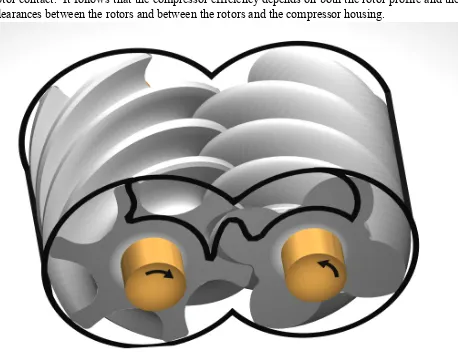
[image:3.612.80.538.151.503.2]To perform effectively, screw compressor rotors must meet the meshing requirements of gears while maintaining a seal along their length to minimise leakage at any position on the band of rotor contact. It follows that the compressor efficiency depends on both the rotor profile and the clearances between the rotors and between the rotors and the compressor housing.
Fig 1. Screw compressor rotors in their casing
Screw compressor rotors are usually manufactured on specialised machines by the use of formed milling or grinding tools. Machining accuracy achievable today is high and tolerances in rotor manufacture are of the order of 5 m around the rotor lobes. Holmes and Stephen, 1999 reported that even higher accuracy was achieved on the new Holroyd vitrifying thread-grinding machine, thus keeping the manufacturing tolerances within 3 m even in large batch production. This means that, as far as rotor production alone is concerned, clearances between the rotors can be as small as 12 m.
with smaller clearances or looser bearings with their clearances reduced to an acceptable value by preloading. The latter practice is frequently chosen as the most convenient and economic solution.
Rotor axial and radial forces are transferred to the housing by the bearings. Rolling element bearings are normally chosen for small and medium screw compressors and these must be carefully selected to obtain a satisfactory design. Usually, two bearings are employed on the discharge end of each of the rotor shafts in order to absorb the radial and axial loads separately. Also, the distance between the rotor centre lines is in part determined by the bearing size and internal clearance. Any production imperfection in the bearing housing, like displacement or eccentricity, will change the rotor position and thereby influence the compressor behaviour.
A reliable procedure is required to analyse rotor movement within the range of the bearing clearances and manufacturing imperfections of the rotor and bearing housings. This will enable bearing clearance and housing manufacturing tolerance limits to be correctly specified in order to avoid rotor interference when inter lobe clearances are reduced to the levels now possible. The following approach is a simple and effective means of doing this.
2. Identification of Rotor Movement in Compressor Bearings
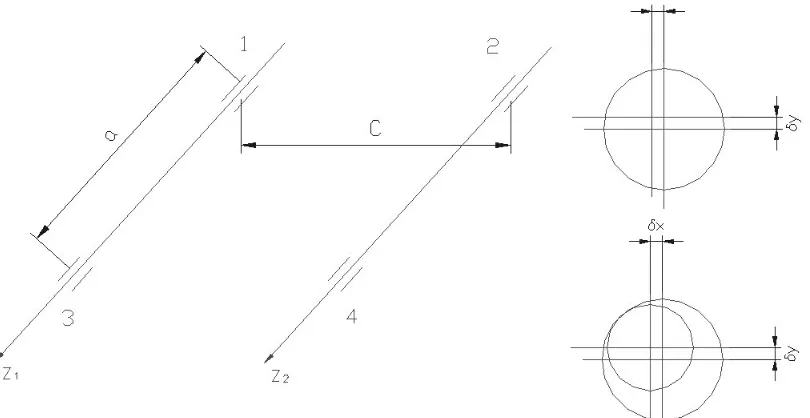
[image:4.612.104.509.408.617.2]The system of rotors in screw compressor bearings is presented in Fig 2. The rotor shafts are parallel and their positions are defined by axes Z1 and Z2.
Fig 2. Rotor shafts in the compressor housing and displacement in bearings
The bearings are labelled 1 to 4, and their clearances, as well as the manufacturing tolerances of the bearing bores, x and y in the x and y directions respectively are presented in the same
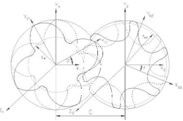
Fig 3. Rotors with parallel shafts and their coordinate systems
The envelope method for the analysis of gear motion has been described by Litvin, 1994. This is becoming increasingly popular, and details of how it may be applied to screw compressor rotor profiles, have been given by Stosic, 1998. In this procedure, vectors r1 and r2 represent the
surfaces of rotor helicoids of the main and gate rotor respectively. X01, y01 and x02, y02 are the
point coordinates at the end rotor section in the coordinate systems fixed to the main and gate rotors, as is presented in Fig 3. Equations (1) to (5) give the relation between the main and gate rotor point coordinates for a rotation angle θ, where p is the rotor lead per unit angle of rotation.
r1 r1
t,
x1,y1,z1
x01cos y01sin,x01sin y01cos,p
(1) 0 , cos sin , sin cos 0 ,
, 1 01 01 01 01
1
1
t y t x t y t x t y t x t r (2)
r2
x2,y2,z2
x1C,y1,z1
x02cos y02sin,x02siny02cos,p
(3)2
2, 2,0
02sin 02cos, 02cos 02sin,0
y x x y x y
r
(4)
1 1 2 0
r r r
Rotation of the rotor shaft is the natural rotor movement in its bearings. While the main rotor rotates through angle θ, the gate rotor rotates through angle =r1w/r2w =z2/z1, where rw and z
are the pitch circle radii and number of rotor lobes respectively.
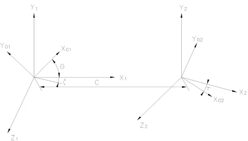
[image:6.612.103.509.201.432.2]Andreev, 1961 and, more recently, Xing, 2000, also use the envelope method for screw compressor rotor generation in their books on screw compressors. A similar approach was applied by Tang, 1995.
Fig 4. Rotors with intersecting shafts and their coordinate systems
All imperfections in the manufacture of screw compressor rotors should fall within and be accounted for by production tolerances. These are the wrong position of the bearing bores, eccentricity of the rotor shafts, bearing clearances and imperfections and rotor misalignment. Together, they account for the rotor shafts not being parallel. Let rotor movement y in the y
direction contain all displacements, which are presented in Fig 2, and cause virtual rotation of the rotors around the X1, and X2 axes, as shown in Fig 4. Let rotor movement x in the x direction
cause rotation around the Y1, and Y2 axes, as shown in Fig 5. The movement x can cause the
rotor shafts to intersect. However, the movement y causes the shafts to become non-parallel
and non-intersecting. These both change the nature of the rotor position so that the shafts can no longer be regarded as parallel. The following analytical approach enables the rotor movement to be calculated and accounts for these changes. It was first presented by Stosic et al, 2001.
As shown in Fig 4, vectors r1=[x1,y1,z1] and r2, given in equation (6) now represent the helicoid
surfaces of the main and gate rotors on intersecting shafts. The shaft angle , given by (4) is the rotation about Y.
a
tg x (7)
Since this rotation angle is usually very small, equation (6) can be rewritten in a simplified form as equation (8), which can be used more easily for further analysis.
r2
x2,y2,z2
x1z1 C,y1,x1z1
(8)The rotation will result in a displacement –z1 in the x direction and a displacement x1 in
the z direction, while there is no displacement in the y direction. The displacement vector becomes:
r2
z1,0,x1
(9)In the majority of practical cases, x1 is small compared with z1 and only displacement in the x
direction need be considered. This means that rotation around the Y axis will practically change the rotor centre distance only. Displacement in the z direction may be significant for the dynamic behaviour of the rotors. Displacement in the z direction will be adjusted by the rotor relative rotation around the Z axis, which can be accompanied by significant angular acceleration. This may cause the rotors to lose contact at certain stages of the compressor cycle and thus create rattling, which may increase the compressor noise.
Since the rotation angle caused by displacement within the tolerance limits is very small, a two-dimensional presentation in the rotor end plane can be applied, as is done in the next section.
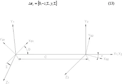
As shown in Fig 5, vectors r1=[x1,y1,z1] and r2, given by equation (10) now represent the
helicoid surfaces of the main and gate rotors on the intersecting shafts. is the rotation angle around the X axes given by (11).
r2
x2,y2,z2
x1C,y1cosz1sin,y1sinz1cos
(10)
a tg y
(11)
Since angle is very small, equation (10) can be rewritten in simplified form as equation (12), which facilitates further analysis.
r2
x2,y2,z2
x1C,y1z1,y1z1
(12)The rotation will result in displacement –z1 in the y direction and displacement y1 in the z
r2
0,z1,y1
(13)Fig 5. Rotors with non-parallel and non-intersecting shafts and their coordinate systems
Although, in the majority of practical cases, displacement in the z direction is very small and therefore unimportant for consideration of rotor interference, it may play a role in the dynamic behaviour of the rotors. The displacement in the z direction will be fully compensated by a regular rotation of the rotors around the Z axis. However, the angular acceleration involved in this process may cause rotors to lose contact at some stages of the compressor cycle.
Rotation about the X axis is effectively the same as if the main or gate rotor rotated relatively through angles =-z1/r1w or =z1/r2w respectively and the rotor backlash will be reduced by
z1. Such an approach substantially simplifies the analysis and allows the problem to be
presented in two dimensions in the rotor end plane.
3. Rotor Interference Presented in the Rotor End Plane
Although the displacements described in this paper are entirely three-dimensional, a two-dimensional presentation of them in the rotor end plane section can be used for analysis.
Equation (3) serves to calculate both the coordinates of the rotor meshing points x2, y2 on the
rotor helicoids and x02, y02 in the end plane from the given rotor coordinates points x01 and y01. It
proximate rotor position. A convenient practice to obtain a clearance gap between the rotors is to consider the gap as the shortest distance between the rotors in a section normal to the rotor helicoids. The end plane clearance gap can then be obtained from the normal clearance by appropriate transformation.
If is the normal clearance between the rotor helicoid surfaces, the cross product of the r
derivatives, given in the left hand side of equation (5), which defines the direction normal to the helicoids, can be used to calculate the coordinates of the rotor helicoids xn and yn from x and y to which the clearance was added as:
) ( , , dt dy y dt dx x D z dt dx D p y y dt dy D p x
xn h n (14)
where the denominator D is given as:
2 2 2 2 dt dy y dt dx x dt dy p dt dx p
D (15)
The xn and yn serve to calculate new rotor end plane coordinates, x0n and y0n, with clearances
from equations (1) and (3) for angles =zn/p and respectively. X0n and y0n now serve to calculate the transverse clearance 0 as the difference between them, as well as the original rotor
coordinates x0 and y0.
A 4/6 rotor pair is chosen as an example to present the rotor interference caused by imperfections in compressor manufacturing. The rotor centre distance is 75 mm and the outer rotor diameters are 99.00 and 93.36 mm for the main and gate rotors respectively. The rotor length is 153.5 mm and the unit lead is 25.24 mm/rad. The bearing span is 200 mm. There is assumed to be a uniform clearance between the rotors of 85 m.
For the purpose of this analysis, the rotors are fixed in their suction bearings and the whole bearing displacement is applied to one of the discharge bearings. The aggregate displacement of all the bearings is x=y=50 m, which reduces the rotor centre distance by a maximum of 44 m
and imposes a rotation of 0.06o on the gate rotor.
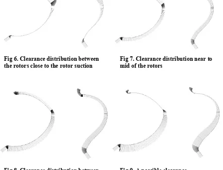
Both the rotors, with their corresponding clearance distribution scaled by a factor of 50, are shown in figs 6-14.
Fig 6. Clearance distribution between the rotors close to the rotor suction
Fig 7. Clearance distribution near to mid of the rotors
Fig 8. Clearance distribution between
the rotors at the discharge rotor end
Fig 9. A possible clearance
distribution at the discharge end
If by any means, the rotors change their relative position, the clearance distribution at the discharge end of the rotors may be reduced to zero at the flat side of the rotor lobes, as presented in Fig 9. In such a case, rotor contact will be prohibitively long on the flat side of the profile, where the dominant relative rotor motion is sliding. This indicates that rotor seizure will almost certainly occur in that region if the rotors come into contact with each other.
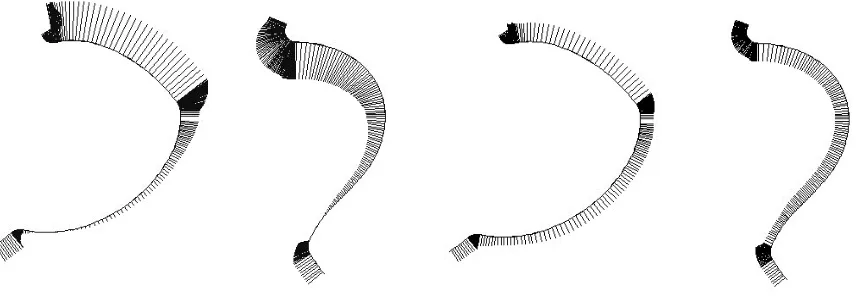
[image:10.612.123.451.685.786.2]Fig 10. Variable clearance distribution applied to the rotors
Fig 11. Clearance distribution
between the rotors close to suction
Fig 12. Clearance distribution near to mid of the rotors
Fig 12. Clearance distribution between the rotors at the discharge
Fig 13. A possible clearance distribution at the discharge
4. Dynamic Effects of Rotor Interference
Apart from the static effects of rotor interference, which are described in the previous section, some dynamic effects may be caused by the incorrect rotor position in its housing. Two examples are related to oil flooded compressors.
The first example, presented here, is the non-uniform movement of the gate rotor caused by displacement of the rotor contact point in the z direction. Since such displacements as x1 and y1, defined by Eqs. (7) and (11), are variable, they cause variable relative
rotation of the rotors, which will result in a non-uniform movement of the gate rotor regardless of whether or not the rotors are conjugate. This will inevitably cause oscillations of the gate rotor and the eventual generation of rotor noise.
6. Conclusions
Screw compressor rotors are manufactured today with very tight tolerances by formed grinding tools. This permits small rotor clearances, which leads to more efficient screw compressors. However, small rotor clearances cause production imperfections in the screw compressor housings and bearings, to have a far greater significance.
A simple mathematical analysis, derived in the paper, has been applied to quantify the static and dynamic effects of the rotor interference in screw compressors caused by the manufacturing imperfections of the screw compressor housings and bearings. This may be used as a design criterion to enable compressor manufacturers to choose tolerances for these components which enable the full performance benefits of high precision compressor rotors to be achieved in these machines without increased likeliehood of noise or seizure.
REFERENCES
Andreev P. A, 1961: Vintovie kompressornie mashinii (Screw Compression Machines), SUDPROM Leningrad, Russia
Edstroem S. E, 1992: A Modern Way to Good Screw Compressor Rotors, International Compressor Engineering Conference at Purdue, 18
Holmes C. S. and Stephen A. C, 1999: Flexible Profile Grinding of Screw Compressor Rotors, International Conference on Compressors and Their Systems, IMechE London
Litvin F, 1994: Gear Geometry and Applied Theory, Prentice Hall, Englewood Cliffs
Stosic N, 1998: On Gearing of Helical Screw Compressor Rotors, Proc IMechE, Journal of Mechanical Engineering Science, Vol 212, 587
Stosic N, Smith I. K and Kovacevic A, 2001: Calculation of Rotor Interference in Screw Compressor, International Compressor Technique Conference, Wuxi, China
Tang Y, 1995: Computer Aided Design of Twin Screw Compressors, PhD Thesis, Strathclyde University, Glasgow