copyright. DOI: 10.4271/2015-01-2404
Page 1 of 10
2015-01-0.174
Protection System Considerations for DC Distributed Electrical Propulsion Systems
*C.E. Jones, *K. Davies, *P. Norman, *S. Galloway, *G. Burt,
+M. Armstrong,
+A. Bollman.
*University of Strathclyde, + Rolls-Royce North American TechnologiesAbstract
Distributed electrical propulsion for aircraft, also known as turbo-electric distributed propulsion (TeDP), will require a complex electrical power system which can deliver power to multiple propulsor motors from gas turbine driven generators. To ensure that high enough power densities are reached, it has been proposed that such power systems are superconducting. Key to the development of these systems is the understanding of how faults propagate in the network, which enables possible protection strategies to be considered and following that, the development of an appropriate protection strategy to enable a robust electrical power system with fault ride-through capability. This paper investigates possible DC protection strategies for a radial DC architecture for a TeDP power system, in terms of their ability to respond appropriately to a DC fault and their impact on overall system weight and efficiency. This latter aspect has already been shown to be critical to shaping the overall TeDP concept competitiveness.
Introduction
There is strong motivation to develop future aircraft which have lower emissions and higher performance than current state of the art aircraft, in order to meet the expected future demand for air travel and mimimise the environmental impact of such aircraft [1, 2]. TeDP has been proposed as a possible solution to enable such targets to be reached, with NASA aiming to reach a technology readiness level of 4-6 by 2025 [3].
[image:1.612.332.573.202.409.2]However, TeDP represents a radical change from current state of the art aero-electrical systems. Firstly these electrical power systems are much more complex and require a much higher level of onboard generation. For a 300pax aircraft, an estimated 50MW of generated power capacity is required [4], compared to 1.5MW on an equivalent state of the art more-electric aircraft [5]. Secondly, due to the increase in the size of the aero-electrical power system, it has been proposed that superconducting electrical machines are used, in order that high enough power densities can be achieved [6]. In order to avoid heat sink penalties, it is proposed that the entire system be superconducting, as far as is technologically possible [4]. However, a superconducting system requires a cryogenic cooling system, which attracts a significant weight and efficiency penalty [4, 7].
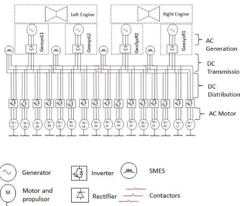
Figure 1: Example TeDP architecture with DC transmission and distribution network shown without any protection system present.
An example distributed electrical propulsion architecture is shown in Fig. 1[Error! Reference source not found.]. The generated power from the generators and the power input to the propulsor motors will be 3-phase AC power. However the transmission and distribution system within this architecture has been chosen to be DC. This has two key advantages. Firstly it enables the electrical decoupling of the high speed generators from the lower speed, higher torque propulsor motors. It is proposed that in order to achieve high propulsive efficiency, the gas turbine core driven generators should be run at a high shaft speed [6, 9]. Secondly it is proposed that energy storage be included in the system. Whilst the role of the energy storage has yet to be fully defined, and is outside the scope of this paper, it is expected that it will provide voltage support to the system in response to system transients. In order to control the contribution of the energy storage to the network, it is proposed that it will be interfaced to the network via a converter [4]. If the network is DC, then it may be possible to use a simpler, and hence lighter and more efficient, converter than if an AC-DC converter is used.
copyright. DOI: 10.4271/2015-01-2404
Page 2 of 10
impact of cable weight and losses on the overall system performance is negligible compared to that of the solid state switching components [7].
Key to the safe operation of the system is the development of an appropriate protection and fault management strategy, which will at the very least enable an aircraft to continue to fly and land safely should an electrical fault occur. This paper will firstly discuss the requirements of the DC protection system for the example TeDP network shown in Fig. 1. Secondly a transient simulation based case study to investigate the propagation of faults in a section of the DC network is presented and the implications for protection discussed. As part of these discussions, the impact of possible protection solutions on the weight and efficiency of the full electrical power system are considered using a pre-design sensitivity analysis tool developed by the authors [7].
Considerations for the development of DC
protection for TeDP network
Central role of protection system in an aero-electrical
power system
Aero-electrical systems require an adequate protection system to ensure that the occurrence of an electrical fault does not present a safety risk to the aircraft and its occupants, and ultimately to enable the aircraft to continue in flight and land safely afterwards. Appropriate power quality standards for TeDP aircraft however have yet to be developed [11]. To develop an understanding for what performance requirements may be expected from a TeDP aircraft in the event of an engine out or loss of propulsor scenario, current FAA and European Aviation Safety Agency (EASA) Extended Operations (ETOPS) regulations are considered [12, 13]. The standards stipulate the performance requirements of a remaining, healthy engine if the other engine on a twin engine aircraft has failed. The aircraft must be able to safely fly for a certain amount of time on a single engine and land safely. There must be sufficient power (electrical, hydraulic and pneumatic) available to enable this. The most recently developed state-of-the-art aircraft have an ETOPS range of up to 370 minutes [14]. It is expected that similar standards will be developed for TeDP aircraft in order that the aircraft is able to cope with an engine out scenario.
Therefore the proposed components which make up the TeDP electrical network have been overrated to enable single engine operation in case of an engine out scenario [4]. The maximum power required by the example system is 22.4MW for a rolling take-off [15]. Under this scenario, each of the 16 propulsor motors will draw circa 1.4MW. To allow for an engine out scenario the generators are rated at 12.5MW. In addition, the propulsor motors are rated at 2.5MW to allow for scenarios where only 14 out of the 16 propulsor motors are operational. The candidate TeDP network in Fig. 1 is comprised of 4 identical sub-networks, with 4 generators each powering 4 propulsor motors. There are contactors, which are nominally open, between the 4 sub-networks to allow re-routing of power from one sub-network to another in the case of a fault. Parallel cables and feeders are also utilised (not shown in the diagram) to provide additional redundancy [4].
Howev er in additio
n to
this overrat ing, a suitabl e protect ion and fault
[image:2.612.326.604.11.185.2]management strategy is required to isolate electrical faults, prevent fault propagation and protect healthy sections of the TeDP network in the event of a fault. Ideally, a protection and fault management system should also allow for an aero-electrical system to have fault
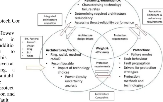
Figure 2: interdependencies between the three key areas of power system design and collective impact on system weight and efficiency.
ride-through capability, enabling a system to recover from a fault after it has cleared, and protect the non-faulted system when a fault occurs.
The choice of protection system will be influenced by the choice of network architecture (whether it is ring, radial or meshed radial for example) [16]. The choice of converters utilised for the generator interfaces will impact on the fault response of the system. If conventional voltage source converters (VSCs) are used then a short circuit fault will, in the absence of any suitable protection system, cause the filter capacitors to discharge, resulting in a high peak fault current [17].
Therefore the design of a protection system for a distributed electrical propulsion system both influences, and is influenced by, the power system architecture and approaches taken to provide redundancy and reliability in power system design. As Fig. 2 illustrates, a holistic view to the design of the full power system must be taken in order to develop a system which meets weight and efficiency (and hence fuel burn) targets [7].
Sensitivity of fault response of system to network
parameters
To development a suitable protection system, the fault response of a superconducting electrical power system must first be considered. This is dependent on a number of factors which include both parameters specific to the choice of cable (resistivity, cross-sectional area), and operating conditions (voltage level, length of cable) [18].
If the current in a superconducting cable exceeds a critical current level, Ic (A), defined in (1) then the resistance of the cable will start to rise at a rate of kquench, until the quenched resistance (Rquenched), defined in equation (2) is reached [18]. Once this occurs, the resistance of the cable continues to rise at a rate of kcreep due to increased heat dissipation as quenching occurs.
𝐼𝑐 = 𝐽𝑐× 𝑎𝑐𝑎𝑏𝑙𝑒 (1)
𝑅𝑞𝑢𝑒𝑛𝑐ℎ𝑒𝑑 =(𝜌𝑎𝑚𝑏𝑖𝑒𝑛𝑡𝑙 ×𝑎𝑐𝑎𝑏𝑙𝑒)
copyright. DOI: 10.4271/2015-01-2404
Page 3 of 10
Jcis the critical current density of the cable (A/m2) and acable is its cross-sectional area (m2). ρambient is the resistivity of the superconducting material at the ambient temperature of the system (77K in this case) (μΩm) and lcable is the length of the cable (m).
The peak magnitude of fault current, and hence the likelihood that a cable will quench, has been shown in [18] to be most sensitive to the cable diameter and length. The physical size of the proposed TeDP aircraft is such that if the generators are located within wingtip mounted gas turbines, then there may be 40m between the generators and the propulsor motors [8]. Hence, when considering the propagation of a fault in a network, it is important to consider that the length of the cable will impact on the peak fault current, and whether quenching is likely to occur. However, the studies presented in [18] did not consider how a fault would propagate through a TeDP DC network. This will be investigated in this paper.
Consideration of protection options
Minimum requirements of a protection system
A protection system must ensure that any electrical fault which occurs on the network does not impact on the safety of the aircraft. For an aero-electrical system this means that in the event of an electrical fault occurring, firstly the aircraft must be able to land safely. In addition to this, protection must prevent fire and the possibility of sections of the aircraft becoming live in a fault scenario [19].
In order to achieve this, the protection system must reliably trip when a fault occurs, and it must trip fast enough to ensure that a fault can be isolated. Additionally the protection system should be as simple as possible, in order to ensure the reliability of the protection system. Further to this, for an aerospace application where weight and efficiency require to be kept to a minimum, a simpler protection system may also be lighter and more efficient. Hence it will have less of a negative impact on fuel burn. For compact electrical networks, such as those proposed for distributed propulsion systems, high levels of selectivity may be required in order to maintain supply to critical loads [Error! Reference source not found.].
For aero-electrical applications, the weight of the protection system will impact on system performance (fuel burn) [17], hence there is motivation to optimize the protection system towards this objective in addition to providing an adequate level of systems safety. For a superconducting electrical network, the impact of a protection system on the network’s efficiency must also be considered. This is because losses will be dissipated as heat, which is subsequently removed from the system via a cryocooling system. Hence a lower efficiency will result in an increase in the required rating of the associated cryocooling system, increasing the total system weight and decreasing system efficiency [7]. Ultimately this will have a significant negative impact on system performance by increasing fuel burn, could potentially account for over 1/3 of the system weight and losses [4,7]. The size and power of the required cryocooling system can be estimated using equations (3) to (5) [20].
𝑃𝑐𝑟𝑦𝑜 =𝜂 𝑄̇ 𝑐𝑎𝑟𝑛𝑜𝑡
(𝑇𝑎𝑚𝑏−𝑇𝑐𝑜𝑜𝑙)
𝑇𝑐𝑜𝑜𝑙 (3)
𝑊𝑐𝑟𝑦𝑜 = 𝑘 × 𝑃𝑐𝑟𝑦𝑜 (4)
𝜂𝑓𝑢𝑙𝑙 =𝑃 𝑃𝑚𝑜𝑡𝑜𝑟
𝑚𝑜𝑡𝑜𝑟+𝑃𝑐𝑟𝑦𝑜+𝑃𝑒𝑙𝑒𝑐 𝑙𝑜𝑠𝑠𝑒𝑠 (5)
Pcryois the power required by a cryocooler (W) which is operating at a Carnot efficiency, ηcarnot, (taken to be 30%) with an ambient temperature, Tamb ,(300K) and a coolant temperature,Tcool, (100K for the solid state switching components, 77K for superconducting components) and 𝑄̇ is the heat flow to the coolant (W). Wcryo is the weight of the cryocooler, with a power density k of 3kW/kg. ηfull is the full system efficiency, which is a function of the total power demanded by the motors, Pmotor, the cryocooler power requirements
Pcryo and the electrical losses in the system Pelec_losses.
The weight and efficiency targets set for aero-electrical applications potentially discourage over-protecting the network. Hence for a distributed electrical propulsion system, there is a need to firstly consider what the fault response of the network is. Secondly to then consider protection options and how they will respond to a fault. Thirdly to investigate what impact the candidate protection options would have on system weight and efficiency.
Protection hardware options
If no protection is in place, then it is expected that the network will quench in response to the fault if the fault current is higher than the critical current for the cables. If the system does quench then this will lead to questions regarding how much of the system will quench, how quickly it will recover from a quench and how the system is reconfigured during a quench event in order to ensure the safety of the aircraft. If a quench does occur then this may also result in damage to equipment due to local heating associated with the quench.
However, an alternative approach is to actively respond to a fault in a timely manner in order to prevent quenching occurring. This is achieved by implementing a suitable protection system. Firstly the converter could be designed to provide fault current blocking capability [8]. This can be achieved in two ways: Either a voltage source converter with snubbers on the DC side capacitance to limit the di/dt [19], or to take advantage of the fault current blocking capability of a current source converter [8]. However, whilst these converters will block fault current from propagating to other sections of the network, the faulted section of network may still quench if there is enough source current to create a local overcurrent condition at the point of the fault [18].
copyright. DOI: 10.4271/2015-01-2404
Page 4 of 10
microseconds for an SSCB), SFLCs are still considered for distributed electrical propulsion systems.
Fault response of a section of DC TeDP network
Fault response of the system
Before the suitability of different protection strategies can be assessed, the fault response of the system must first be characterized. A section of a TeDP network is modelled as shown in Fig. 3 which represents four propulsors (Rload1-4) connected to the output of one
voltage source converter (VSC). The cables are represented by an inductance (Ltransmission, Ldistribution1-4) in series with a variable
resistance (Rtransmission, Rdistribution1-4) which is 0 Ω under normal
operating conditions. The quench behaviour of the cables has been described previously in equations (1) and (2). A rail to rail short circuit (Rfault) is also placed across one of the four distribution cables
after 1 ms of simulation time, leading to the discharge of the filter capacitor CF. Table 1 shows the network parameters used for this
and subsequent simulation studies.
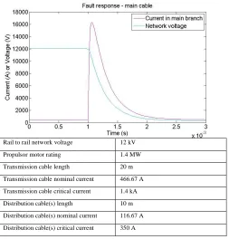
Fig. 4 shows the network voltage (VCF(t)) and the transmission cable
current when no protection is modeled in the system. It can be seen the network voltage collapses from 12 kV to near-zero and the current carried in the transmission cable increases significantly from 466.67 A, reaching a peak of 16.3 kA, 60 μs after the fault. Figs. 5 and 6 show the currents carried in each of the transmission and distribution cables before and after the fault. From these figures, it can be seen that the current in the transmission cable and the faulted distribution cable rises, whilst the current in the distribution cables of the healthy network branches falls to zero. This rise in fault current causes both the faulted distribution cable and the transmission cable to quench, as their critical currents are both exceeded. To illustrate this effect, fig. 7 shows the critical current ratings for both cables overlaid on traces of the measured currents during the fault event, illustrating the instances of quench initiation. From this figure, it can be seen from fig. 7 that the faulted distribution cable quenches 0.22 μs after the fault and the transmission cable quenches 1.63 μs after the fault.
[image:4.612.326.579.113.377.2]Figure 3: Subsection of DC network for examining the response to a fault on the DC distribution system.
Table 1. Simulation parameters
Rail to rail network voltage 12 kV
Propulsor motor rating 1.4 MW
Transmission cable length 20 m
Transmission cable nominal current 466.67 A
Transmission cable critical current 1.4 kA
Distribution cable(s) length 10 m
Distribution cable(s) nominal current 116.67 A
[image:4.612.330.555.418.570.2]Distribution cable(s) critical current 350 A
[image:4.612.40.251.495.590.2]Figure 4: Fault response of the transmission cable.
copyright. DOI: 10.4271/2015-01-2404
[image:5.612.44.269.82.232.2]Page 5 of 10
[image:5.612.42.271.326.498.2]Figure 6: Fault currents in the transmission, faulted distribution and healthy distribution cables at time of fault.
Figure 7: Quench timings of the transmission cable and faulted distribution cable.
Protection system trades
Identification of protection system strategies
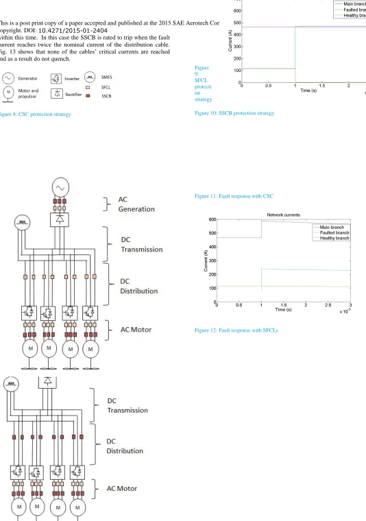
Three different approaches to protecting the system were investigated. These were firstly to use current-source converters (CSC) (illustrated in fig. 8), secondly to use SFCLs (illustrated in fig.9) and thirdly to use SSCBs (illustrated in fig.10).
If CSCs (or indeed other current limiting converter technologies) are employed, the need for a filter capacitor is removed, hence the fault response is no longer dominated by the capacitor discharge. Figure 11 shows the measured current profiles for the transmission cable, and faulty and healthy distribution cables. It can be seen that the current in the healthy distribution cables falls to nearly zero as a
result of the collapse in network voltage and the fault current flows through the faulted distribution cable. This causes the faulted cable to quench as its critical current is surpassed. Additionally, as the transmission cable sees no significant change in current it remains unquenched. Interestingly, even after the faulted distribution cable has quenched, it continues to draw significantly more current than the remaining healthy branches. In this particular case, although the quenched cable has increased significantly in impedance, the total fault path impedance is still notably lower than the effective impedance of the motor loads supplied by the remaining healthy branches. Hence the fault still draws the majority of the current from the source, depriving the remaining motor loads of their supply (although this ratio of quenched fault path impedance and remaining load impedance is highly sensitive to the architecture design and voltage level). The use of additional contactors would be required here to physically isolate the faulted section of the network and restore the power supply to the remaining propulsion motors. The required operating time of these contactors would be shaped by the maximum permissible supply interruption period for the motors before a noticeable reduction in thrust occurs.
The second protection strategy considered is the employment of SFCLs to limit the fault current and avoid the quenching of both the transmission and distribution cables. In order to ensure that neither cable will quench, a SFCL is placed on the distribution branch, which is rated to quench when the current reaches two thirds of the distribution cable’s critical current. The SFCL must limit the fault current below the distribution cable’s critical current within 0.22 μs of the fault occurrence; hence the quench rate of the SFCL is set to a very high arbitrary value of 1x10⁹Ω/s. Fig. 12 shows the fault response in each of the cables in the network. The SFCL quenches 0.09 μs after the fault and reduces the fault currents in the faulted distribution cable and the transmission cable to approximately 240A and 590 A respectively. Therefore, neither cable quenches.
copyright. DOI: 10.4271/2015-01-2404
Page 6 of 10
[image:6.612.326.592.7.161.2]within this time. In this case the SSCB is rated to trip when the fault current reaches twice the nominal current of the distribution cable. Fig. 13 shows that none of the cables’ critical currents are reached and as a result do not quench.
[image:6.612.40.574.13.773.2] [image:6.612.47.270.225.776.2]Figure 8: CSC protection strategy
Figure 9: SFCL protecti on strategy
Figure 10: SSCB protection strategy
Figure 11: Fault response with CSC
copyright. DOI: 10.4271/2015-01-2404
Page 7 of 10
Figure 13: Fault response with SSCBs
Trades between protection strategies and system performance
[image:7.612.54.277.80.229.2]Different protection system approaches will have different impacts on system weight and efficiency, and hence system performance. Investigation of the fault response of the AC sections of network is outside the scope of this paper, however to investigate the impact of different protection strategies on performance, the full system architecture shown in fig. 1 is considered. Hence a notional AC protection system has been included, with SSCBs and SFCLs included to protect the converters and electrical machines from any AC side faults.
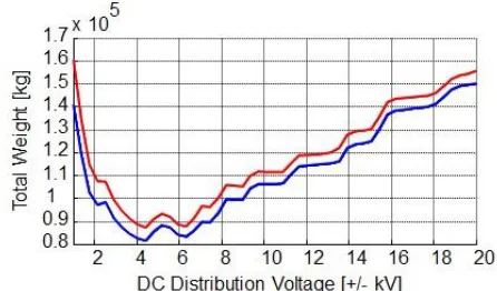
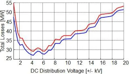
[image:7.612.334.557.432.563.2]Table 2 shows the total weight and losses of the combined electrical and cryocooling systems for the three protection options presented in the previous section. It can be observed that the impact of the SFCL on the system weight and efficiency is very low. The SSCBs have a much greater impact, accounting for 4.79% of the total weight of the electrical and cryocooling, and just under 5% of the total losses. Figs. 14 and 15 show the results of a DC voltage sweep for the different protection options considered, for the total system weight (fig. 14) and system losses (fig. 15). The results for the CSC only and SFCL DC protection are almost identical due to the limited impact of the SFCLs on system performance. These results indicate that the optimal operating voltage of the system is circa +/- 4 kV to +/- 6 kV. All of these results include the weight and power requirements of the cryocooling system. Finally the results indicate the considerable impact that the full protection system (considering the AC and DC protection systems) has on system performance.
Table 2. Contribution of different components to the total weight and losses of the combined electrical and cryocooling system at +/-6kV DC voltage.
% Total weight % Total losses
Case (CSC) Case 2 (SFCL)
Case 3 (SSCB)
Case 1 (CSC)
Case 2 (SFCL)
Case 3 (SSCB)
Converters 72.86 72.86 69.38 76.62 76.62 72.79
AC protection 18.8 18.8 17.90 20.21 20.21 19.20
DC protection - 0.0003 4.79 - 9x10⁻⁶ 4.98
Electrical
Machines 5.74 5.74 5.46 1.86 1.86 1.79
SMES 2.36 2.36 2.25 1.25 1.25 1.19
Cables 0.23 0.23 0.21 0.05
.0
0.05
.0
0.04
Discussion
copyright. DOI: 10.4271/2015-01-2404
[image:8.612.51.274.111.239.2]Page 8 of 10
Figure 14: Comparison of total system weight (combined electrical and cryocooler system) for the different protection strategies. (Red is for case 1 (CSC) and 2 (SFCL), blue is for case 3 (SSCB)).
Figure 15: Comparison of total system (combined electrical and cryocooler system) losses for the different protection strategies. (Red is for case 1 (CSC) and 2 (SFCL), blue is for case 3 (SSCB)).
impedance of the remaining loads). Under these conditions, a single electrical fault could result in the loss of thrust from all propulsors in that particular section of the network.
The results presented in this paper indicate that the use of CSCs as the sole protection for the DC transmission and distribution network on a TeDP architecture is very challenging if quenching is to be avoided. As a result, whilst utilizing CSCs as a protection system component in addition to their primary power conversion role minimizes the impact of the protection system on the aircraft performance (i.e. negligible additional mass and efficiency penalties), additional contactors are still likely to be required for physical fault isolation following the quenching of the faulted cable in order to restore the supply of power to nearby the healthy feeders.
Results presented in this paper indicate that appropriately rated SFCLs and SSCBs may be possible DC protection options. When either SFCLs or SSCBs are used to protect the system, the results indicate that the healthy sections of the distribution network continue to operate as normal (with minimal transient behavior) after the fault has occurred and the protection has operated. The performance of the SFCL does prevent the faulted cable from quenching, although the current drawn by the faulted branch does increase by 40%, which may require components to be overrated to be able to withstand higher currents during a faulted condition. This will impact on system weight and efficiency, and has not been considered in the results presented in Table 2 or figs. 13 and 14. Further studies are required to ascertain what level of overrating of components would be required to accommodate for these conditions and whether, like with the CSC, additional isolating contactors would be required for physical isolation. The approach using SSCBs has a much greater impact on system performance, contributing around 5% to the total system weight and losses. However the advantage of the SSCB is that it isolates the faulted branch completely. Therefore no extra current is drawn from the generator fed rectifier.
The results presented in Table 2 also show the significant impact that the full protection system (for both the AC and DC sections of the TeDP power system architecture) has on the overall system
performance. This firstly indicates the importance of developing a protection system for future TeDP aircraft which is optimized for safety, mass and efficiency. Secondly it indicates the importance of the protection system in the holistic design process of a TeDP electrical power system. Its impact is not insignificant and it must be considered from an early stage, alongside redundancy and architecture options. Finally, this paper has not considered the impact that future improvements to the performance of SSCBs, in particular if the losses from these devices could be reduced. The losses contribute significantly to the cryocooler requirements, impacting negatively on weight and efficiency [7]. If the performance of these devices changes significantly, it may impact on decisions surrounding choice of protection system.
Conclusions and recommendations
A key enabler to the development of a TeDP system that has a DC transmission and distribution system is the development of a suitable protection strategy. It is clear that firstly a decision about whether it is acceptable for a faulted superconducting cable to quench in response to a fault must be made. It can be concluded from the study presented that for the architecture considered, that if one DC distribution branch cable quenches, then as a result, reduced current could be supplied to the remaining 3 propulsor motors in that section of network until the fault is physically isolated from the network by some other means.
Therefore a protection strategy to prevent quenching occurring and enabling the TeDP DC architecture to have fault ride through capability is required. This will use either SFCLs, or SSCBs, or a combination thereof is required. CSCs or other current limiting converter topologies may also be important for limiting fault current at the source. SSCBs, if available at the required ratings in 2035, provide the most comprehensive protection solution, but at the greatest cost to system weight and efficiency. Using the SSCBs as a multirole protection and control device (in a manner akin to present-day SSPCs [23]) may potentially make these costs more acceptable from a holistic design point of view however.
In order to develop TeDP protection solutions further, there is a need to first develop a protection system evaluation framework for TeDP power systems. By combining the output of this capability with considerations for system redundancy and performance (weight and efficiency), the authors will continue to work towards developing an optimum protection strategy to enable safe and robust TeDP power systems to be developed.
References
1. Luongo, C.A., Masson, P. J., Nam, T., Mavris, D., et al, “Next Generation More-Electric Aircraft: A Potential Application for HTS Superconductors”, IEEE Transactions on Applied Superconductivity, 9(3): 1055-1068 2009, doi: 10.1109/TASC.2009.2019021
2. Kim, H. D., Brown, G.V., and Felder, J.L., “Distributed Turboelectric Propulsion for Hybrid Wing Body Aircraft”, International Powered Lift Conference, 2008.
3. Felder, J.L., Brown, G.V., Kim, H.D., and Chu,
copyright. DOI: 10.4271/2015-01-2404
Page 9 of 10
4. Armstrong, M. Blackwelder, M. and Ross, C., “Sensitivity of TeDP Microgrid Systems Weight and Efficiency to Operating Voltage”, AIAA Joint Propulsion Conference, 2014
5. Karimi, K.J., “Future Aircraft Power Systems – Integration Challenges”, available online from:
https://www.ece.cmu.edu/~electriconf/2008/PDFs/Karimi.pdf, ,
website accessed 30th March 2015
6. Brown, G.V., “Weights and Efficiencies of Electric Components of a Turboelectric Aircraft Propulsion System”, 49th
AIAA Aerospace Sciences Meeting, USA, 2011
7. Jones, C.E., Norman, P.J., Galloway, S.J., Burt, G.M., et al, “A Pre-Design Sensitivity Analysis Tool for Consideration of Full-Electric Aircraft Propulsion Full-Electrical Power System
Architectures”, International Conference on Electrical Systems for Aircraft, Railway , Ship Propulsion and Road Vehicles, 2015 8. Ross, C., Armstrong, M., Blackwelder, M., Jones, C. et al.,
"Turboelectric Distributed Propulsion Protection System Design Trades," SAE Technical Paper 2014-01-2141, 2014,
doi:10.4271/2014-01-2141.
9. Felder, J.L., Brown, G.V., Kim, H.D., Chu, J., “Turboelectric Distributed Propulsion in a Hybrid Wing Body Aircraft,” International Symposium on Air Breathing Engines, 2011 10. Felder, J.L, Tong, M.T., Chu, J., “Sensitivity of Mission Energy
Consumption to Turboelectric Distributed Propulsion Design Assumptions on the N3-X Hybrid Wing Body Aircraft”, AIAA-2012-3701 Joint Propulsion Conference, 2012
11. Bollman, A.M., Armstrong, M. J, Jones, C.E., Norman, P.J. et al, “Development of Voltage Standards for a Power System in a Turbo-electric Distributed Propulsion Aircraft”, International Conference on Electrical Systems for Aircraft, Railway , Ship Propulsion and Road Vehicles, 2015
12. Federal Aviation Administration, “Advisory Circular on Extended Operations (ETOPS and Polar Operations)”, Document number 120-42B, June 2008
13. European Aviation Safety Agency, “AMC 20-6 rev 2 – Extended Range Operation with Two-Engine Aeroplanes ETOPS Certification and Operation” 23 December 2010 14. European Aviation Safety Agency, “EASA certifies Airbus
A350 XWB for up to 370 minute ETOPS”, accessed March 2015 http://www.easa.europa.eu/
15. Armstrong, M.J., Ross, C.A.H., Blackwelder, M.J., “Trade Studies for NASA N3-X Turboelectric Distributed Propulsion System Electrical Power System Architecture”, SAE Int. J. Aerospace, 5(2):2012, doi: 10.4271/2012-01-2163 16. Fletcher, S., Norman, P., Rakhra, P., Galloway, S., et al,
“Modelling and Simulation Enabled UAV Electrical Power System Design”, SAE Int. J. Aerosp. 4(1):1074-1083, 2011, doi:10.4271/2011-01-2645
17. Fletcher, S.D.A., Norman, P.J., Galloway, S.J., Burt, G.M., “Determination of Protection System Requirements for DC Unmanned Aerial Vehicle Electrical Power Networks for Enhanced Capability and Survivability,” IET Electrical Systems in Transportation 1(4):137-147, 2011, doi: 10.1049/iet-est.2010.0070.
18. Davies, K.M., Norman, P.J., Jones, C.E., Galloway, S. J., et al, “Fault Behaviour of a Superconducting Turboelectric
Distributed Propulsion Aircraft Network: A Comprehensive Sensitivity Study”, International Conference on Electrical Systems for Aircraft, Railway , Ship Propulsion and Road Vehicles, 2015
19. Cuzner, R., Venkataramanan, G., “The Status of DC Micro-Grid Protection,” IEEE Industry Applications Society Annual Meeting, 2008, doi: 10.1109/08IAS.2008.382.
20. Network Protection and Automation Guide: Alstom Grid, 2011. 21. Kittel, P., “Cryocooler performance estimator”, Cryocoolers 14,
edited by Miller and Ross, International Cryocooler Conference Press, Boulder, Colorado, (2007), pp. 777–780
22. Blaabjerg, F., Pedersen, J.K., “A New Low-Cost, Fully Fault-Protected PWM-VSI Inverter with true phase-current information,” IEEE Transactions on Industry Applications
12(1):187 -197, 1997, doi: 10.1109/63.554185.
23. Izquierdo, D., Barrado, A., Fernandez, C., Sanz, M., et al, “SSPC Active Control Strategy by Optimal Trajectory of the Current for Onboard System Applications”, IEEE Transactions on Industrial Electronics, Vol.60, No.11,Pages 5195 -5205, 2013
Contact Information
Dr. Catherine Jones, Research Associate Institute for Energy and Environment, University of Strathclyde.
Acknowledgments
This work was carried out as part of the Rolls-Royce University Technology Centre programme.
Definitions/Abbreviations
AC Alternating Current
CSC Current Source Converter
DC Direct Current
SFCL Superconducting Fault Current Limiter
SMES Superconducting Magnetic Energy Storage
SSCB Solid State Circuit Breaker
copyright. DOI: 10.4271/2015-01-2404
Page 10 of 10
TeDP Turbo-electric Distributed Propulsion