Int. J. Electrochem. Sci., 14 (2019) 9490 – 9503, doi: 10.20964/2019.10.44
International Journal of
ELECTROCHEMICAL
SCIENCE
www.electrochemsci.org
Micro Array Hole Formation in Glass Using Electrochemical
Discharge Machining
Liang Huang1, Yan Cao1,*, Feng Jia1, Yan Lei2
1 Department of Mechanical Design, College of Mechatronic Engineering, Xi’an Technological
University, Xuefu Middle Street, Wei Yang District, Xi’an City, China
2 Tool Structure Manufacturing, Xi’an KunLun Industry (Group) Company with Limited Liability,
Xingfu North Street, Xin Cheng District, Xi’an City, China
*E-mail: [email protected]
Received: 5 July 2019 / Accepted: 9 August 2019 / Published: 30 August 2019
With the widespread application of non-conducting tough materials, such as glass in MEMS recent years, many difficulties have arisen in the processing of these kind of material with eigen-structure characteristics. In this paper, based on the technical advantages of electrochemical discharge machining, the mechanism of tool electrode structure and process parameters for the stability of gas film, processing efficiency and forming quality is analysed, and the machining of a glass micro-array hole is accomplished by obtaining the optimal process parameters.
Keywords: ECDM; micro array holes; gas film.
1. INTRODUCTION
ECDM is a special micromachining method based on electrochemical discharge phenomena, ECDM was first proposed and applied to the processing of glass materials by Kurafuji in Japan in 1968 [15]. This technology is a simple device, that can process complex two-dimensional or three-dimensional microstructures on the workpiece by controlling the moving track of the electrode. Meanwhile the processing quality of ECDM is also easy to control. This research plays an important role in promoting the development of MEMS. As shown in figure 1, the working principle of this technology is to melt and remove the workpiece material by using the high temperature that is produced by the discharge at the top of the tool electrode. Its components include a tool electrode, an auxiliary electrode, a workpiece, an electrolyte and an electric source.At the beginning of processing, the tool electrode is connected to the positive end of the electric source, and the auxiliary electrode is connected to the negative end of the electric source. When voltage is applied on the electrode, the hydrogen bubbles produced by electrochemical reaction gather on the surface of the tool electrode. When the air bubbles continue to accumulate and reach a certain degree, a thick gas film is formed. The gas film separates the solution from the tool electrode in an instant, and produces a potential gradient between the electrolyte and the tool electrode, thus forming an electric field. When the electric field reaches a certain intensity (usually 107V/m) [16, 17], spark discharge occurs between the tool electrode and the electrolyte. If the tool electrode and the workpiece are close to each other, the high temperature produced by the spark discharge acts on the surface of the part, and the workpiece can be removed by thermal corrosion and high temperature chemical corrosion [18].
Because the mechanism of the ECDM is complicated, the process is influenced by the multi-physical field (including the electric field, the flow field and the temperature field). In addition, the unstable gas film can lead to the instability of the discharge energy, which in turn affects the removal performance of the material. Therefore, some scholars have studied the characteristics of ECDM, including: American scholar Jiang et al compared the discharge model with the actual discharge, and analysed the hydrodynamic characteristics of the separated air bubbles [19]. Indian scholar Dafade et al. [20] stressed the importance of understanding the discharge mechanism, and found that the ECDM is very dependent on the material and processing parameters of the workpiece. Wuhrich et al. [21] proposed that ECDM has two characteristic mechanisms, namely, a discharge mechanism and a heat conduction mechanism, and found that the corrosion of ECDM is caused mainly by hot corrosion and chemical corrosion.The formation of a gas film in the ECDM environment using a stainless-steel or a tungsten carbide tool cathode in different glass materials has been studied in the literature [22-24]. In addition, scholar Gupta et al. also discussed the effects of different process parameters on the thermal stress of hole-forming in the process of ECDM [25, 26].
Nomenclature VI Input voltage
I AI. Average input current
TP Time of pulse
η Conversion fraction of thermal energy VIW Input voltage for WEDM
IIC Input Current for WEDM
FF Feed rate for WEDM
Dt Top hole diameter
Db Bottom hole diameter
H Glass thickness 2. EXPERIMENTAL SECTION
2.1. Selection of experimental equipment and parameters
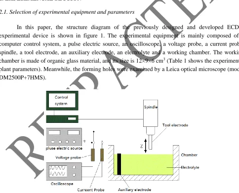
In this paper, the structure diagram of the previously designed and developed ECDM experimental device is shown in figure 1. The experimental equipment is mainly composed of a computer control system, a pulse electric source, an oscilloscope, a voltage probe, a current probe, spindle, a tool electrode, an auxiliary electrode, an electrolyte and a working chamber. The working chamber is made of organic glass material, and its size is 12×9×6 cm3 (Table 1 shows the experimental plant parameters). Meanwhile, the forming holes were examined by a Leica optical microscope (model: DM2500P+7HMS).
Figure 1. ECDM experimental device. The device consists mainly of the following parts: Control system; Pulsed electric source; Voltage probe; Oscilloscope; Current probe; Auxiliary electrode; Electrolyte; Chamber; Tool electrode.
[image:3.596.52.536.282.673.2]
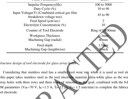
Table 1. ECDM experimental equipment plant parameters
Plant Parameters Values
Impulse Frequency(Hz) 100 to 5000
Duty Cycle (%) 10 to 90
Input Voltage(V) (Combined critical gas film
breakdown voltage test) 45 to 90
Feed Speed (µm/sec) 2
Electrolyte Concentration (%) 10
Counter of Tool Electrode Ring of Ø100mm
Workpiece Thickness 0.3mm
Machining Gap (radial) 60mm
Feed depth 1.5mm
Machining Gap (lengthwise) Touch
2.2. Structure design of tool electrode for glass array holes
Considering that stainless steel has a smaller tool wear rate when it is used as tool electrode [22], this paper takes stainless steel as the tool electrode material, ultra-white glass as the workpiece and array holes with three rows and three rows of structure as the goal, combined with the following WEDM parameters (VIW=70 V, IIC=1.5 A, TP=12 μs, FF= 1.5 mm/min) to complete the fabrication of
the tool electrode.
[image:4.596.48.544.152.743.2]
As shown in figure 2(a), when the tool cathode length is less than 10 mm and the pitch is less than 1mm, a large number of bubbles produced by chemical reaction pile up on the surface of cathode tools during the processing, so these bubbles not only increase the thickness of gas film, but also increase the breakdown voltage of the gas film correspondingly, which makes it difficult to break the gas film at a lower input voltage and makes the processing pause; When the input voltage is increased and reaches the breakdown voltage of the gas film, the bubbles produced in the machining gap are reduced, so the processing can continue (figure 2(b)); When the tool length is more than 10 mm, and the pitch is more than 1mm (figure 2(c)), the bubbles produced in the machining gap are fewer (able to machine).
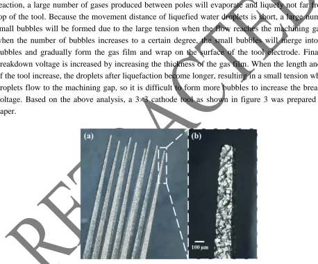
[image:5.596.56.514.244.624.2]Because when the length and pitch of the tool are short, coupled with the fast rate of chemical reaction, a large number of gases produced between poles will evaporate and liquefy not far from the top of the tool. Because the movement distance of liquefied water droplets is short, a large number of small bubbles will be formed due to the large tension when the flow reaches the machining gap,and when the number of bubbles increases to a certain degree, the small bubbles will merge into larger bubbles and gradually form the gas film and wrap on the surface of the tool electrode. Finally the breakdown voltage is increased by increasing the thickness of the gas film. When the length and pitch of the tool increase, the droplets after liquefaction become longer, resulting in a small tension when the droplets flow to the machining gap, so it is difficult to form more bubbles to increase the breakdown voltage. Based on the above analysis, a 3×3 cathode tool as shown in figure 3 was prepared in this paper.
Figure 3. 3×3 array stainless steel tool cathode with 15mm length and 1.5mm pitch. (The material of the cathode tool is stainless steel, and its processing mode is wire cutting. The corresponding process parameters are as follows: VIW=70V, IIC=1.5A, TP=12μs, FF= 1.5mm/min)
Compared with the neutral electrolyte, the alkaline solution OH- ion is a hydrophilic functional group. The OH- ion has a higher activity than the NO3- ion. Therefore, under the same conditions, the
K+ ion has a higher mobility than the Na+ ion [22], 10% KOH was selected as processing electrolyte [19].
3. RESULTS AND DISCUSSION
3.1. Selection of experimental parameters
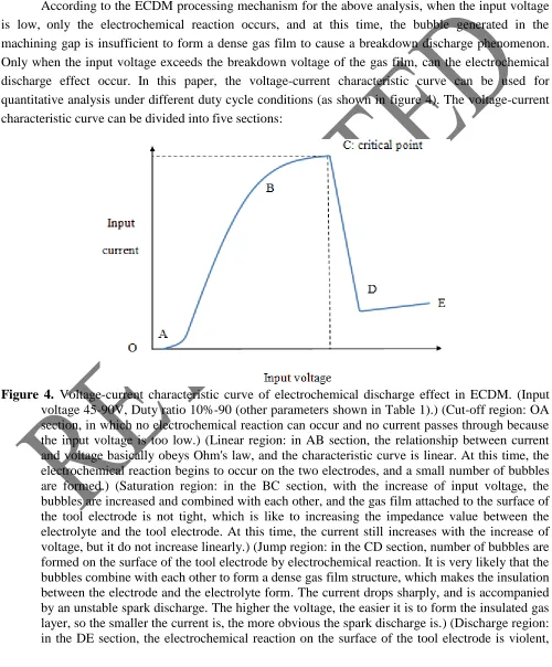
According to the ECDM processing mechanism for the above analysis, when the input voltage is low, only the electrochemical reaction occurs, and at this time, the bubble generated in the machining gap is insufficient to form a dense gas film to cause a breakdown discharge phenomenon. Only when the input voltage exceeds the breakdown voltage of the gas film, can the electrochemical discharge effect occur. In this paper, the voltage-current characteristic curve can be used for quantitative analysis under different duty cycle conditions (as shown in figure 4). The voltage-current characteristic curve can be divided into five sections:
[image:6.596.49.549.182.786.2]
the bubbles can be combined to form a stable gas film, and the spark discharge is carried out stably. The electrochemical discharge machining is carried out mainly in this range. Now, the higher the voltage, the greater the current, and the greater the spark discharge.)
Among these points, the C point is the critical point of transition from electrochemical reaction to spark discharge state. At this voltage, the spark discharge begins to occur, so the voltage where the C point is located is defined as the gas film breakdown voltage. Combined with the current-voltage characteristic curves of different duty cycles, the smaller the duty cycle is, the fewer the number of bubbles formed by the reaction is. Therefore, it is not easy to form an insulating gas film, resulting in an increase in the critical voltage. In this paper, the stable discharge voltage corresponding to a different duty cycle in 10%KOH solution is obtained by experiment (as shown in Table 2). Because the power supply energy below the 60% duty cycle is difficult to assure the machining of the array hole, so we only studied the case with a duty cycle of 60% or more.The above conclusion is consistent with the theory proposed by Cook and Tsutsumi et al. [29-34], in which the ECDM mechanism of glass materials in alkaline solution was studied.
Table 2. Input voltage values
Duty Cycle (%) Input Voltage(V)
60 70
70 61
80 50
90 48
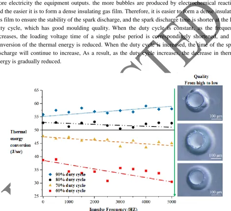
3.2. Process parameters influence on thermal energy
According to the energy calculation formula of a pulsed power supply, the heat energy generated under different process parameters can be obtained by energy conversion (such as formula 1).
I AI P
Thermal energyV I T (1)
thermal energy conversion. At the same time, when the thermal energy conversion is below 50J/sec, the array holes have higher quality. While when the thermal energy conversion is larger than 50J/sec, the array hole quality is poor, mainly in the form of cracks.
The results show that the seepage theoretical model established by the electrochemical method (U-I diagram) of Fascio et al. [38, 39] is consistent with the experimental results mentioned above. In other words, the pulsed electric source will have a charging process before the input voltage begins to load. When the frequency is the same, the smaller the duty cycle, the longer the charging time. The more electricity the equipment outputs. the more bubbles are produced by electrochemical reaction, and the easier it is to form a dense insulating gas film. Therefore, it is easier to form a dense insulating gas film to ensure the stability of the spark discharge, and the spark discharge time is shorter at the low duty cycle, which has good moulding quality. When the duty cycle is constant, as the frequency increases, the loading voltage time of a single pulse period is correspondingly shortened, and the conversion of the thermal energy is reduced. When the duty cycle is increased, the time of the spark discharge will continue to increase, As a result, as the duty cycle increases, the decrease in thermal energy is gradually reduced.
[image:8.596.61.531.194.624.2]
3.3. Process parameters influence on material removal rate
In the micro array holes machined by ECDM, the depth of the micro-holes increases with the prolongation of the processing time, which makes it difficult to cycle and drain the fresh electrolyte in the hole. Therefore, it will reduce the erosion effect at the bottom of the hole to a certain extent and produce a structure like the structure of the conical hole. In this paper, formula 2 can be used to describe the material removal rate (MRR) more accurately.
( / ).( /12).( 2 2 ( ))
t b t b
MRR t H D D DD (2)
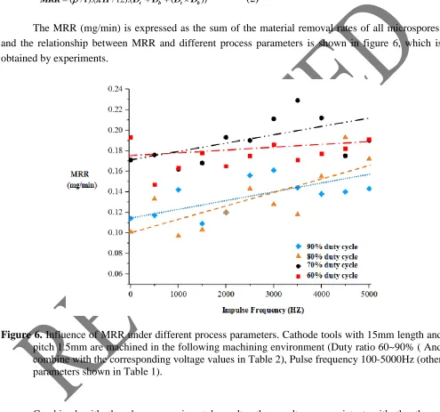
The MRR (mg/min) is expressed as the sum of the material removal rates of all microspores, and the relationship between MRR and different process parameters is shown in figure 6, which is obtained by experiments.
Figure 6. Influence of MRR under different process parameters. Cathode tools with 15mm length and pitch 1.5mm are machined in the following machining environment (Duty ratio 60~90% ( And combine with the corresponding voltage values in Table 2), Pulse frequency 100-5000Hz (other parameters shown in Table 1).
[image:9.596.49.544.193.656.2]
Because when the duty cycle is at 70%, the thermal energy conversion is much larger than 60%. When the thermal energy conversion is at 90%, the duty cycle is slightly higher than 80%. Combined with the thermal energy conversion relationship corresponding to different duty cycles proposed in figure 5, the MMR characteristics produced by different duty cycles in the DC environment are caused by thermal energy to a large extent.Although the input voltage at the 90% duty cycle is slightly higher than the input voltage at the 80% duty cycle, the spark discharge duration of the 90% duty cycle is longer,so it will act on more chemical corrosion and hot corrosion to improve MMR. In the 60%-70% duty cycle environment, similar MMR is caused mainly by the large input energy difference (that is, voltage).
In addition, the MRR achieves 0.23mg/min when the duty cycle is 70%, but compared with the 60% duty cycle, the quality of the holes under other frequency parameters is poor with cracks (see figure 7), consistent with the conclusion of Section 3.2 on the influence of different duty cycles on forming quality.
Figure 7. Quality of corrosion under different duty ratios ((a) micro-hole arrays with poor quality; (b) micro-hole arrays with high quality) (Figure 7(a) shows that cathode tools with 15mm length and pitch 1.5mm are machined in the following machining environment (Applied voltage 61V, Duty ratio 70%, Pulse frequency 3500Hz (other parameters shown in Table 1).) (Figure 7(b) shows that cathode tools with 15mm length and pitch 1.5mm are machined in the following machining environment (Applied voltage 70V, Duty ratio 60%, Pulse frequency 3500Hz (other parameters shown in Table 1).)
3.4. Process parameters influence on heat affected zone width
Figure 8. Influence of the HAZ under different process parameters. Cathode tools with a length of 15mm and a 1.5mm pitch are machined in the following machining environment (Duty ratio 60~90% ( Combine with the corresponding voltage values in Table 2), Pulse frequency 100-5000 Hz (other parameters shown in Table 1).
[image:11.596.123.523.71.423.2]
Figure 9. Quality of corrosion under different HAZs (micro-hole arrays with micro-cracks (a) and smooth profile (b)) (Figure 9(a) shows that cathode tools with 15mm length and pitch 1.5mm are machined in the following machining environment (Applied voltage 48V, Duty ratio 90%, Pulse frequency 4500Hz (other parameters shown in Table 1).) (Figure 9(b) shows that cathode tools with 15mm length and pitch 1.5mm are machined in the following machining environment (Applied voltage 61V, Duty ratio 70%, Pulse frequency 4500Hz (other parameters shown in Table 1).)
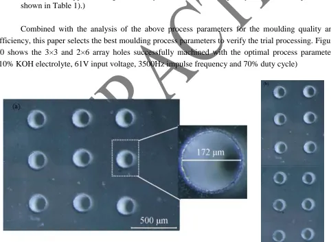
Combined with the analysis of the above process parameters for the moulding quality and efficiency, this paper selects the best moulding process parameters to verify the trial processing. Figure 10 shows the 3×3 and 2×6 array holes successfully machined with the optimal process parameters (10% KOH electrolyte, 61V input voltage, 3500Hz impulse frequency and 70% duty cycle)
[image:12.596.56.538.318.671.2]
4. CONCLUSIONS
To solve the problem of difficult machining of glass micro array holes in MEMS, a machining method of ECDM using an array tool cathode is proposed in this paper. First, the effect of different tool electrode lengths and pitches on the breakdown voltage of the gas film is analysed and the tool structure is optimized. Second, the heat energy conversion, MRR and HAZ width under different process parameters are studied by using the optimized tool structure. Finally, the high-quality machining of different array micro-holes is realized by using the reasonable machining parameters analysed above.
ACKNOWLEDGEMENTS
This research is funded by National Natural Science Foundation of China (NSFC) under grant number 51705392, the project of 2018 Shaanxi province key research and development projects under grant number 2018ZDXM-GY-077 and 2017 Shaanxi province special processing key laboratory open fund under grant number 2017SXTZKFJG04.
References
1. J. Arab, D.K. Mishra, H.K. Kannojia, P. Adhale and P. Dixit, J. Mater. Process. Tech., 271 (2019) 542.
2. F. Yang, G.W. Han, J. Yang, M. Zhang and J. Ning, Micromachines, 10 (2019) 1. 3. R. Wuthrich, V. Fascio, Int. J. Mach. Tool Manu., 45 (2005) 1095.
4. A. Sharma, V. Jain, D. Gupta, Mach. Sci. Technol., 23 (2019) 547.
5. M.P. Jahan, A. Perveen, A.M. Rumsey, Mach. Sci. Technol., 23 (2019) 264 6. A. Shar.ma, V. Jain, D. Gupta, Measurment, 128 (2018) 254.
7. Z. Wang, H.N. Li, T.B. Yu, Z.X. Wang and J. Zhao, Int. J. Mach. Tool Manu., 141 (2019) 59. 8. S. Madhu, M. Balasubramanian, Silicon. Neth., 10 (2018) 2453.
9. A. Nouhi, J.K. Spelt, M. Papini, Precis. Eng., 53 (2018) 151.
10.H.Z. Li, J. Wang, N. Kwok, T. Nguyen, G.H. Yeoh, J. Manuf. Process., 31 (2017) 156. 11.S. Madhu, M. Balasubramanian, Materialwiss Werkst., 48 (2017) 1146.
12.D. Peters, J. Drallmeier, D.A. Bristow, R.G. Landers and E. Kinzel, Mechatronics, 56 (2018) 188. 13.C. Gerhard, M. Stappenbeck, Appl. Sci. Basel., 8 (2018) 32.
14.Y. Re, R. Yoshizaki, N. Miyamoto, N. Sugita, Appl. Phys. Lett., 113 (2018) 6. 15.H. Kurafuji, Annals of CIRP, 16 (1968) 415.
16.V.K. Jain, P.M. Dixit, P.M. Pandey, Int. J. Mach. Tool Manu., 39 (1999) 165.
17.D.K. Mishra, A.K. Verma, J. Arab, D.Maria and P. Dixit, J. Micromech. Microeng., 29 (2019) 7. 18.V. Fascio, R. Wuthrich, H. Bleiler, Electro. Acta., 49 (2004) 3997.
19.B.Y. Jiang, S.H. Lan, T.K. Wil, Int. J. Precis. Eng. Man., 16 (2015) 5. 20.S.K. Chak, J. Mater. Sci. Mech. Eng.,2 (2015) 49.
21.Y. Zhang, Z.Y. Xu, D. Zhu, J. Xing, Int. J. Mach. Tool Manu., 92 (2015) 10. 22.N. Sabahi, M.R. Razfar, Int. J. Adv. Manuf. Technol., 95 (2018) 643.
23.B. Jiang, S. Lan, J. Ni, Z. Zhang, J. Mater. Process. Technol., 214 (2014) 892.
24.C.K. Yang, K.L. Wu, J.C. Jung, S.M.D. Lee and J.C. Lin, Int. J. Mach. Tool Manu., 51 (2011) 528. 25.D.J. Kim, Y. Ahn, S.H. Lee, Y.K. Kim, Int. J. Mach. Tool Manu., 46 (2006) 1064.
26.P.K. Gupta, A. Dvivedi, P. Kumar, Mater. Manuf. Processes., 31 (2016) 1740. 27.J. Wang, C. Fu, Z.X. Jia, J. Mater. Process. Tech., 252 (2017) 225.
28.S. Elhami, M.R. Razfar, Precis. Eng., 47 (2016) 424.
30.C. Tsutsumi, K. Okano, T. Suto, J. Mater. Process. Tech., 37 (1993) 639. 31.W.D. Wang, X.M. Kang, W.S. Zhao, Int. J. Electrochem. Sc., 14 (2019) 870. 32.K.R. Kolhekar, M. Sundaram, Precis. Eng., 53 (2018) 203.
33.F. Mehrabi, M. Farahnakian, S. Elhami, M.R. Razfar, J. Mater. Process. Tech., 255 (2018) 665. 34.P.K. Gupta, J. Electrochem. Soc., 165 (2018) E279.
35.V.K. Jain, P.M. Dixit, P.M. Pandey, Int. J. Mach. Tool Manu., 1 (1999) 23.
36.D.K. Mishra, A.K. Verma, J. Arab, D. Maria, and P. Dixit, J. Micromech. Microeng., 29 (2019) 7. 37.N. Sabahi, M.R. Razfar, Int. J. Adv. Manuf. Tech., 95 (2018) 643.
38.V.Fascio, R.Wüthrich, H.Bleuler, Electrochim. ACTA, 49 (2004) 3997.
39.N. Sabahi, M. Hajian, M.R. Razfar, Int. J. Adv. Manuf. Tech., 97 (2018) 1557. 40.M. Goud, A.K. Sharma, P. I. Mech. Eng. C-J. Mec., 231 (2017) 2417.
41.S. Saranya, A. Nair, A.R. Sankar, Microsyst. Technol., 23 (2017) 1453. 42.M. Goud, A.K. Sharma, J. Mech. Sci. Technol., 231 (2017) 1365.
43.Z.Y. Zhang, L. Huang, Y. J. Jiang, G. Liu, and X. Nie, Int. J. Adv. Manuf. Tech., 85 (2016) 2107. 44.A.B. Kamaraj, S.K. Jui, Z.C. Cai, M.M. Sundaram, Int. J. Adv. Manuf. Tech., 685 (2015) 2107. 45.B.Y. Jiang, S.H.Lan, J.Ni, Z.Y. Zhang, J. Mater. Process. Tech., 214 (2014) 892.