This is a repository copy of
A SysML Profile for Fault Trees : Linking Safety Models to
System Design
.
White Rose Research Online URL for this paper:
http://eprints.whiterose.ac.uk/152499/
Version: Accepted Version
Proceedings Paper:
Clegg, Kester Dean orcid.org/0000-0002-4484-3291, McDermid, John Alexander
orcid.org/0000-0003-4745-4272, Grigg, Alan et al. (1 more author) (2019) A SysML Profile
for Fault Trees : Linking Safety Models to System Design. In: Romanovsky, A and
Troubitsyna, E, (eds.) Computer Safety, Reliability, and Security:SAFECOMP 2019.
Lecture Notes in Computer Science . Springer Nature , pp. 85-93.
https://doi.org/10.1007/978-3-030-26601-1_6
[email protected] https://eprints.whiterose.ac.uk/
Reuse
Items deposited in White Rose Research Online are protected by copyright, with all rights reserved unless indicated otherwise. They may be downloaded and/or printed for private study, or other acts as permitted by national copyright laws. The publisher or other rights holders may allow further reproduction and re-use of the full text version. This is indicated by the licence information on the White Rose Research Online record for the item.
Takedown
If you consider content in White Rose Research Online to be in breach of UK law, please notify us by
safety models to system design
⋆Kester Clegg1
, Mole Li2
, David Stamp2
, Alan Grigg2
, and John McDermid1
1
University of York, United Kingdom, YO10 5DD
{kester.clegg,john.mcdermid}@york.ac.uk 2
Rolls-Royce (Controls) PLC, Derby, United Kingdom
{mole.li,alan.grigg,david.stamp}@rolls-royce.com
Abstract. Model Based Systems Engineering (MBSE) has encouraged
the use of a single systems model in languages such as SysML that fully specify the system and which form the basis of all development effort. However, using SysML models for safety analysis has been restricted by the lack of defined modelling standards for analytical techniques like Fault Tree Analysis (FTA). In lieu of such standards, the ENCASE project has formulated a simple SysML profile that captures the infor-mation required to represent fault trees and which enables the linkage of failure modes to other parts of the SysML model. Unlike traditional fault trees that can be difficult to validate against a system design, as-sociating failure modes with system functions and hardware components means that consistency checks between the two models are possible, and changes to the SysML design are easier to identify against the corre-sponding fault tree model. Common definitions of the system specifica-tion improves the quality of both safety analysis and assurance, and the alignment of the two models enables us to make the first steps towards the automatic translation of parts of the system design into fault trees.
Keywords: SysML·Fault Tree Analysis·Failure Modes
1
Introduction
Systems Modelling Language (SysML)3
is an extension of the Unified Modelling Language (UML) that focuses on systems modelling. SysML supports the speci-fication, analysis, design, verification and validation of a broad range of systems and systems-of-systems. However, ‘support’ in this sense is intended to mean a well-defined specification to describe the system, so that development and analy-sis can be performed using tools that take their data from a single model repos-itory. The approach is widely described as Model Based Systems Engineering (MBSE) and among its benefits is the hope it will remove most of the errors and
⋆Development supported by Rolls-Royce PLC and funded as part of Innovate UK’s
ENCASE project (Enabling Novel Controls and Advanced Sensors for Engines). 3
2 K. Clegg et al.
wasted development effort caused by conflicting sources of information. However there are also benefits for safety analysis, provided that the tool chains typically used in traditional critical systems development can be brought under the sin-gle SysML model. Unfortunately support for safety analysis has lagged behind the Object Modelling Group’s (OMG) SysML specification. This paper details our progress in the setting of Rolls-Royce’s UltraFan engine demonstrator devel-opment to provide SysML support to Fault Tree Analysis. The profile outlined here will form part of a wider safety and reliability profile similar to that recently proposed by the OMG (see below).
1.1 Background and previous work
To date, SysML has focused on supporting the requirements capture and func-tional side of systems engineering. However for safety critical systems, non-functional forms of analysis can be essential to argue that the system meets a required safety standard. Fault logic is typically modelled using a graphical representation of logic gates that traces the fault from base event to effect and which can contain additional information, such as failure rate, dispatch infor-mation and descriptive failure modes. A typical example is shown on the right hand side of Fig. 3 and the technique is defined in standards like IEC 61025 [4]. ENCASE’s initial starting point to model fault trees in SysML was an early paper from National Aeronautics and Space Administration (NASA)’s Jet Propul-sion Laboratory on fault protection modelling, which captured fault logic using activity diagrams [2]. We investigated using this approach but found issues with it. For example, there is no provision for AND gate representation in Activity Diagrams and the fault logic modelling at Rolls-Royce requires this to express the redundancy provided by a dual channel FADEC (Full Authority Digital En-gine Control)[5]. Secondly activity diagrams were never intended to model fault trees. Activities on Activity Diagrams become Call Behaviour Actions, which semantically seems at odds with fault logic, which is generally expressed as logic gates and failure modes. Although there are other potential diagram types none offer specific support for fault tree analysis and we decided we could best meet our needs by creating a bespoke diagram type.
chain, and discussions around how failure modes could be linked to functional specifications in the model. This is discussed in more detail in Section 2.
There is also recent work investigating the formal translation of Activity Di-agrams in UML / SysML to fault trees [3]. While this is a rigorous method, that entails a one to one correspondence between the two models, at this stage in the ENCASE project a more pragmatic approach is required due to the variety of ways engineers model activities. For example there are parts of Activity Di-agrams, such as Join Nodes, that are semantically ambiguous and can be used / interpreted differently by users which would make automated translation dif-ficult. More importantly there is a different approach to modelling between the system engineers (who model how things work) and the safety analysts (who model how things fail). The primary practical concern for the safety team was that the SysML fault tree models should be capable of modelling the system fault logic as it had been done historically and exporting it in a format where it could be analyzed by their existing tools such as FaultTree+ (part of Isograph’s Reliability Workbench suite). It is relatively simple to model the fault logic to the point at which the base events are specified, the base event details (failure rates from the FMEA / FMECA, exposure periods, etc) can then be extracted from the Failure Modes and Effects Summary (FMES) database (see [6]) using spreadsheet macros and exported as a workbook to be imported by FaultTree+. This gives a low risk migration strategy from the existing approach to that of-fered by MBSE, even though as we discuss in Section 2.1 changing the way fault logic is currently modelled will be necessary to maximize the benefits of MBSE. Rolls-Royce currently use failure modes as human readable placeholders or descriptions within the fault tree that describe the fault logic gate below them (see right hand side of Fig. 3). Their primary purpose is to help safety an-alysts understand and keep track of the fault logic of the system, which can be extremely large (i.e. hundreds of pages) and complex. By associating them with specific functional behavior modelled as activities in SysML, the system engineers gain visibility of failure modes while modelling system functions and can view the associated fault logic. However, this linkage (through failure mode linked elements) also gives the future possibilty of validating fault trees against a system function or associated hardware when changes to the SysML model are made. See Fig. 1 and its description below for more details.
2
A Bespoke Fault Tree Profile for SysML
4 K. Clegg et al.
[image:5.612.134.482.162.417.2]UML 2.5 and provides additional extensions to aid Fault Tree analysis in UML and SysML [1].
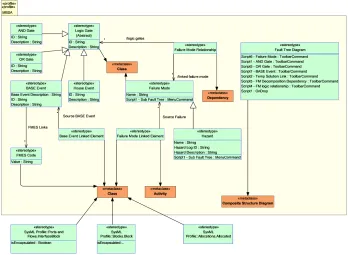
Fig. 1.Meta model of the proposed Fault Tree Profile, which will form part of a larger
MBSA profile. The Fault Tree Diagram scripts are not part of the profile but serve to recreate a familiar user interface for safety analysts in PTC Integrity Modeller (PTC IM).
The meta-model of our Fault Tree profile is shown in Fig. 1. In software engineering, a meta-model is a mechanism for representing a well-formed formula or the abstract syntax of a modelling language [7]. The definitions and semantics of each concept of the meta-model are introduced as follows:
Logic Gate Abstract meta-class (i.e. no concrete entity in the SysML model) and im-plemented as a stereotype (i.e. an applied extension) that generalises the common attributes ofAND Gate, OR Gate, Base Event andHouse Event. As it is a general modelling concept, itsID tag definition specifies the unique reference for gates in the fault tree.Description allows users to specify tex-tual information to assist identification.
Base Event Concrete meta-class that represents lowest level of a fault tree diagram. Meta-modelling mechanism similar toAND &OR Gates. Links to hardware components via Base Event Linked Element meta-class. The Base Event
FMES code allows scripts to retrieve its failure rates, probabilities, exposure periods and dispatch information from the FMES database.
House Event Concrete meta-class similar to abase eventexcept that it serves as a Boolean flag or switch to isolate parts of the fault tree under a particular analysis (i.e. it’s a “normal event” expected to happen, not a “failure”).
Failure Mode Concrete meta-class that represents a descriptive placeholder used to de-scribe the fault logic at that point in the fault tree. The meta-modelling mechanism is similar to the logic gates.
Failure Mode Relationship Concrete meta-class that defines the relationship betweenLogic Gate such asAND Gate,OR Gate,Base Event,House EventandFailure Mode. Imple-mented as a stereotyped UML: Dependency meta-class to representFailure Mode Relationship as a first-class entity. Two reference-type tag definitions
Logic GatesandLinked Failure Mode connectLogic GateandFailure Mode.
Hazard Concrete meta-class that represents the top level Hazard in a fault tree. We intend this class to be part of wider profile used to capture Functional Hazard Analysis (see ARP4761 [6]). It generalisesFailure Modeand extends the tag definitionsHazard Log ID and Hazard Description.
Base Event Linked Element Meta-class that links one or more Base Event to system hardware com-ponents defined in SysML Internal Block Diagrams and Block Definition Diagrams. Not implemented as a first-class entity, therefore cannot exist by itself. The stereotype applies to UML: Class (SysML Block is a stereo-typed UML: Class) in order to increase safety visibility for systems engineers. In addition, it has a reference type tag definitionSource Base Event to connect stereotyped system hardware component andBase Event.
Failure Mode Linked Element Meta-class that links one or moreFailure Mode to abstract hardware spec-ifications defined in SysML Internal Block Diagrams and Block Definition Diagrams, and system features and functions in SysML Activity Diagrams. The meta-modelling mechanism is similar toBase Event Linked Element.
FMES Code Concrete meta-class that represents FMES Base Event codes. Linked with zero or moreBase Event via reference tag definition FMES Links of Base Event. The Value tag is a unique identifier in the FMES database.
Fault Tree Diagram A bespoke diagram type to model fault logic using fault trees. In order to make the current SysML modelling tool (PTC’s Integrity Modeler) a user friendly interface for safety analysts accustomed to working with Isograph’s FaultTree+, user defined scripts provide some UI behaviour (more details in Section 2.1). The extension mechanism is the same as the SysML Internal Block Diagram that extends UML Composite Structure Diagram.
2.1 Implementation
6 K. Clegg et al.
Fig. 2.Assigning failure modes (RHS dialogue box) from the fault tree level ‘Channel
A LP overspeed protection ineffective” (LHS tree hierarchy) via a Failure Mode Linked Element on the Activity ‘Check for LP Shaft Overspeed Event’ (RHS top panel).
toolbars and actions on a bespoke diagram type. A typical screenshot is shown in Fig. 2. This has one “level” in a branch of the fault tree defined as an AND gate, with failure modes describing the junction point above and below. Double clicking on either of the failure modes below will take the user to the next level below or create a new level (defined as a failure mode) in the tree. The hierarchical structure (i.e. the fault logic) of the fault tree is shown in the left hand panel. At the lowest level of this branch in the fault tree are the base events with their FMES codes. Scripts will be able to “walk” the fault tree hierarchy down to the base events and export this to a spreadsheet within the FMES database, where macros can combine it with information linked to the Base Event FMES codes to be imported into FaultTree+ for analysis.
The most striking difference between our profile and the initial safety profile published by the working group for the OMG [1] is our decision not to bring the FMEA information directly into the SysML model. Instead, the base events keep their unique identifier that can allow that information to be extracted from the FMES database. The reason for this is that the FMES is quite large (>3K rows)
Fig. 3.Lower level of H01 fault tree showing base events with FMES identifiers. The LHS is our profile as rendered by PTC IM, the RHS shows the output from FaultTree+.
to maintenance intervals), a case can be made for linking them to derived safety requirements kept elsewhere in the model and we will be issuing an updated profile at a later date to reflect this, but otherwise all that is needed is the FMES code. The FMES is a summary of the FMECA database (>25K rows),
and it is this database that is changed and maintained with the latest failure rates. Therefore it is easiest if a new analysis is to be run to extract the summary failure rate data directly from the databases, while keeping the fault logic and knowledge of the failure modes within the SysML model. This is in keeping with our belief that the SysML model represents a knowledge repository, whereas the FMECA and FMES databases are designed to handle, import and export large amounts of data efficiently and are able to interface with a wide range of tools. Fig. 3 shows the implementation of our profile in PTC Integrity Modeler and compares two fault tree structures. Removing the FMES data (which is not used by the safety analysts when modelling the fault logic - it is added by FaultTree+ by combining the failure rates of base events) gives a much cleaner interface, with greater opportunity to add explicit descriptions within the failure modes that can then be linked outwards to activities or hardware components.
2.2 Alignment of safety and system models
8 K. Clegg et al.
against a hazard, thus an analysis for a dual channel control system might query why the mitigation provided by the redundant channel has failed in addition to the channel in control. Contrast this with the system engineer’s perspective, which is to consider an engine protection feature in its abstract specification first, then to consider its implementation and finally how it is implemented on a respective channel. In MBSE, fault logic models should follow where possible the functional breakdown of the system engineers. Fault trees are often “richer” models that can include physical or external factors outside the system’s func-tional specification but required to understand how that function could fail. To maximise benefits such as being able to cross-check models for inconsistencies, or auto-generate fault trees from parts of the model, the profile must allow failure modes to be associated with and traceable to specific parts of the SysML model.
3
Conclusions
The use of MBSE may lower development costs but it is not proven that it results in safer systems. Such an approach has to ensure the single model does not contain any flawed logic that is then replicated throughout different forms of safety analysis, as the analyses will all use the same source data. Losing the additional assurance of an independent model of the system’s fault logic needs to be justified by demonstrating the value of validation and being able to identify changes between models during development. Bringing safety and system models together to share their definition of system artifacts improves the quality of safety analysis, helps assure compliance and moves us a step closer to auto-generating parts of the fault tree model from the system design.
References
1. Biggs, G., Juknevicius, T., Armonas, A., Post, K.: Integrating Safety and Reliabil-ity Analysis into MBSE: overview of the new proposed OMG standard. INCOSE International Symposium28, 1322–1336 (07 2018). https://doi.org/10.1002/j.2334-5837.2018.00551.x
2. Day, J., Murray, A., Meakin, P.: Toward a model-based approach to flight system fault protection. In: Aerospace Conference, 2012 IEEE. pp. 1–17. IEEE (2012) 3. Dickerson, C.E., Roslan, R., Ji, S.: A Formal Transformation Method for
Auto-mated Fault Tree Generation From a UML Activity Model. IEEE Transactions on Reliability67(3), 1219–1236 (Sep 2018). https://doi.org/10.1109/TR.2018.2849013 4. IEC 61025: Fault tree analysis (FTA). Standard, International Electrotechnical
Commission, Geneva, CH (August 2006)
5. Li, M., Batmaz, F., Guan, L., Grigg, A., Ingham, M., Bull, P.: Model-based systems engineering with requirements variability for embedded real-time systems. In: 2015 IEEE International Model-Driven Requirements Engineering Workshop (MoDRE). pp. 1–10 (Aug 2015). https://doi.org/10.1109/MoDRE.2015.7343874
6. Guidelines and methods for conducting the safety assessment process on civil air-borne systems and equipment ARP4761. Standard, SAE International, Warrendale, PA, USA (1996-12-01)