Return current and proton emission from short pulse laser interactions
with wire targets
a…F. N. Beg,1,2,b)M. S. Wei,1E. L. Clark,1,3A. E. Dangor,1R. G. Evans,1,3P. Gibbon,4 A. Gopal,1K. L. Lancaster,1,4K. W. D. Ledingham,5P. McKenna,5P. A. Norreys,6 M. Tatarakis,1,7M. Zepf,8and K. Krushelnick1
1The Blackett Laboratory, Imperial College, London SW7 2BZ, United Kingdom
2Department of Mechanical and Aerospace Engineering, University of California, San Diego 92093-0411 3AWE plc, Aldermaston, Reading RG 4PR, United Kingdom
4Forschungszentrum, Ju¨lich GmbH, ZAM, D-52425 Ju¨lich, Germany
5Department of Physics, University of Strathclyde, Glasgow G4 0NG, United Kingdom 6Rutherford Appleton Laboratory, Chilton, Oxon, OX11 0QX, United Kingdom
7Laboratory of Optoelectronics, Department of Electronics, Technological Educational Institute of Crete,
Romanou 3, Crete, Greece
8Department of Physics, The Queens University, Belfast BT7 1NN, United Kingdom
共Received 27 October 2003; accepted 20 February 2004; published online 23 April 2004兲
Results are presented from laser–plasma interaction experiments using the VULCAN laser at the Rutherford Appleton Laboratory. Wire targets were used to elucidate the role of the return currents generated by the relativistic electron beam leaving the target at laser intensities up to 5
⫻1019W cm⫺2. For some shots an additional wire or a foil was placed near the target wire. In other shots, a foil was used as the target with a wire behind. Three main observations were made: 共i兲 Z-pinch behavior in the wires due to the return currents,共ii兲optical transition radiation共OTR兲at the second harmonic of the laser, and 共iii兲 proton emission. The OTR and the proton emission were observed from both the primary wire target and the adjacent wire. The OTR emission is associated with electron bunches at twice the laser frequency due to ponderomotive JÃB acceleration by the laser. The proton emission from the adjacent target was likely due to field emission of electrons by the large potential produced from charging of the primary wire target. The observations agree with simulations using the three-dimensional tree code PEPC and the two-and-one-half-dimensional particle-in-cell code OSIRIS. © 2004 American Institute of Physics. 关DOI: 10.1063/1.1704643兴
I. INTRODUCTION
One of the important characteristics of short pulse high intensity laser–solid interactions is the generation of ener-getic beams of electrons,1protons2and gamma rays,3which result from the very efficient conversion of laser energy into hot electrons. Since the electrons in the electric field of the laser have relativistic quiver motions, the temperature of the hot electron distribution of the plasma produced at such ex-treme intensities can be very high. There is evidence of a transition between resonance absorption 共both Brunel-type and classical兲 and JÃB ponderomotive absorption when
vosc/c approaches unity for relatively steep density
scale-length plasmas (Ln⬃1 – 2m).4 The intensity scaling of hot electron temperature Th changes from Th
⬇0.1 (I18 2
)1/3MeV共Ref. 3兲to the ponderomotive scaling,4
Th⬇0.3 (I182)1/2MeV共where I18is the intensity in units of 1018W/cm2 and is the wavelength of the laser light in microns兲. It appears that both processes can occur during the interaction, especially for oblique incidence p-polarized interactions.5 In any case, a large number of hot electrons (1013– 1014) having an average energy of the order of 1–2
MeV can be generated as intensities exceed 1019W cm⫺2, which therefore leads to the production of significant return currents in the plasma.
There are, in general, two types of return currents pro-duced in such experiments. One occurs as the beam of hot electrons penetrates into the plasma. This is just a conse-quence of the electric field induced by the temporal variation of the magnetic field produced by the electron beam. Indeed for large currents of relativistic electrons this beam requires a large neutralizing return current of cold plasma electrons moving in the opposite direction in order for the hot beam to propagate 共i.e., for beams with currents greater than the Al-fve´n limit JA⬃17␥kA). These return currents can cause
Ohmic heating in regions of the plasma interior共because the colder electrons in the return current are more collisional兲. This has been discussed by several authors.6 –9
The other related source of return current is due to the population of very energetic electrons which ‘‘escape’’ the plasma and which create a large electrostatic potential on or near the target due to charge separation between these elec-trons and the heavier ions. If the return current can respond quickly to this charge imbalance, more hot electrons can con-sequently be emitted from the plasma. In general, the number of the electrons which can escape in this way is much less than those in the neutralized electron beam which penetrates
a兲Paper KI2 3, Bull. Am. Phys. Soc. 48, 170共2003兲.
b兲Invited speaker. Author to whom correspondence should be addressed.
Electronic mail: [email protected]
2806
of phenomena can be observed because of the generation of return currents in response to the resulting large scale electric fields.
One such phenomenon is the production of energetic proton beams,2,10which are of considerable interest due to a number of potentially important applications such as table-top accelerators, the production of medical radioisotable-topes and for fast ignition in inertial confinement fusion. The main re-quirement for these applications is that the beam should be highly collimated with little energy spread. It has been observed11,12that variation in the target geometry and mate-rial significantly affects the properties of the electron beam. In this paper, the consequence of the return current and measurements of proton generation from the wire targets in-teracting with short pulse high intensity laser are presented. Optical and x-ray emission from the wire due to Ohmic heat-ing caused by the return current were observed and an m
⫽0 instability was found to develop in the wires. The proton emission was found to be in the form of an almost uniform double disk perpendicular to the wire at the interaction re-gion. Another important observation was the second har-monic emission from the primary target共wire or foil兲as well as the additional nearby secondary wire or foil wire. The structure of emitted energetic protons was also found to be significantly altered when the additional secondary wire was introduced. Some aspects of the interaction were modeled using a particle-in-cell共PIC兲code13 and a new type of grid-less tree code.14
II. EXPERIMENTAL SETUP
The experiments were performed on the VULCAN Nd: glass laser system15using the CPA共chirped pulse amplifica-tion兲beam. The laser wavelength was 1.054 m, the pulse length varied between 0.9 and 1.3 psec and the energy inci-dent on target was between 60 and 100 J. The laser was focused with an off-axis parabolic mirror 共focal length 60 cm兲to a spot size of the order of 15m diameter. The targets used were共a兲a single wire,共b兲two parallel wires with only one illuminated by the laser and共c兲a foil target with a wire behind the foil. The wires were 20 m diameter hard tem-pered copper with a length of 3 or 5 mm attached to a 3 mm diameter grounded stalk. Gold and glass wires were also used. The foil was 50m thick, 50⫻50 mm2aluminum. The distance between the target wire or foil and the second wire was of the order of 300m. For the wire target, the laser was focused either close to the free end of the wire or a few 100 m from the end. For the foil target, the laser was at 45° to the normal.
The target was probed perpendicularly to the wire 共or parallel to the plane of the foil兲using shadowgraphy with a picosecond, frequency doubled 共527 nm兲 probe beam. An optical four-frame camera, based on gated image intensifiers
connected to charged coupled detectors 共CCD兲was used to image emission from the target共wire or foil兲and the nearby wire. The framing time was 1 ns. The first frame being timed to be coincident with the laser. Notch, broad band and inter-ference filters were used to identify the likely frequency of the optical emission. The angular emission and energy dis-tribution of protons was measured using stacks of radiochro-mic film 共RCF兲interleaved with CR39 plastic nuclear track detectors. The stopping power of protons in RCF and CR39 is well known—so that at a particular layer in the stack the energy of protons producing the signal was easily determined.16The RCF in the stack is sensitive to all ioniz-ing radiation whereas the CR39 detectors are sensitive only to ions with energy⬎100 keV/nucleon. Heavy ions and low energy protons are stopped in the first RCF layer 共110 m thick兲. The detector stack was 5⫻5 cm2and was positioned at a distance of 20–50 mm from the target. An x-ray pinhole camera was also used to measure the time integrated x-ray emission. The full details of the experimental setup are given in Refs. 17 and 18.
III. EXPERIMENTAL RESULTS
A. Return current in wires
The optical images from a single wire target obtained with the gated optical camera are shown in Fig. 1. There were two regions of optical emission; 共i兲 a region of large emission localized at the laser spot on the wire and,共ii兲 emis-sion along the wire connected to the ground. Clearly, there is a radial expansion of the wire, which is likely due to the Ohmic heating by an electric current. This current is gener-ated in the wire by the charge imbalance cregener-ated by hot elec-trons escaping the target. The expansion velocity of the wire 共average 5⫻105m/s) observed during these experiments is similar to that routinely observed in single wire Z-pinch dis-charge experiments with current in the range of 0.1–1 MA.19 The current can be estimated from a simple energy bal-ance equation,20 f IA⫽(JH/e)kThot, where f is the fraction
of the energy absorbed into hot electrons, I is the intensity of the laser, A is the area of the laser spot and Thot the hot
electron temperature which is given by the laser ponderomo-tive energy 关eTH⬇mec2(␥⫺1), where ␥ is the relativistic factor of the electrons oscillating in the laser electric field兴. A hot electron current of approximately 4 MegaAmps can be calculated in our experiment ( f⬃10%, I⬃5
⫻1019W cm⫺2, a spot size ⬃15 m, and T
hot⬃2 MeV).
[image:2.612.359.518.55.145.2]tance L of the wire and the hot electron temperature TH, given by the equation: LI/t⬃kBTH/e. The estimated re-turn current rise time is a few 10’s of psecs.
Heating due to the return current is also evident from the time integrated x-ray pinhole images. Figure 2 shows sau-sage m⫽0 magnetohydrodynamic共MHD兲instability similar to that observed in a Z-pinch discharge. The curved emission regions in the x-ray image are likely caused by the motion of the plasma after the current has ended and after such insta-bilities have stopped growing. The average periodicity of the instability was 110m共the largest and shortest wavelengths being 270 and 40 m, respectively兲. This wavelength is in rough agreement with the calculated wavelength based on the model by Haines.21 The MHD linear growth time of the instability, given by the Alfve´n wave transit time across the pinch radius, is of the order of 0.1–1 ns. This is much longer than the laser pulse duration and the rise time of the current estimated above.
Figure 3 shows the images of optical emission when a second wire was placed nearby the target wire. A narrow band pass filter at 2was used. Radial expansion is observed in both wires which is the clear evidence there are induced return currents in both wires. Further evidence for this is the
m⫽0 instabilities seen in both wires in the x-ray pinhole photographs. It is interesting to note that emission is less intense and expansion is slower in the target wire. This indi-cates the current in the nearby adjacent wire is larger. It is important to note that the adjacent wire was positioned so that it was unlikely that is would be irradiated by the laser.
In order to eliminate possibility of any scattered laser light reaching the second wire, a 50m thick, 5 mm⫻5 mm
aluminum foil was used as the target and a wire placed be-hind the foil at a distance of 250 m. The gated imager was positioned to view the rear surface of the foil and the wire, as shown in Fig. 4共b兲, through a 2interference filter. Intense emission at 2can be seen from the rear surface of the foil target and emission from the wire behind the foil is also evident 关see Fig. 4共a兲兴. This emission is due to intense field emission from the wire—which subsequently provides most of the return current for the hot electrons, which escape dur-ing the interaction.
[image:3.612.382.494.53.131.2]The observations show that in all three target configurations—single wire, two adjacent wires and foil with wire behind—there is a significant amount of second har-monic emission. Figure 5 shows for the two wire configura-tion the emission is most intense from around the focal spot on the target wire and from a localized region at the same height in the nearby second wire共the laser is in the horizon-tal plane兲. In the foil/wire target configuration共Fig. 4兲the 2 emission is most intense from the back of the foil. We be-lieve that this emission is due to the coherent optical transi-tion radiatransi-tion, which is generated when high energy elec-trons cross the interface between media with different dielectric properties.22 At the focal spot on the target the electron beam is produced by the ponderomotive JÃB force of the laser,23and at the secondary wire, the beam is caused by electron acceleration in the electric field between the tar-get and the nearby wire. The emission is coherent and is at 2 since the electrons are generated at twice the laser frequency.24,25
[image:3.612.122.231.54.188.2]FIG. 2. Time integrated x-ray pinhole photograph (h⬎400 eV) of共a兲a single wire and共b兲two wire configuration. The laser focal spot on the wire is out of the field of view.
[image:3.612.363.515.568.671.2]FIG. 3. A sequence of optical framing camera photographs with a second wire placed near the target wire. The laser was focused on the wire on the right.
FIG. 4.共a兲The prompt optical gated image with the laser focused at the foil target with a wire placed behind.共b兲Sketch showing the rear of the foil and the wire as viewed by the camera.
[image:3.612.93.257.642.722.2]These results represent the first observations of accelera-tion of relativistic electrons in the form of bunches through the vacuum and also emission at 2 from wire or foil共not irradiated by the laser兲in close proximity of the wire target.
B. Proton emission from wire targets
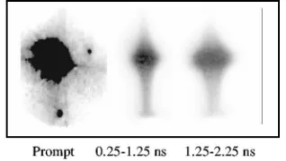
With a wire target, the structure of the proton emission is significantly different from that observed with a planar foil target. The proton emission from a foil target is in the form of a cone aligned approximately along the normal to the foil in both the forward and blow-off directions.4 With a wire target the proton emission is in the form of an expanding disc perpendicular to the wire and centered at the focused spot of the laser on the wire. This can be seen in Fig. 6, which shows typical scanned RCF and CR39 images obtained from stacks positioned in the forward and blow-off directions. All the images show a horizontal strip which is uniform along the width of each stack, i.e., over⬃100° angle around the wire. Note that the there is a split strip in the first RCF image 关Figs. 6共a兲and 6共d兲兴, which becomes a single strip at higher energies. The maximum energy in the strip is about 9 MeV 关Fig. 6共c兲兴 and subtends an angle of 3.6°. There is also a diffuse proton pattern关Fig. 6共c兲兴. Here the laser was focused on the wire within 30 m of the free end of the wire. The diffused structure has an angle width 22° and is at 45° to the laser beam direction. This is likely due to the fast electron
beam, which creates space charge that accelerates protons away from the target. When the laser is focused near the stack, the diffuse pattern is larger and more complicated as seen in Figs. 6共d兲and 6共e兲, which are from the stack in the blow-off direction.
When an additional wire is placed adjacent to the target wire, proton emission is observed from both wires共Fig. 7兲. As in the single wire case, the emission is in the form of the disk from each wire. Each strip is split at low energy 关Fig. 7共a兲兴and has an angular width of about 4°. The separation between the strips is due to the tilt of the two wires. The CR39 image formed from protons with energies from 3 to 9 MeV has a very complex pattern, which is completely dif-ferent from that in the single wire case. This is also the case for the emission in the blow-off direction.
IV. SIMULATIONS
Single wire experiments were simulated using PEPC, a new gridless, electrostatic particle code which uses a parallel tree algorithm to compute interparticle potentials and forces directly in a time O(N log N). Technical details of this code are given in Ref. 26, and a more extensive account of the simulations will be published elsewhere.16Just as with a PIC code, the physical parameter space, which a tree code can
共 兲
[image:4.612.57.294.54.115.2]single wire targets.共a兲First RCF image;共b兲second RCF layer;共c兲CR39 in the deep layer of the stack positioned in the forward direction;共d兲first RCF layer behind a 12m Al filter; and共e兲CR39 in the deep layer of the stack positioned in the blow-off direction.
[image:4.612.345.529.54.155.2]FIG. 7. 共Color兲RCF and CR39 images showing the proton emission from two wire targets.
[image:4.612.100.515.526.732.2]handle, is also limited by computational cost, albeit for dif-ferent reasons. For the time being, we therefore consider a 1/10-scale wire model with radius rw⫽1m and length 10 m. This is suspended in free space with open boundary conditions: particles are allowed to fly as far as they wish from the interaction region without artificial recycling. The wire density is initially uniform with ne⫽ni⫽4nc, where nc is the critical density. A total of 1.4⫻106 electrons and ions were used, the ions having an atomic number Z⫽1 and mass
mi/me⫽1836.
The laser is modeled as a ponderomotive standing wave potential共with both dc and oscillating components兲, initially focused near the midpoint of the wire with a 0.5 m full width at half maximum 共FWHM兲sin2 radial profile. The in-tensity is ramped up over 10 fs to a peak value of 25
⫻1019W cm⫺2, held constant for 200 fs and then switched off. A simple tracking algorithm is used to follow the critical density surface inwards as it buckles under the laser pressure. The pulse duration is therefore restricted to values below 2 rw/uh, where uh is the usual hole-boring velocity,
14,24
in this case 0.05c.
That the target becomes highly positively charged as a
result of the laser irradiation is supported by the simulation results in Fig. 8, which show slices of the target potential in planes along the wire and laser axes, respectively, at a time near the end of the pulse. Apart from the region surrounding the hole, the target is uniformly charged to a potential of around 1 MV, a value consistent with the estimate above. The full spatial extent of the potential ‘‘envelope’’ is much larger than implied by Fig. 8共b兲, and grows with time; at this point共160 fs兲, the electron cloud seen in the phase-space plot Fig. 9 fills a region 30 times larger than the initial wire radius.
[image:5.612.111.503.50.449.2]the experiments and are limited by the computational cost. In the simulations the electrons in the foil and in the wire are treated as distinct species and may be plotted separately.
Figure 10 shows some of the simulation results. In Fig. 10共a兲we plot the longitudinal phase space共p1 vs x1兲of the ‘‘foil’’ electrons at 120 fsec. The electrons in the foil target
wire are accelerated towards the foil and reach energies of more than 4 MeV共␥⫽8兲. The lines drawn in Fig. 10共b兲 em-phasize the bunching of the electrons leaving the wire and showing a similar periodicity to the laser accelerated elec-trons. This should give rise to the emission of second har-monic 共green兲light from the nonirradiated wire due to opti-cal transition radiation. Indeed this is in excellent agreement with the experimental observations where well-localized sec-ond harmonic emission is observed from the secsec-ondary wire. The observations indicate that there is a significant com-ponent of proton emission, which is symmetric around the wires due to the fast electrons moving around the wire. These electrons form an electrostatic sheath around the wire resulting in proton emission in the form of a disk.
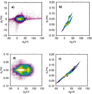
Support for this proposition is also found in the 3D tree code simulation described earlier, where two types of ion emission—beam-like and disc-like—are seen. The first of these is produced along the laser axis via the ponderomotive shock: monitoring the time-development of the longitudinal ion phase space ( pxvs x兲shows that in this case, emission is dominated by front-side ions, which also exit the wire with more energy than the rear-side, sheath-accelerated ions— Figs. 9共b兲 and 9共c兲. The maximum energy in this forward-directed beamlet is 共probably coincidentally兲 also 9 MeV, although the main component is at around 3 MeV.
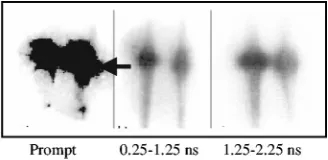
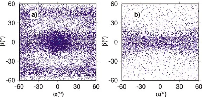
The far-field emission pattern corresponding to the RCF and CR39 images is reconstructed in Fig. 11, which for sta-tistical reasons, displays the angular distribution of the transverse/longitudinal momenta f (␣,), where ␣
⫽arctan(py/px), ⫽arctan(pz/px), rather than the particle count on a virtual collector plate. In both forward and back-ward directions, we observe the same double-stripe structure seen in Fig. 6, albeit at somewhat lower energies 共0.5–1.5 FIG. 10. 共Color兲The longitudinal phase space of electrons from共a兲a foil
[image:6.612.101.513.540.739.2]target at 120 fs and共b兲secondary wire target at 180 fs using 2-1/2 D PIC simulations with OSIRIS code.
MeV兲. This structure actually develops further after the laser has been turned off, suggesting that it is a return current effect, which again depends on the absolute amount of hot electron charge initially stripped from the wire by the laser. The details of this disc-like emission—in particular whether these features persist as the laser and target parameters are scaled up—will be addressed by future simulations.
The presence of secondary wire or foil in the vicinity of these wire targets affects the proton emission significantly. The proton emission from two sources is consistent with OTR observations from the primary target wire and addi-tional secondary wire. The physical mechanism for OTR and proton emission from the secondary wire or foil is as fol-lows: the relativistic electrons produced in the interaction region are strongly bunched at 2and when they escape the wire, they leave a large positive charge on the target wire. This creates a large potential between the target wire and an additional wire or foil. As a result electrons are emitted due to field emission and the space charge field created can ac-celerate the protons. Further numerical work is underway to understand the complex physics involving the target wire and the additional wire.
V. SUMMARY AND CONCLUSIONS
A series of experiments was performed to understand the effect of return current heating and proton generation from wire targets. The Ohmic heating of the wire targets was ob-served. This resulted in the onset of the m⫽0 instability 共similar to that routinely observed in Z-pinch experiments兲. A significant change in the physics of interaction was ob-served when an additional wire or foil was used. The optical transition radiation from a secondary wire or foil due to bunches of electrons accelerated by JÃB force of the laser could be observed. A significant change in the spatial struc-ture of the proton beam was also measured.
Finally, from these experiments it seems possible to en-hance the power levels of the x-ray emission from laser-driven Z pinches using multiple wire arrays and X-pinch configurations—similar to present Z-pinch wire array re-search which uses pulse-power drivers.27 With a very fast rising current such as that in the experiments described here it may be possible to have more uniform plasmas and con-sequently very high x-ray powers. In addition, experiments on wire array heating with fast rising current, presently not possible with present pulsed power technology, will provide a test-bench for numerical codes to study the dynamics of wire arrays.
ACKNOWLEDGMENTS
The authors acknowledge the assistance of the staff of the Central Laser Facility of the Rutherford Appleton Labo-ratory in the execution of this work as well as the support of the UK Engineering and Physical Sciences Research Council 共EPSRC兲. We would like to thank Professor M. G. Haines for useful discussions.
We gratefully acknowledge the OSIRIS consortium which consists of UCLA/IST共Portugal兲/USC for the use of
OSIRIS. P.G. acknowledges access to computing resources on the Juelich IBM p690⫹ cluster, awarded under project number JZAM04.
1
M. Tatarakis, J. R. Davies, P. Lee, P. A. Norreys, N. G. Kassapakis, F. N. Beg, A. R. Bell, M. G. Haines, and A. E. Dangor, Phys. Rev. Lett. 81, 999 共1998兲; M. Borghesi, A. J. Mackinnon, A. R. Bell, G. Malka, C. Vickers, O. Willi, J. R. Davies, A. Pukhov, and J. Meyer-ter-Vehn, ibid. 83, 4309 共1999兲; L. Gremillet, F. Amiranoff, S. D. Baton, J.-C. Gauthier, M. Koenig, E. Martinolli, F. Pisani, G. Bonnaud, C. Lebourg, C. Rousseaux, C. Toupin, A. Antonicci, D. Batani, A. Bernardinello, T. Hall, D. Scott, P. Norreys, H. Bandulet, and H. Pe´pin, ibid. 83, 5015共1999兲.
2A. P. Fews, P. A. Norreys, F. N. Beg, A. R. Bell, A. E. Dangor, C. N.
Danson, P. Lee, and S. J. Rose, Phys. Rev. Lett. 73, 1801共1994兲; E. L. Clark, K. Krushelnick, J. R. Davies, M. Zepf, M. Tatarakis, F. N. Beg, A. Machacek, P. A. Norreys, M. I. K. Santala, I. Watts, and A. E. Dangor,
ibid. 84, 670共2000兲; R. A. Snavely, M. H. Key, S. P. Hatchett, T. E.
Cowan, M. Roth, T. W. Phillips, M. A. Stoyer, E. A. Henry, T. C. Sangster, M. S. Singh, S. C. Wilks, A. MacKinnon, A. Offenberger, D. M. Penning-ton, K. Yasuike, A. B. Langdon, B. F. Lasinski, J. Johnson, M. D. Perry, and E. M. Campbell, ibid. 85, 2945共2000兲; A. Maksimchuk, S. Gu, K. Flippo, D. Umstadter, and V. Yu. Bychenkov, ibid. 84, 4108共2000兲; M. Zepf, E. L. Clark, F. N. Beg, R. J. Clarke, A. E. Dangor, A. Gopal, K. Krushelnick, P. A. Norreys, M. Tatarakis, U. Wagner, and M. S. Wei, ibid. 90, 064801共2003兲.
3F. N. Beg, A. R. Bell, A. E. Dangor, C. N. Danson, A. P. Fews, M. E.
Glinsky, B. A. Hammel, P. Lee, P. A. Norreys, and M. Tatarakis, Phys. Plasmas 4, 447共1997兲; R. D. Edwards, M. A. Sinclair, T. J. Goldsack, K. Krushelnick, F. N. Beg, E. L. Clark, A. E. Dangor, Z. Najmudin, M. Tatarakis, B. Walton, M. Zepf, K. W. D. Ledingham, I. Spencer, P. A. Norreys, R. J. Clarke, R. Kodama, Y. Toyama, and M. Tampo, Appl. Phys. Lett. 80, 2129共2002兲; S. P. Hatchett, C. G. Brown, T. E. Cowan, E. A. Henry, J. S. Johnson, M. H. Key, J. A. Koch, A. B. Langdon, B. F. Lasin-ski, R. W. Lee, A. J. Mackinnon, D. M. Pennington, M. D. Perry, T. W. Phillips, M. Roth, T. C. Sangster, M. S. Singh, R. A. Snavely, M. A. Stoyer, S. C. Wilks, and K. Yasuike, Phys. Plasmas 7, 2076共2000兲. 4
E. L. Clark, K. Krushelnick, M. Zepf, F. N. Beg, M. Tatarakis, A. Machacek, M. I. K. Santala, I. Watts, P. A. Norreys, and A. E. Dangor, Phys. Rev. Lett. 85, 1654共2000兲.
5P. A. Norreys, M. Santala, E. Clark, M. Zepf, I. Watts, F. N. Beg, K.
Krushelnick, M. Tatarakis, A. E. Dangor, X. Fang, P. Graham, T. Mc-Canny, R. P. Singhal, K. W. D. Ledingham, A. Creswell, D. C. W. Sand-erson, J. Magill, A. Machacek, J. S. Wark, R. Allott, B. Kennedy, and D. Neely, Phys. Plasmas 6, 2150共1999兲; F. Brandl, G. Pretzler, D. Habs, and E. Fill, Europhys. Lett. 61, 632共2003兲.
6
A. R. Bell, J. R. Davies, S. Guerin, and H. Ruhl, Plasma Phys. Controlled Fusion 39, 653共1997兲.
7J. Davies, Phys. Rev. E 68, 056404共2003兲. 8V. T. Tikhonchuk, Phys. Plasmas 9, 1416共2002兲. 9
F. Pisani, A. Bernardinello, D. Batani, A. Antonicci, E. Martinolli, M. Koenig, L. Gremillet, F. Amiranoff, S. Baton, J. Davies, T. Hall, D. Scott, P. Norreys, A. Djaoui, C. Rousseaux, P. Fews, H. Bandulet, and H. Pepin, Phys. Rev. E 62, R5927共2000兲; J. A. Koch, M. H. Key, R. R. Freeman, S. P. Hatchett, R. W. Lee, D. Pennington, R. B. Stephens, and M. Tabak, ibid. 65, 016410共2002兲.
10M. Hegelich, S. Karsch, G. Pretzler, D. Habs, K. Witte, W. Guenther, M.
Allen, A. Blazevic, J. Fuchs, J. C. Gauthier, M. Geissel, P. Audebert, T. Cowan, and M. Roth, Phys. Rev. Lett. 89, 085002共2002兲; M. Allen, Y. Sentoku, P. Audebert, A. Blazevic, T. Cowan, J. Fuchs, J. C. Gauthier, M. Geissel, M. Hegelich, S. Karsch, E. Morse, P. K. Patel, and M. Roth, Phys. Plasmas 10, 3283共2003兲; A. J. Mackinnon, Y. Sentoku, P. K. Patel, D. W. Price, S. Hatchett, M. H. Key, C. Andersen, R. Snavely, and R. R. Free-man, Phys. Rev. Lett. 88, 215006共2002兲.
11
A. Pukhov, Rep. Prog. Phys. 66, 47共2003兲; P. K. Patel, A. J. Mackinnon, M. H. Key, T. E. Cowan, M. E. Foord, M. Allen, D. F. Price, H. Ruhl, P. T. Springer, and R. Stephens, Phys. Rev. Lett. 91, 125004共2003兲. 12M. Roth, A. Blazevic, M. Geissel, T. Schlegel, T. E. Cowan, M. Allen,
J.-C. Gauthier, P. Audebert, J. Fuchs, J. Meyer-ter-Vehn, M. Hegelich, S. Karsch, and A. Pukhov, Phys. Rev. ST Accel. Beams 5, 061301共2002兲. 13H. R. Hemker, Ph.D. thesis, UCLA共2000兲.
14P. Gibbon et al., ‘‘Tree code simulations of proton acceleration from
laser-irradiated wire targets,’’ Phys. Plasmas共submitted兲. 15
Haines, Plasma Phys. Controlled Fusion 39, 1共1997兲; J. Ruiz-Camacho, F. N. Beg, A. E. Dangor et al., Phys. Plasmas 6, 2579共1999兲; D. B. Sinars, M. Hu, K. M. Chandler et al., ibid. 8, 216共2001兲.
20A. Hauer and R. J. Mason, Phys. Rev. Lett. 51, 459共1983兲. 21M. G. Haines, Phys. Rev. Lett. 47, 917共1981兲.
22I. M. Frank and V. L. Ginzburg, J. Phys. USSR 9, 35共1945兲; V. L.
Gin-zburg and I. M. Frank, Zh. Eksp. Teor. Fiz. 16, 15共1946兲. 23
J. J. Santos, F. Amiranoff, S. D. Baton, L. Gremillet, M. Koenig, E.
Mar-T. Hall, D. Batani, E. Perelli, F. Scianitti, and Mar-T. E. Cowan, Phys. Rev. Lett. 91, 105001共2003兲.
26
P. Gibbon, PEPC: Pretty Efficient Parallel Coulomb Solver, ZAM Techni-cal Report FZJ-ZAM-IB-2003-05 共2003兲, available online at http:// www.fz-juelich.de/zam/does/autoren2003/gibbon.html
27C. Deeney, M. R. Douglas, R. B. Spielman, T. J. Nash, D. L. Peterson, P.