Rochester Institute of Technology
RIT Scholar Works
Theses Thesis/Dissertation Collections
2008
Evaluation of virtual routing appliances as routers
virtual environment
Ahmed Al-Amoudi
Follow this and additional works at:http://scholarworks.rit.edu/theses
This Thesis is brought to you for free and open access by the Thesis/Dissertation Collections at RIT Scholar Works. It has been accepted for inclusion in Theses by an authorized administrator of RIT Scholar Works. For more information, please [email protected].
Recommended Citation
Rochester Institute of Technology
B. Thomas Golisano College
of
Computing and Information Sciences
Master of Science in Networking, Security and System
Administration
~ Thesis Report Approval Form ~
Student Name: Ahmed Al-amoudi
Thesis Title: Evaluation of Virtual Routing Appliances as routers
virtual environment
~ MS Thesis Committee ~
Date
Signature
Name
Prof. Charles Border
Chair
Prof. Luther Troell
Committee Member
Prof. Pete Lutz
Evaluation of Virtual Routing Appliances as
routers in a virtual environment
By
Ahmed Al-amoudi
Project submitted in partial fulfillment of the requirements for the
Degree of Master of Science in Networking, Security, and System
Administration
Rochester Institute of Technology
B. Thomas Golisano College
of
Computing and Information Sciences
Abstract:
A virtual routing appliance is a system for the rapid, automated management and employment of
virtual networks. Virtual routing appliances utilize virtual machines to enable virtual
infrastructure, and they have been used commonly in order to implement experimental networks
and devoted subnets over a virtual network. Existing research in this area such as cluster-based
virtual routers, and Xen routers require the use of physical resources to establish connectivity
and to guarantee efficient resource utilization. The virtual routing appliance uses dynamic
routing protocols such as RIP, and OSPF to forward traffic between different subnets and
manage IP packets at the IP layer. The virtual routing appliance permits rapidly deployable
virtual infrastructure, which is helpful for installing isolated infrastructure for restricted
purposes, and which is also vital to the deployment of both network and application services.
This research is a self-sufficient initiative to evaluate the feasibility of setting up virtual routing
appliances in a virtual environment. A virtual routing appliance can convey about substantial
cost benefits to organizations, especially educational institutions with limited use of physical
Table of Contents
1. Introduction………6
2. Literature Review………...8
3. Routing Protocols in a Virtual Environment……….23
4. Creation of Virtual Networks………31
5. Installations and Configurations………34
6. Observations and Findings……….43
7. Final Results and Conclusion……….58
8. Future Work………60
9. Bibliography………...61
10.Appendix A: Nagios Configuration………63
List of Tables 1. Virtual routing appliances’ interfaces and configuration………33
2. Quagga configuration’s options………..36
3. Latency results………56
4. Throughput results………..56
List of Graphs
1. Topology of virtual routers………9
2. Xen’s classical network internals………....12
3. Xen’s routed network internals………...12
4. virtual personal overlay network………15
5. Programmable VR design………...………16
6. VROOM node architecture………...………..21
7. Programmable transport re-homing with interface rebinding……….…21
8. RIP packet format………24
9. OSPF in a virtual environment………28
10.OSPF packet format……….29
11.General VRA topology………32
12.Snapshot of Nagios Running on a Virtual Routing Appliance………38
13.D-ITG Component Architecture………..41
14.RIP topology………44
15.RIP routing decision topology……….46
16.OSPF topology……….47
1. Introduction:
Routing is one of the most significant aspects in modern computer networks that need to connect
with other networks. It is also the most complicated function of a network. Routing is utilized for
sending a packet from one machine and taking it via the network to another machine on a
different network. This routing functionality can be accomplished by using a router. Routing is
no longer the function of just standalone routers; however, routing can be achieved by
computers. The combination of virtual routing functionally that is running on top of computer
operating systems will make it possible to have a virtual router.
Whether using physical or virtual environment, routing protocols must be configured in order to
make the connection successfully happen. There are various routing protocols in the area of
computer networks. The Routing Information Protocol or RIP is one of the oldest and most
important routing protocols. It uses distance-vector algorithms to calculate routes. Another
routing protocol which uses more factors for routing decision is called Interior Open Shortest
Path First (OSPF). This protocol was proposed particularly as an IP routing protocol for use
within autonomous systems. It computes routes based on the destination IP address found in IP
The primary concern for a virtual routing appliance is forwarding network traffic from one
interface to another based on routing metrics, a latency induces bottleneck in the virtual network,
and the ability to monitor all network devices and generate traffic polls. Analyzing virtual
routing appliances entails performance analysis in the following areas:
• Routing Capabilities (functionalities): Building a comprehensive virtual routing appliance
require some kinds of functions that perform and use routing protocols such as RIP, and
OSPF. Free software is available online that has the ability to support routing functionality.
One of these applications is called GNU Zebra which can route packets at a faster rate than
with traditional software. GNU Zebra is powerful free software that maintains TCP/IP based
routing protocols.
• Latency: A virtual routing appliance is required to capture all network traffic traversing on
the different network segments. This operation is significant to keep track of packets in a
virtual environment and can induce latency or delay in the path of the packet. The ability of a
virtual routing appliance to determine paths in real time at wire speed and in a virtual
environment using VMware is a critical factor in the choice of a routing protocol. My
experiments will have to be benchmarked for latency measured either as one way delays
(OWD) or round trip time (RTT)
• Throughput: Nagios is an open source application that is used to monitor networks. It warns
and watches hosts across the network and alerts an administrator in case suspicious events
occur and when those events come back to the normal status. This tool will be greatly helpful
in this research because Nagios monitors various network services such as SMTP, ICMP,
mainly deployed in the virtual routing appliances’ interfaces. This helps Nagios to check the
throughput in the virtual environment. .
2. Literature Review:
Introduction:
Virtual routers are not new subject. For the purpose of this literature review, three themes will be
examined. The first theme will identify routing protocols between routers. The second theme will
describe the development of methodologies and the last theme is going to be routing in a
virtualization environment.
2.1 Cluster-Based Virtual Router:
The idea of the experimental research accomplished by Qian and Ge is to find a way to develop
and implement a network in medium to large ISPs [1]. This virtual router will act as a transparent
router to other routers in order to avoid complexity in the Internet structure as well as the path of
the packets.
2.1.1 Virtualization mechanism:
The authors presented their research as a solution for huge networks that require scalability and
network, there is a need to have some sort of virtual routers in the middle of the network
topology. Those virtual routers are utilized to arrange and schedule the non-virtual routers.
In addition, the authors also used a number of external link selection algorithms for virtual router
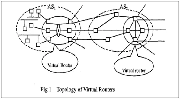
in response to utilization and survivability enhancement in backbone networks. The following
[image:10.612.157.455.236.400.2]figure gives a simple topology of the work done by Qian and Qe[1]:
Figure 1: Topology of virtual routers
In order to perform routing and forwarding functions with the external (physical routers), the
virtual router needs to do the following: first, the virtual router has to obtain routing information
sent by the external routers. Then, this router will execute the flood operation, which means that
this router will send the routing information to all internal nodes. Finally, using external links,
this virtual router will be able to send routing information to exterior routers.
2.1.2 Routing Protocols:
These virtual routers can support interior and exterior routing protocols. For example, OSPF as
well as IS-IS will be run to route traffic within the same AS and BGP with other ASs as a border
router. In contrast, my research is intended to only use interior routing protocols such as RIP,
the network. In addition, cluster-based virtual routers are a solution for ISPs. My experiment will
be of primary use for educational purpose. For instance, a faculty member may use my virtual
routing appliance to help them set up a fully virtualized environment for their research as well as
a demonstration to students on how routing protocols work.
2.1.3 Testing Environment:
Authors of this paper tested the reliability, scalability, and load balancing. They utilized a
simulation tool which is called "Network Simulator-NS Ver.2". The purpose of this application
is to test the ratio of bandwidth of the external link as well as the load.
This paper is different from mine in many ways. The paper done by Qian and Ge is targeting
data centers. They proposed a solution to fulfill the requirement of backbone networks'
survivability and scalability. This issue led them to embed virtual routers between local networks
and the ISP. The reason is to allow these virtual routers to organize and schedule packets in a
particular AS (Autonomous system). The key advantage in my architecture from this paper is
that mine will be completely virtualized while this paper uses virtual routers mainly in the
middle of the network topology.
2.2. Xen Router Virtualization:
Xen is an open source virtualization project hat provides similar virtualization services as
VMware except with a more integrated hypervisor. This can only work under Linux operating
systems [2].
According to [3], the architecture of Xen simulates that there are multiple domains and a Xen
hypervisor in each physical computer. The Xen hypervisor (also known as the Virtual machine
monitor) has the responsibility of managing the access to the physical resources at the computer.
In addition, each domain controlled by the Xen hypervisor represents a single virtual machine.
The authors of this research point out that in case one of those virtual machines needs to utilize
privileged command, a module called hypercall must be used. The function of this module is to
inform the hypervisor that a virtual machine needs to perform a privileged instruction.
The first virtual machine in Xen is named "domain0". This domain is used by system
administrators in order to start a new virtual operating system. Furthermore, when the hypervisor
boots, dom0 automatically boots and controls management of the physical hardware. In addition
to that, all drivers are stored in dom0 (also known as IDD, Isolated Driver Domain), so all
devices kept in dom0 are accessed by all other domains through point-to-point links [3].
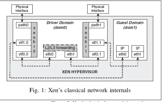
The following figure illustrates the Xen's system architecute. The operation of forwarding
packets in Xen has been divided into three methods. The first one is called bridging [3]. In this
mechanism, in order to permit transparency for applications between the real and the virtual
interface, Xen utilizes bridging along with dom0. The purpose of the following figure is to show
how the packets have been moved from the Driver Domain (dom0) to the guest domain (dom1)
Figure 2: Xen’s classical network internals
The second mechanism is called routing. Unlike the first mechanism, IP addresses are required to
be assigned to interfaces in the guest domains and dom0 to facilitate packet routing. The
following figure shows how this operation is accomplished. In this case, packets are first moved
from the dom0's physical interface (noted as ethY interface) to the proper back-end interface,
vifX.Y. Then, it is the responsibility of the Xen hypervisor to route the packets from both
back-end interfaces reside in dom0 and domU.
[image:13.612.178.436.510.675.2]2.2.2 Routing Protocols:
This paper does not indicate any routing protocols used in the Xen architecture. This is
reasonable because all network traffic occur internally (in the same subnet). This means that
there is no need for routing protocols to be deployed in this scenario.
2.2.3 Testing Environment:
Clark developed an architecture called the Heterogonous Experimental Network (HEN) testbed.
This environment basically consists of many network hosts with different capabilities. Every
node in HEN has multiple interfaces which makes it easy for an experimenter to change the OS
in the node in a timely manner. The testbed consists of three components: traffic generator,
traffic sink, and the system under test. They used Dell servers in order to perform both traffic
generator and traffic sink and a Sun Fire X4100 with one 2.2 GHz AMD for the system under
test.
Even though this paper seems to have some points in common with my research such as using
hypervisors to manage all guest domains, it is slightly different from the solution I propose. In
my case, I will be using open source tools in order to perform routing functionality to transfer
packets between the virtual routing appliance and hosts.
Some attempts have been made towards virtualization using network programmability.
Programmable networking aims to simplify the use of network services. As a result, the network
will be able to provide the process of service creation and deployment [4]. The next paper
examines the use of programmable virtual routers in virtual personal overlay networks.
2.3.1 Virtualization mechanism:
Louati and Zeghlache suggested a new method of facilitating communication between Virtual
Private networks. A virtual router model must be utilized in both providers' edge (PE) networks
in order to simplify the dynamic deployment and management of Virtual Personal Overlay
Networks (VPONs). A VPON is defined as a number of network tunnels that specify a virtual
overlay of individual clusters on top of the actual network communication topology [5].
Moreover, a new terminology has been introduced in their research which is Personal networks
(PNs). A personal network is a set of clusters that involves wireless nodes around the user that is
called the Private Personal Area Network (P-PAN) [5].
Louati and Zeghlache outline in their paper two different types of VPON: user-managed VPON
and provider-provisioned VPON. The difference between these two categories is that the first
one has the VPON application deployed and maintained by the user. However, the second
category relies on the service provider for managing and deploying the VPON service [5]. Thus,
in order to make this happen, programmable virtual routers are needed to run on both edge
nodes. As a consequence, these two virtual routers will provide flexibility and will support
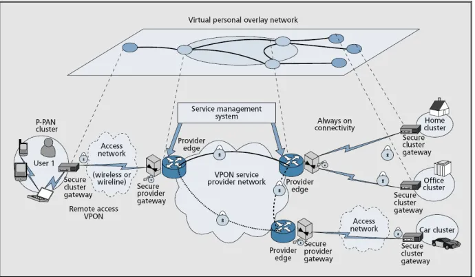
The following figure depicts the provider provisioned network-based VPON remote access
VPON approach. In this example, the VPON involves both secure cluster gateways and secure
provider edge. As we can notice from the figure, any wireless nodes in the P-PAN cluster needs
to establish a connection with the secure cluster gateway. This will ensure a connection in a
secure manner. As a result, all nodes in the network can communicate with each other using the
VPON. The provider edge (PE) routers are required to be flexible, adaptive, and self-organized
in order to support the dynamic aspect. As a result, programmable virtual router instances need
[image:16.612.135.480.292.493.2]to set within PEs [5].
Figure 4: virtual personal overlay network
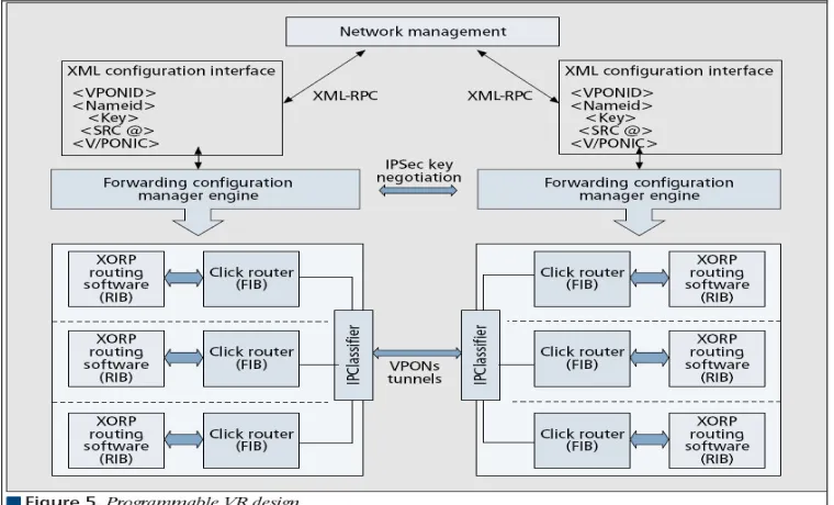
In order to provide the routing decision between different programmable virtual router instances,
a Click router in being used. The Click router is a software architecture and is used to facilitate
the design of the router forwarding mechanism [5]. The following figure demonstrates the design
of a virtual router. An IP classifier is responsible for isolating the incoming traffic coming and
going from all virtual router instances. In addition, each one of those intake has its own logical
VPON-ID. Louati and Zeghlache stated that "The VR instance and IP classifier parameters are
[image:17.612.117.497.127.357.2]added at runtime when a new VPON-ID is provisioned by the management plane into the PE ".
Figure 5: Programmable VR design
2.3.2 Routing Protocols:
Even though this paper does not mention what routing protocols they used for the experiment, it
seems that a combination of interior and exterior routing protocols is deployed. We can clearly
see from figure 4 that three gateways have been used to perform the routing decision. Some of
those protocols that I would imagine may include OSPF, IS-IS, and RIP.
2.3.3 Testing Environment:
In this research, the authors implemented their virtualized environment using Click Router. It is
innovative application architecture for creating configurable routers. Elements are packet
processing modules that are the input in order to assemble a Click Router. According to Morris,
Kolher, Jannotti, and Kaashoek, Individual elements implement simple router functions like
This research is different from mine because it is intended for ISPs. It helps edge providers and
maintains a network infrastructure to connect their users including wireless hosts with each
other. In terms of programming, as was observed in the above figure, the authors employ XML
(Extended Markup Language) in order to forward network traffic. On the other hand, the virtual
routing appliance will be quite simple in terms of implementation. It will only provide access to
wired users that will be administrated within the same AS. Additionally, if needed, the interfaces
attached to the virtual routing appliance will be programmed using Perl or Shell programming
languages.
2.4. IP Infusion Virtual Routing for Provider Edge Application:
The idea of using virtual routing has been introduced and published by ISPs and other firms that
are interested in this topic. According to [7], the authors of the article suggest that Internet
Service providers may need to use Virtual Private Network (VPN) to solve the issue of
scalability. Deploying VPN services instead of utilizing real network hardware will help
companies to decrease the cost to the end user. They define "Virtual routing" as a router which
can be configured to act as multiple routers in the same time [7].
2.4.1 Virtualization mechanism:
Then, the authors demonstrated some general requirements that must be taken care of before
deploying virtual routers. First, each virtual router needs to be completely separated from other
router and must have its own information about the routing decisions and protocol. Also, in
that specific virtual router, and these administrators are required to apply standard management
protocol and services [7].
There are also some VPN specific virtual router requirements associated in this technology. They
stated that all routers should share the same VPN id if they are members in that specific VPN
domain. Additionally, they said that any routing protocols can be used in the backbone network
as long as they do not affect the traffic flow of the VPN services. From security point of view, it
is recommended that designers need to provide some level of security such as authentication and
encryption in the network where needed.
In this solution, the authors point out that all virtual routing occur in the software layer. This
layer is basically an emulation of the physical router in the application layer. The virtual router
consists of all components that might be expected on a physical router. Furthermore, there is a
new component that is called "VR Management Authority". This element is responsible for
maintaining the router configuration and managing the configuration of the router.
2.4.2 Routing Protocols:
The virtual router has a set of routing protocols for performing routing decision. This may
include learning the routes about other networks, building relationship with neighbor routers, and
discovering neighbors. There is also a component called "Forwarding Plane Base". This is used
by the TCP/IP stack to send packets to a particular virtual interface, and when we want to
forward packets, it is the role of the TCP/IP stack to decide the appropriate FIB to use based on
the received interface. IP Infusion virtualized environment initially focuses on BGP, static
2.4.3 Testing Environment:
Throughout the IP Infusion's discussion, the authors focus mostly on the concept of virtual
routing. They do not explain which testing applications they use to test their experiment.
However, this is going to be different from my research. One of the tasks that will be included in
my research is to implement a testing environment in order to measure the quality of the routing
decision.
In general, this solution is good for Internet service providers to deliverer packets from one
machine to another over the Internet/Intranet. IP Infusion suggests using virtual routing along
with VPN to reduce the cost of using many network resources and make it easy for network
designers to scale their networks based on this technology. Unlike this research however, the
virtual routing appliance that I propose will be focusing not only on the routing protocols, but it
will provide a testing environment for the topology that will be created. Furthermore, this
research is intended to be a solution for ISPs and mine will be used towards educational
environment.
2.5 VROOM: Virtual Routers On the Move:
Network management is not new in the area of networking. Much research has been published
looking as ways to address issues such as scalability, availability, or redundancy. Other
researches have dealt with problems allowing virtual routers to move from one physical router to
another without the need to change the IP address. The next paper with discuss this technology in
2.5.1 Virtualization mechanism:
Wang, Merwe, and Rexford propose a new solution for allowing a virtual router to easily move
from one physical router to another. They came up with a new technology which is called
VROOM (Virtual ROuter On the Move).The authors argued that in order in reduce the
complexity of network management, there is a need to split the physical and the logical
configuration of a network. As was discussed in their research, VROOM is a new architecture
that has the ability to give the virtual routers the absolute freedom to move from one physical
node to another.
Furthermore, VROOM does not disrupt the flow of traffic or modify the logical topology when
VROOM migrates with a virtual router to a different physical router. This sometimes occurs
when a physical router must go for planned maintenance. The virtual router can move to another
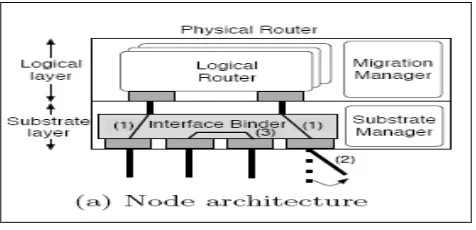
physical router in the same Point-of-Presence (POP). The following figure depicts a router in the
VROOM architecture. The figure yields that there are two layers, a substrate layer and a logical
layer. According to [8], "The primary purpose of the substrate layer is to provide a dynamic
binding between the interfaces of the logical routers and interfaces and links in the substrate
level". On the other hand, the logical layer includes virtual router and is the same as the today's
Figure 6: VROOM node architecture
In the next figure, Router A is re-binding from router B to router C using the programmable
transport. The research that is done in this paper suggested that in order to make this happen, two
extensions need to be made. The first extension is to dynamically adjust the binding between the
physical host and its logical router. Secondly, the virtual router needs to migrate from one
physical router to another.
Figure 7: Programmable transport re-homing with interface re-binding
2.5.2 Routing Protocols:
The authors of this research deploy the Border Gateway Protocol (BGP) which is the core
routing protocol of the Internet. BGP does not utilize traditional interior gateway protocols
[image:22.612.98.515.356.521.2]2.5.3 Testing Environment:
The network topology consists of two subnets. Each subnet has four physical servers. The goal
of this topology is to study the round-trip delay time for the migration. The authors did not spend
much time testing and verifying the technologies they discussed in their research.
In conclusion, this research is different from mine in many ways. First of all, the authors run
their virtualized experiment under Linux OS using Xen virtual machines. In my experiment, I
will intend to use VMWare in order to create a virtual environment. Also, this research was a
primary target at ISP network so it will facilitate traffic moving among backbone routers. On the
other hand, my paper will aim to be used in education. Lastly, it is clearly seen that VROOM
research lacks a clear testing methodology and uses powerful testing tools in order to accurately
measure different aspects of monitoring their testing environment. However, in my experiment, I
am using tools such as Nagios and I-ITG to generate and test packets coming from virtual
machines.
3. Routing Protocols in a Virtual Environment:
The purpose of routing is to decide where to send network packets intended for addresses that are
located outside the local network. Routers, specifically virtual routers, collect and maintain
Conceptually, there are two basic methods for routing. Routers can utilize planned static routes,
or they can dynamically compute routes using any routing protocols, such as RIP, or OSPF. The
second type of routing has the ability to discover routes when those routers broadcast their
routing tables through Ethernet or serial interfaces.
For the purpose of my thesis, no static routes are used within the virtual routing appliance.
Instead, the above dynamic routing protocols are the core protocols that are used for the scenario.
The next few paragraphs discuss these routing protocols in detail for better understanding of how
they are actually designed and how they work.
Routing Information Protocol (RIP):
RIP is considered to be one of the oldest routing protocols. This protocol calculates routes by
using distance-vector algorithms. RIP is most functional as an interior gateway protocol [9].
Thus, it is not common that to see this protocol used in Internet. Routing protocols that are
controlled and administrated within the same autonomous systems are referred to as an interior
gateway protocol. Some of capabilities and features that RIP supports will be discussed next.
This includes routing timers, routing update process, routing stability, and RIP routing metrics.
RIP broadcasts its routing information at regular basis and when the network topology alters. In
case any changes occur in the topology, the virtual router updates its routing table to adopt the
new route. When the virtual router uses RIP, it only maintains the best route to a destination
routing table. In terms of routing metrics, RIP only uses one metric, which is the hop count, for
routing calculation between a source and destination network. Each path from the source to the
destination is given a value. Therefore, when a packet leaves the source machine and reaches the
first virtual routing appliance, the hop count is incremented by 1 and that is added to the metric
value.
RIP maintains routing stability by avoiding routing loops from occur. It limits the number of the
hop count that is allowed in a path between the source and the destination. The virtual routing
appliance will drop packets that have hop counts exceeding 15 and the network destination is
considered unreachable [10]. RIP route timers are used to maintain the validity of each route that
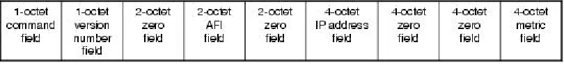
[image:25.612.104.509.403.450.2]is saved in the routing table. Figure 1 depicts the RIP packet format that consists of nine fields.
Figure 8: RIP packet format
As we saw in the previous figure, a RIP packet format consists of nine fields. This paragraph will
expand each component listed in the format. The command field which requires one octet shows
whether the packet is generated as a request or as a response to a request. In the first case, the
request asks the virtual router to send all or part of its routing table. A response packet can be
generated in either response to a request or as an unsolicited update [10]. The version number
field is used to determine a RIP version that was used to generate the RIP packet. Yet, only two
features that RIP 2 provides but not RIP1 are authentication and subnet masking. RIP 2 has the
ability to use a simple authentication mechanism to secure table updates. More importantly, RIP
2 supports subnet masks. If the network address does not have a subnet mask, this field is set to
zero.
The Address-Family Identifier (AFI) indicates the address family used. RIP is implemented to
provide routing information for different protocols. Consequently, the open standard RIP needed
a mechanism for determining which type of address is being carried in its packets. The AFI for
IP is 2. The address field contains an internetwork address. This can be a gateway, a network or
even a host. Finally, the metric field specifies the number of virtual routers have been traversed
to the destination. This value is incremented as it passes through a virtual router. The following
paragraph explains the commands that are used in my experiments for RIP.
Traditional routing applications present all of the routing protocol functionalities as one process
software. However, Quagga approaches this differently. Quagga is implemented from a number
of many daemons that work collectively in order to construct the routing table. In Unix and other
multitasking operating systems, a daemon is a computer program that runs in the background,
rather than under the direct control of a user [11]. For example, the Ripd daemon deals with the
RIP protocol; the last letter “d” represents the term “daemon”. In addition, there is a kernel
routing table manager zebra daemon which is running under the virtual routing appliance
machine. This is used to update the kernel routing table and for redistribution of routes between
routing system, this can be accomplished by running only the protocol daemon associated with
routing protocol in use.
The first command that needs to be issued is router rip. This command is necessary in order to
enable RIP protocol. This command must be entered before issuing any other RIP command.
Then, RIP protocol needs to be set by a network. The command for this is network a.b.c.d. For
example, if network 10.0.0.0/24 was RIP enabled, this would result in all pool addresses from
10.0.0.0 to 10.0.0.255 being enabled for RIP protocol. Another command that can be optionally
used is neighbor a.b.c.d. It is to establish a direct link between virtual routers when a neighbor
does not understand multicast.
Although RIP protocol has been marvelously suited during the early days of networking,
technology has radically adjusted the way internetworking used and built. Some of the greatest
limitations of RIP protocols are failure to support paths longer than 15 hops, relatively slow
convergence, reliance on fixed metrics to calculate routes, and inability to provide dynamic load
balancing.
Open Shortest Path First (OSPF):
OSPF is the second virtual routing protocol that is supported in my experiment. This paragraph
sheds some light on this protocol. One endeavor to enhance the scalability of networks was to
base routing decisions on link states rather than hop counts or other distance vectors. OSPF has
two major features. The first characteristic is that the protocol is open, which indicates that its
Shortest Path First (SPF) algorithm, which is also referred to Dijkstra’s algorithm [12]. This
algorithm permits the selection of routes based on link states, as opposed to only distance
vectors. This protocol was originally implemented as an IP routing protocol for exercise within
autonomous systems. Therefore, OSPF is not capable of carrying out datagrams of other routable
networks such as Apple-Talk or even IPX.
One of the key advantages that an OSPF supports is the ability to rapidly detect topological
changes in the autonomous system. Other advantages include calculating a separate set of routes
for each IP type of service, utilizing multicasting to minimize the load on systems not
participating OSPF and carrying out data equally between equal-cost routes [13]. Unlike RIP
protocol, the core concept of OSPF routing protocol is that it works within a hierarchy. The
biggest part of the hierarchy is the autonomous system. Each AS can be divided into several
areas which can possibly contain a group of contiguous networks as well as hosts. Virtual routing
appliance can be assigned to different areas based on interfaces that re associated with a network.
Figure 9: OSPF in a virtual environment
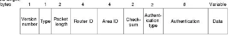
This paragraph discusses an OSPF packet format. OSPF is considered to be a fairly complex
routing protocol. Thus, it utilizes an extensive amount of data structure and each structure
executes a particular task. This is identified as the OSPF header. The following figure shows the
Figure 10: OSPF packet format
• Version Number: The first field seen in an OSPF header is intended to identify the
version number. The current virtual routing appliance that I am proposing supports OSPF
version 2 and version 3.
• Type: This field explains which of the five different OSPF packet types is associated to
this specific header. The header type can be one of the following:
o Hello packets (type 1): Is utilized to initiate and maintain relationships among
neighboring virtual routing appliance.
o Database description packets (type 2): This packet is used between two OSPF
virtual routing appliances in order to build an adjacency.
o Link-state request packets (type 3): This packet describes a virtual routing
appliance requests particular piece from a neighboring virtual routing appliance.
This happens when the neighboring virtual routing appliance has more current
information.
o Link-state update packets (type4): This packet is response to link-state request
packets and is responsible to carry out Link-state Advertisements (LSAs) to
neighboring virtual routing appliances.
o Link-state acknowledgment packets (type 5): This packet ensured reliability of
LSA packets distribution. Therefore, the receiver virtual routing appliance must
• Packet length: This packet is used to notify the receiver the total length of both the
payload and the OSPF header.
• Router ID: Each virtual routing appliance is given a unique ID number. It is populated
by the OSPF protocol before sending any other information to other virtual routing
appliances.
• Area ID: As discussed in figure 3, this field is responsible to specify the area ID number.
• Checksum: This field stores a result of a mathematic algorithm calculation to make sure
that a packet received is identically the same as the on sent.
• Authentication type: Involves the authentication type. Each virtual routing appliance
must be authenticated during OSPF protocol exchanging.
• Authentication: This filed is used for actual carrying of authentication information.
• Data: Contains encapsulated upper-layer information.
In order to start the OSPF configuration process in Quagga, it is necessary to first identify the
OSPF virtual routing appliance. The command router ospf enables the OSPF process. The
second step is to set up the virtual routing appliance ID of the OSPF process. This can be
accomplished by issued ospf router-id a.b.c.d command. The ID number can be either an IP
address of the virtual routing appliance or any arbitrary 32 bit number and must be unique. The
next step is to associate a network as well as an area to a specific interface by typing network
OSPF is considered to be one of the most great and provides several features in terms of open
source routing protocols. Its complexity is probably the biggest limitation because building,
maintaining, and designing OSPF networks require a degree of expertise. One way to decrease
this complexity to use the default setting which greatly helps to simplify the design of this kind
of networks. When setting properly, users will notice quick convergence and solid performance.
4. Creation of Virtual Networks:
Three virtual routing appliances are utilized in this research in order to test the traffic behavior.
Those virtual routers are the core aspects and act as packet forwarders between heterogeneous
LANs. Routing decision is made based on the routing table resides in each configuration of the
virtual routing appliances. Additionally, six VLANs are created using VMware features in order
to ensure that all VLANs are isolated from each other and there is no way for packets to be
forwarded among VLANS unless there is a layer three device. The network topology shown
below is used to perform two different experiments. Each one of those experiment employs
specific dynamic routing protocol, RIP and OSPF respectively. I am using 192.168.X.X IP
Figure 11: General VRA topology
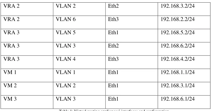
The above figure shows that some nodes have three interfaces. This can be possibly added
using the VMware feature called “Add Adaptor”. It is important to know which interface
corresponds to which IP address. The following table illustrates all interfaces in the previous
network topology and the IP address associated with each adaptor.
Device Name VLAN Name Interface/Adaptor IP Address
VRA 1 VLAN 6 Eth1 192.168.2.1/24
VRA 1 VLAN 1 Eth2 192.168.1.2/24
VRA 1 VLAN 4 Eth3 192.168.4.1/24
VRA 2 VLAN 2 Eth2 192.168.3.2/24
VRA 2 VLAN 6 Eth3 192.168.2.2/24
VRA 3 VLAN 5 Eth1 192.168.5.2/24
VRA 3 VLAN 3 Eth2 192.168.6.2/24
VRA 3 VLAN 4 Eth3 192.168.4.2/24
VM 1 VLAN 1 Eth1 192.168.1.1/24
VM 2 VLAN 2 Eth1 192.168.3.1/24
[image:34.612.65.511.67.302.2]VM 3 VLAN 3 Eth1 192.168.6.1/24
Table 1: Virtual routing appliances’ interfaces and configuration
The previous table shows that all virtual routing appliances have three interfaces. Each interface
is assigned into different VLAN. As a result, for example, if VM1 needs to send packets to
virtual routing appliance 1, packets should be forwarded to Eth2 in the virtual router. This
ensures that all VLAN are totally isolated from each other. The following screenshot is taken
5. Installations and Configurations:
Three major applications are needed to be set up and configured in order to establish the test
environment for my experimental research. One physical machine is used to emulate this testing
environment. Quagga, which is a newer version of GNU Zebra project, is installed in two virtual
routing appliances that are running under Linux Ubuntu OS. These virtual routing appliances
represent the core function for routing between virtual hosts that are running under Windows XP
SP2. In this sense, most of the configuration and tuning are applied to the virtual routing
appliances. This component utilizes the same Cisco ISO commands for routing. Although
Quagga is intended to work under a physical machine, it can be tuned to work in a virtual
environment. In addition, Nagios, which is a tool that performs monitoring tasks, is installed in
both virtual routing appliances. Even though all these nodes are residing in the same physical
machine, they are totally isolated into three subnets. This involves virtual Network Interface
Cards (NICs) on both virtual hosts and virtual routing appliances.
Hardware and Software Specifications:
1. Laptop
• Processor: Intel Pentium® M 2.00 GHZ
• RAM: 1 GB
• Hard Disk: 80 GBs.
Step 1: Installation and Configuration of Quagga:
Ubuntu 7.10 the Gutsy Gibbon release, which is a Linux based OS, has been selected as the
foundation for Quagga. The only prerequisite to get Quagga to work is to update all packages
from Synaptic Package Manger and choose to install Quagga. This experiment uses Quagga
0.99.9 release which supports BGP4, BGP4+, OSPFv3, IS-IS, RIPv1 as well as RIPv2. An
operating system with Quagga installed operates as a dedicated router. Using Quagga, a virtual
machine can exchange routing information with other virtual routers utilizing routing protocols.
Quagga takes advantage of this information to update the kernel routing table so that the right
packet is forwarded to the right destination. The latest version of GNU Quagga can be
downloaded from http://www.quagga.net. The simplest way to install this package after
downloading is to type the three following commands:
% configure
% make
% make install
The next step is to configure and make some adjustments to this utility. It is necessary to specify
what routing protocols Quagga is going to support. By default, the only routing protocol that
Quagga supports is RIP. In order to change the default configuration, a user needs to activate the
Quagga daemons matching the routing protocols that are required on a virtual routing appliance.
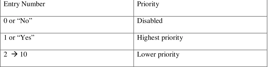
The following command allows the user to choose the proper routing protocol:
#vim /etc/quagga/daemons
Entry Number Priority
0 or “No” Disabled
1 or “Yes” Highest priority
[image:37.612.66.511.73.185.2]2 10 Lower priority
Table 2: Quagga configuration’s options
The “daemons:” configuration file looks like the following:
Notice that in the following example zebra, ospf and rip routing protocols are included and the
OSPF has a higher priority when routing information than rip.
zebra=yes
bgpd=no
ospfd=yes
ospf6d=no
ripd=2
ripngd=no
isisd=no
After successfully choosing the routing protocols for your needs, it is required to create a
configuration file every time a Quagga daemon is activated. There can be six configuration files
based on the implementation of a virtual network. For instance, files such as bgpd.conf and
ripd.conf are used in order to store configuration commands within these two specific files. Upon
starting Quagga, these files are loaded into the running configuration in the virtual appliances’
memory. This will facilitate a user ability to enter a set of commands in the Quagga command
!
! Zebra Configuration Saved from vty ! 2008/06/11 04:11:31
!
hostname Router
enable password zebra !
interface eth0
ipv6 nd suppress-ra !
interface lo !
linevty
Sample of Zebra config file
!
! Zebra Configuration Saved from vty ! 2008/06/11 04:11:31
! hostname ripd password zebra log stdout ! Router rip ! line vty !
Sample of ripd config file
The first config file basically assigns a hostname to the virtual router as well as the password. It
also states that these commands have been entered via a local administrator. The other config file
has almost the same characteristics except that the virtual router utilizes rip as a routing protocol.
Finally, it is necessary to provide a user or group ownership to Quagga and Quaggavty
respectively to the files inside the /etc/quagga directory:
#chown quagga.quaggavty/etc/quagga/*.conf
#chmod 640 /etc/quagga/*.conf
Step 2: Installation and configuration of Nagios:
Nagios is installed on the target virtual routing appliances. For monitoring purposes, it is
important to install and configure this software in order to study the results. Before installing
Nagios, a user must install the following packages:
• Apache2: Apache provides several features, many implemented as complied modules
that expand the major functionality. These range from a server-side programming
language scheme to authentication support. Apache is essentially utilized to support both
static content such as text and pictures and dynamic Web pages such as Flash
technologies. The combination between Nagios and Apache enables me to use the web
interface to poll the status of different hosts that are assigned in the configuration file for
Nagios. The following snapshot explains the different services that monitor the localhost
[image:39.612.101.534.428.673.2]that resides in the virtual routing appliances.
• GCC compiler and development libraries: GNU Compiler Collection contains a number
of compliers implemented for various programming languages by the GNU Project. The
GNU compiler was originally produced to only handle C programming language. By the
time, this project was extended to compile Java, C++, Pascal, and FORTRAN. This
package is mandatory in order to compile the Nagios that is written in C.
• GD development libraries: GD library stands for Gif Draw and is used to manipulate
images. Additionally, it can create other image formats such as PNG, JPEG and WBMP
images. This package is required in Nagios since there is an option to visualize the host
machines from the web interface.
The configuration of Nagios begins by creating a new Nagios user account and giving it a
password. This step is important for authentication purposes when a user needs to connect to the
web interface. The following sets of commands should be utilized to create a new user:
#/usr/bin/useradd nagios
#passwd nagios
Step 3: Installation and configuration of Distributed Internet Traffic Generator
D-ITG Configuration:
D-ITG offers two options for packet delivery. The first one, which works under Windows OS,
and requires a user to type commands manually. Several parameters cab be assigned in a D-ITG
command such as delay meter, protocol, source and destination ports, traffic speed and volume.
Snapshot Sample of D-ITG GUI Interface
Component of D-ITG:
ITGSend: this is the sender component of the D-ITG component. ITGSend creates several
simultaneous flows of protocol traffic. It is a multithreaded platform accountable for producing
and sending network packets according to particular input parameters [14]. This component
exists on the sender virtual host and has the capability of generating a number of several flows
concurrently. Each flow is managed by a single thread. The traffic flow behavior can be
controlled by various command line options. As listed above, those options may include but are
not limited to meter (one way delay or round trip delay), source and destination ports, packet
ITGRecv: This component has the role of receiving traffic sent by ITGSend. It should apparently
run on the receiver virtual host to achieve a connection [14]. It is mandatory to synchronize the
clocks in the sender and the receiver virtual hosts for accurate results when calculating one way
delay. Clocks can be not synchronized if a round trip delay is utilized for measurement of the
delay. The logs may be sent to a third virtual host but I chose to capture it locally on the
receiving virtual host for the purpose of this testing.
ITGDec: This is the decoder component and is responsible for analyzing the results of the testing
generated by utilizing the D-ITG platform. It parses the log files generated by ITGSend and
ITGRecv components and computes jitter, delay, and bit rate at specific intervals on the test as a
whole. Delay is the time variation between sending and receiving packets. On the other hand, the
testing time is between the reception of the first and last packet received by the ITGRecv
component.
[image:42.612.89.524.458.652.2]
6. Observations and Findings:
RIP Scenario:
The first routing protocol installation in my proposed virtual environment is RIP. As discussed
earlier in this report, RIP relies only on hop count to measure a cost to a given route. It is
important to notice that all links in this topology have the same link speed although it is not
affecting the routing decision for any of the virtual routing appliances. The following drawing
gives a better understanding of the whole environment including the three virtual routing
appliances as well as the virtual machines.
RIP
RIP
R IP
R IP
[image:43.612.90.522.336.605.2]Figure 14: RIP topology
After configuring those virtual routing appliances to be RIP capable, all router are staring to
learn new networks. Upon configuring RIP protocol in the virtual routing appliances, each
observation is that all virtual routers are successfully able to learn all routes in my topology and
hence can ping any virtual appliance/machine. The following is a screenshot taken from the first
virtual appliance when typing show ip route.
The above screenshot shows many routes that need to be explained in this paragraph. First, the
“C” sign indicates that loopback address for that specific machine. This is generally used for
testing purpose to ensure that that machine can ping itself. The “K” sign is only found if one
used GNU Zebra which refers to a kernel route. The idea behind it is that Gnu Zebra supports
multi-thread by combining all routing protocols into single configuration file.
I also found that three routes are directly connected to the first virtual appliance. The reason is
that this virtual machine is assigned with three NIC different interfaces and referred to the
symbol “C” which means that this route is directly connected to the virtual machine. Finally and
most importantly, I observed that three new routes have been learned from neighbors. Going
back to the topology, we can obviously see that 192.168.3.0/24 network has been learned via the
The value of 120 indicates the administrative distance of the information source which is RIP in
this topology and the hop count value in this case is 2 because packets are forwarded through
two virtual routers to reach to that specific network. Eth5 means that RIP has been advertized by
this interface. The last value specifies the last time the route was updated, in hours: minutes:
seconds.
The last observation in this section discussing the path are taking when leaving the first virtual
machine and targeting the second virtual machine. After studying the behavior of RIP protocol
and applying its configuration in my virtual environment, the result was that the sender virtual
machine is taking the shortest path to the destination which goes through VLAN6. The next
drawing clearly demonstrates the behavior of packets sent from the first virtual machine to the
[image:45.612.89.523.429.688.2]The following is a tracert command issued from the first virtual machine and targeting the
second virtual machine. The result is that all packets are traversing from VRA1 to VRA2 which
OSPF Scenario:
The second experiment that is conducted in this research uses an OSPF protocol in all virtual
routing appliances. Unlike the RIP protocol, OSPF depends on different measurements and
criteria when calculating routing paths. As described in RFC, the OSPF protocol employs path
cost at its basic routing metric. In practice, it is known by the link speed (bandwidth) of the
interface addressing the given route. In my virtual network environment, I tend to use mixed
speed that can be set up from the VMware options and from a virtual routing appliance command
line. The following drawing shows all VLANS associated with their link speed. This enables me
to study the behavior of the OSPF protocol.
[image:47.612.90.525.321.582.2]OS PF OS PF O SP F O SP F C o s t= 1 0 Co st= 10 C o s t= 1 0 Co st= 10
The purpose of this experiment is to see what path packets are taking when sending traffic from
the second virtual machine to the second virtual machine. It is important to notice in the above
topology that not all links have the same speed of bandwidth. The screenshot taken from the first
virtual appliances explains the path cost for all three interfaces connected to that virtual node. It
shows that the Ethernet1 and Ethernet3 have the path cost of 10, meaning that their speed links
are 10 Mbps. On the other hand, I tuned the speed link for Ethernet2 to be 56 Kbps using the
bandwidth 56 command. As a result, Ethernet 1 and Ethernet 3 have a total path cost of 10 and Ethernet 2 has a cost of 1786. This means that Eth1 and Eth3 have a higher priority when
sending traffic.
One of the key observation when looking at the routing table of the first and the second virtual
routing appliances is that they have two paths to the same destination in case all their interfaces
have the same link speed. However, the following routing table taken from the first virtual
selects the best route to the destination and stores it in its routing table. Note that the first routing
appliance in this scenario is forwarding packets to 192.168.4.2/24 when the first virtual machine
pings the second virtual machine.
The next screenshot obtained from the first virtual machine shows the complete route from the
first virtual machine to the second virtual machine. It explains an obvious observation that the
Determination of Latency: Part 1: TCP
Delay measurement with RIP protocol
This section presents the commands utilized for measuring latency induced by RIP protocol for
each of the two protocols of TCP and UDP. The precise commands and their output are shown.
The results points out the average delay for each packet. A delay measurement is applied for
both RIP and OSPF scenarios and the results are summarized in the table at the end of this
section. All the following commands are generating from the first virtual machine and targeting
the second virtual machine.
Command: ITGSend.exe –m rttm –a 192.168.3.1 –rp 10001 –T TCP –t 30000 –l send_tcp_rip –C 100000 –c 1000
---
Flow number: 1
From 192.168.1.1:1036
To 192.168.3.1:10001
__________________________________________________________
**************** TOTAL RESULTS ******************
__________________________________________________________
Number of flows = 1
Total time = 29.970407 s
Total packets = 31717
Minimum delay = 0.010905 s
Maximum delay = 0.681792 s
Average delay = 0.131910 s
Delay standard deviation = 0.069519 s
Bytes received = 31717000
Average bitrate = 8466.218026 Kbit/s
Average packet rate = 1058.277253 pkt/s
Packets dropped = 0 (0.00 %)
Delay measurement with OSPF protocol
Command: ITGSend.exe –m rttm –a 192.168.3.1 –rp 10001 –T TCP –t 30000 –l
send_tcp_ospf –C 100000 –c 1000
---
Flow number: 1
From 192.168.1.1:1064
To 192.168.3.1:10001
__________________________________________________________
**************** TOTAL RESULTS ******************
__________________________________________________________
Number of flows = 1
Total time = 29.947127 s
Total packets = 7450
Minimum delay = 0.035168 s
Maximum delay = 1.786886 s
Average delay = 0.401525 s
Average jitter = 0.006812 s
Delay standard deviation = 0.309101 s
Bytes received = 7450000
Average bitrate = 1990.174216 Kbit/s
Packets dropped = 0 (0.00 %)
Part 2: UDP
Delay measurement with RIP protocol
Command: ITGSend.exe –m rttm –a 192.168.3.1 –rp 10002 –T UDP –t 50000 –l send_udp_rip –C 100000 –c 1000
---
Flow number: 1
From 192.168.1.1:1055
To 192.168.1.10:10001
__________________________________________________________
**************** TOTAL RESULTS ******************
__________________________________________________________
Number of flows = 1
Total time = 49.974237 s
Total packets = 33367
Minimum delay = 0.000772 s
Maximum delay = 1.453843 s
Average delay = 0.015954 s
Average jitter = 0.001533 s
Delay standard deviation = 0.055672 s
Bytes received = 33367000
Average bitrate = 5341.4722247 Kbit/s
Average packet rate = 667.684031 pkt/s
Packets dropped = 191773 (85.18 %)
Delay measurement with OSPF protocol
Command: ITGSend.exe –m rttm –a 192.168.3.1 –rp 10002 –T UDP –t 30000 –l
send_udp_ospf –C 100000 –c 1000
---
Flow number: 1
From 192.168.1.1:1070
To 192.168.3.1:10002
__________________________________________________________
**************** TOTAL RESULTS ******************
__________________________________________________________
Number of flows = 1
Total time = 30.004165 s
Total packets = 923
Minimum delay = 0.079857 s
Maximum delay = 7.485252 s
Average delay = 0.777670 s
Average jitter = 0.0383684 s
Delay standard deviation = 0.838684 s
Bytes received = 923000
Average bitrate = 246.099167 Kbit/s
Average packet rate = 30.762396 pkt/s
Final results for latency:
For each of the two protocols of TCP and UDP, the results for delay are summarized in the
following table. The latency induced by RIP protocol is unlike the delay with the OSPF protocol.
Finally, the mathematical mean for all two protocols is calculated to show the average latency
induced by RIP and OSPF routing protocols in a virtual environment.
Sr. No. IP Protocol RIP Protocol
(in milliseconds)
OSPF Protocol
(in milliseconds)
1 TCP 131.910 401.525
2 UDP 15.954 777.670
[image:54.612.65.502.209.356.2]Average Latency 73.932 589.5975
Table 3: Latency results
The average latency of all two protocols at 10 Mbps is 73.932 milliseconds for the RIP scenario
and 589.5975 milliseconds for the OSPF scenario.
Determination of Throughput:
This section targets the performance of the virtual environment, particularly the throughput. The
throughput is always measured as a packet per second. Throughput would be to take two
measurements of the total number of packets that have come in or out of a particular interface
and take the packets at the second time and subtract it from the packets at the first time. This
calculates the number of packets that have gone in and out in that time period. Finally, the time
at point one and the time at point two needs to be collected and then subtract them and perhaps
Scale
onds
onds
inPackets
inPackets
ond
pktsPerSec
*
sec
sec
)
(
1
2
1
2
−
−
=
The idea here is simple. The first virtual routing appliance is responsible to monitor the other two
virtual routing appliances and the virtual router itself. The first appliance generates SNMP
requests throughout the network and list the result in a nicely format in Nagios. The following
[image:55.612.89.525.292.555.2]drawing shows the interfaces that send or receives SNMP requests.
Figure 17: SNMP agents’ distribution
The next step is to create services inside Nagios that will appear on the web-based browser. This
browser shows the result of the services that have been generated for each piece of a virtual
router. The two following files need to be created in order to achieve this task. “localhosts.cfg” is
are defined. It also specifies the service’s name that will appear in Nagios and the command
name. The “commands.cfg “shows the actual SNMP command that is used to send a request to a
specific router’s interface. The appendix section lists all the hosts’ and services’ configurations.
An awk script is also created to calculate the throughput for the three virtual routing appliances.
The script stores the initial reading in a separate file. It then computes the second reading and
subtracts it from the first reading. The result of the calculation is shown in Nagios web-browser.
In this example, the RIP protocol is used to route traffic between the three different subnets.
Since the primary concert is to study the throughput in only the three virtual routing appliances,
the other three virtual machines ate omitted from this scenario. The following screenshot taken
from Nagios shows the statistic polls from the web-browser. It is important to note that there are
two types of services I have created; the average packets sent and the average packets received.
The following screenshot and table show the throughput calculated from the awk script and
Machine Name Mode Throughput Rate
(packets per seconds)
VRA1 Sent 0.39945
Received 0.050395
VRA2 Sent 0.00
Received 0.106732
VRA3 Sent 0.0764897
[image:57.612.66.514.70.296.2]Received 0.0460082
Table 4: Throughput results
The average throughput of all three virtual routing appliances is 0.23796985 packets per second
in the sent mode and 0.06771173 packets per second in the received mode.
7.
Final Results and Conclusion
:The last cumulative findings for the quantitative tests accomplished for the virtual routing
appliances are the average of results for the all scenarios for latency and throughput parameters.
Parameter Average Rate
Latency RIP 73.932 milliseconds
Throughput Sent 0.23796985 packets per milliseconds
[image:58.612.60.511.74.131.2]Throughput Received 0.06771173 packets per milliseconds Table 5: Final results
Details of results for each parameter
• Latency (RIP): the latency observed in the RIP scenario is less than from the one found
in the OSPF scenario. The reason is that traffic traverses through two hop counts
resulting in less network latency although the OSPF build relationship with neighbor
virtual routers faster. The value of 73.932 millisecondscame from both TCP and UDP
packets generated from D-ITG and calculated the average of those IP packets.
• Latency (OSPF): the latency of on the other hand found in the OSPF scenario is
obviously much higher than the one seen in the RIP scenario. I had to tune the first
scenario by adjusting the bandwidth between the first virtual routing appliances and the
second virtual routing appliance to be 56 Kbps. As a result, packets are traversing via the
third virtual routing appliance that causes the latency to be higher. In order to get a better
performance, the bandwidth between the three virtual routers should return to their
previous status which is 10 Mbps.
• Throughput (Sent/Received): The throughput values in the above table indicate that the
three virtual routing appliances send and receive traffic at low rates. The reason behind it
is that I intended to isolate my virtual environment from the Internet. However, in order
associate them with each virtual routing appliance. Downloading and uploading files
from the Internet would help enhance the throughput rate for all virtual machines.
The virtual routing appliance lessons the degree of building a virtual environment. It can be
deployed as a virtual router with the assurance of forwarding packets to the right destination.
According to the findings and observations of the tests conducted for this evaluation, a virtual
routing appliance is best suited for educational and experimental purposes. It could usually be
deployed to route traffic between subnets without the need to add physical resources.
8. Future Work:
The evaluation of the virtual routing appliance was conducted with limited routing protocols and
was not using advanced features. The scale of this evaluation can be enlarged by testing the
proposed virtual routing appliance with more routing protocols’ configurations and conditions.
These may include deploying other routing protocols such as EIGRP, BGP, and ISIS. The
research can be also expanded by generating traffic for additional protocols, utilizing multiple
routing protocols in a single scenario. Future research can also involve using Nagios to calculate
9. Bibliography
:
[1] Ge, J., & Qian, H. (2001). Cluster-based virtual router. Retrieved February 23,
2008, from http://www.ieeexplore.ieee.org/Xplore/login.jsp?url=/iel5/7719/
21186/00983561.pdf?tp=&arnumber=983561&isnumber=21186
[2] Clark, C. (2006, September 29). Xen User's Menual. Retrieved April 24, 2008,
from http://www.cl.cam.ac.uk/research/srg/netos/xen/readmes/user/user.html
[3] Egi, N., Greenhalgh, A., Handley, M., Hoerdt, M., Mathy, L., & Schooley, T.
(2007, August 13). Evaluating Xen for Router Virtualization. Retrieved
February 23, 2008, from http://www.ieeexplore.ieee.org/Xplore/
login.jsp?url=/iel5/4317769/4317770/
04317993.pdf?tp=&arnumber=4317993&isnumber=4317770
[4] Campbell, A., Kounavis, M., & Vicente, J. (n.d.). Programmable Networks.
Retrieved Ap