DEVELOPMENTS IN PLANE AND CONCAVE GRATINGS:
THEORY AND EXPERIMENT
by
B.J.Brown, B.Sc.(Hons.), University of Tasmania
A thesis submitted in fulfilment of the requirements
for the degree of
Doctor of Philosophy
in the
UNIVERSITY OF TASMANIA
HOBART
Except as stated herein, this thesis contains no
material which has been accepted for the award of any other
degree or diploma in any university. To the best of my
knowledge and belief, this thesis contains no copy or
paraphrase of material previously published or written by
another person, except where due reference is made in the
text of the thesis.
Barbara J. Brown.
iq fa.' lei
CONTENTS
Page ABSTRACT
ACKNOWLEDGEMENTS
CHAPTER 1 INTRODUCTION AND BASIC THEORIES
1.1 Historical Survey 2
1.2 Comparison of the Properties of
Holographic and Classical Gratings 4
1.3 Diffraction Grating Efficiency 6
1.4 Theories of Diffraction Gratings 9 1.5 Geometric Theory of the Concave Grating 11
1.6 Introduction to Thesis 31
CHAPTER 2 PLANE HOLOGRAPHIC DIFFRACTION GRATING GROOVE PROFILES
2.1 Preliminary Comments 36
2.2 Sinusoidal Groove Profile Gratings 37 2.3 Blazed Holographic Gratings 58 2.4 Fourier Synthesis of Groove Profiles 67
CHAPTER 3 INFLUENCE OF SURFACE COATINGS ON GRATING RESONANCE ANOMALIES
3.1 Preliminary Comments 82
3.2 Bi-metallic Gratings 84
3.3 Conformally Coated Gratings 95
3.4 Concluding Remarks 108
CHAPTER 4 TUNING DYE LASERS AT GRAZING INCIDENCE
4.1 Preliminary Comments 110
4.2 Dye Lasers 110
4.3 Grazing Incidence Grating Efficiencies 111
4.4 Concluding Remarks 115
CHAPTER 5 ROWLAND CIRCLE MOUNT ABERRATION CORRECTION
5.1 Preliminary Comments 117
5.2 Rowland Circle Mount 117
5.3 Aberration Correction Properties of the
Rowland Circle 120
5.4 Image Height and Residual Second
Order Astigmatism 124
5.5 Single Wavelength Correction of Second
Order Astigmatism 125
5.6 Double Wavelength Correction of Second
Order Astigmatism 128
5.7 Double Wavelength Correction of Third
Order Coma 137
5.8 Correction of Astigmatism or Coma in
Two Orders at Two Wavelengths 143 5.9 Simultaneous Correction of Astigmatism
and Coma 150
CHAPTER 6
IMAGE HEIGHT WITH RELATIVE APERTURE
FOR THE ROWLAND CIRCLE MOUNT
6.1
Preliminary Comments
161
6.2
Variation of Image Height with
Relative Aperture
161
6.3
Variation in Numerical Size of the
Aberration Terms of the Light Path
Function
176
CHAPTER 7
DEVELOPMENT OF A UNI-AXIAL DOUBLE
CONCAVE GRATING MONOCHROMATOR
7.1
Preliminary Comments
189
7.2
Minimization Techniques
190
7.3
Concave Grating in an Auto-Collimation
Configuration
195
7.4
Mirror and Concave Grating Mounted
Uni-Axially
209
7.5
Uni-Axial Double Concave Grating
ABSTRACT
The developments in grating performance described in this
thesis fall naturally into two parts according to whether the
grating blank is plane or concave. For plane diffraction gratings,
this study utilizes both experimental work and rigorous electromagnetic
theories to achieve improved grating and instrument performance.
The section concerned with concave gratings is entirely theoretical,
drawing on the manipulation of geometric theories to design high
quality gratings.
Three types of plane diffraction grating grooves currently
generated by holographic techniques are investigated. A discussion
of methods for accurately measuring the groove profile is presented
with particular reference to quasi-sinusoidal groove profiles.
The spectral performance of blazed holographic gratings is shown
numerically to be comparable to that of triangular groove gratings.
Consideration is then given to simple optical arrangements which
permit Fourier synthesis of complex distributions and groove
profiles.
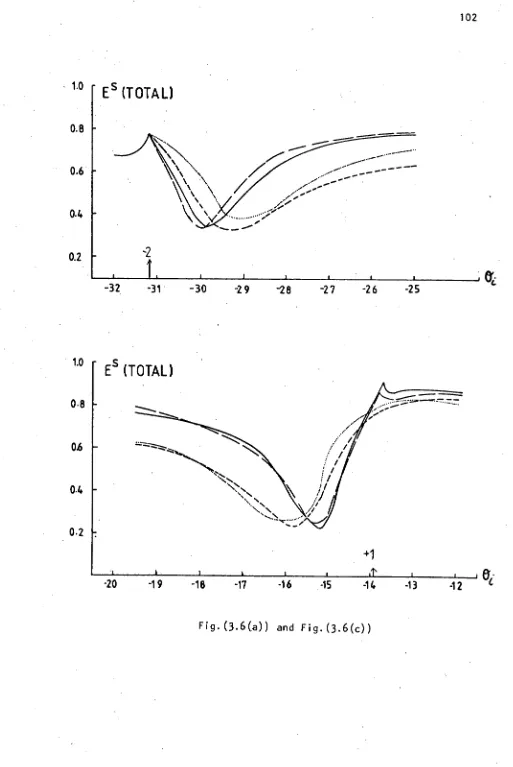
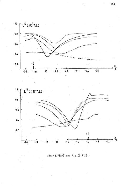
Experimental investigations of the behaviour of resonance
anomalies exhibited by gratings having surface layers of discontinuous
conductivity are presented. It is demonstrated that a coating
consisting of a dielectric overlaid with a metal of high conductivity
drastically reduces energy absorption.
A theoretical search to determine the optimum groove modulation
of both blazed and sinusoidal plane reflection gratings is presented.
This will assist with the development of high-gain dye lasers
Aberration coefficients derived using Fermat's principle
are used for an examination of aberration-correction for Rowland
circle spectrographs. Attention is focussed on the case where
the mounting and recording points lie on the Rowland circle.
Correction at two wavelengths of primary astigmatism or primary
coma under this constraint is demonstrated. Alternatively,
primary astigmatism and primary coma can be simultaneously corrected
over a restricted wavelength range. Some practical implications
are discussed.
The geometric theory of concave gratings is extended to
accommodate higher order aberration terms. The magnitude of the
individual terms of the light path function, which describes image
formation by an aberration-corrected grating, is investigated.
Similarly, the behaviour of the image height under these restraints
is studied for various values of the relative aperture.
Finally, aberration minimization techniques are employed
in the design of a uni-axial, double concave grating monochromator.
The performance of this instrument is evaluated for ruled and
ACKNOWLEDGEMENTS
I sincerely thank everyone who assisted in the formulation
of this thesis, whether their contributions were of a practical
nature or by way of encouragement. Special thanks are due to the
following:
My supervisor, Dr. M.D. Waterworth, whose discussions
throughout the years of investigation spanned by this thesis were
most appreciated. Dr. I.J. Wilson, CSIRO, who as my collaborator
on many of the reported developments aided my insight into the
beauty of the world of the diffraction grating. Dr. E.G.Loewen,
Bausch and Lamb Inc., for his helpful suggestions.
The companionship and continuing interest of my family and
fellow Ph.D. students played a significant role in the completion
of this thesis.
Several members of the University staff deserve mention.
The staff of the University Computing Centre for the generous
provision of computing resources. Barry Wilson and the technical
staff, Department of Physics, have assisted in the construction and
development of equipment. During the early months of my Ph.D.
candidature, experimental work was conducted within the Central
Science Laboratory. I thank the staff for making the facilities
available. In particular, I am grateful to Dr. A. McKee and
Mr. W. Jablonskil for the electron—microscope work displayed in Chapter 2.
Mrs. B. Golding and Mrs. J. Scott expertly and patiently
typed this manuscript.
Throughout the course of this research, the author was a
CHAPTER 1
INTRODUCTION AND BASIC THEORIES
"... I saw three parallel lines, almost equal
in brightbess and on each side four or five other
much fainter and growing more faint, coloured and
indistinct, the further they were from the middle
line
..." (Rittenhouse 1786 [1.1]).It is the aim of this chapter to introduce the reader to
the world of the diffraction grating. Rittenhouse's description
of the first observations of the diffracting properties of a man
made grating sets the scene for a brief discussion of the evolution
of the contemporary diffraction grating. This historical survey
is followed by a comparison of the properties of the two basic
types of gratings - the classical, ruled grating and the recently
developed holographic grating. Several notable features of the
spectrum generated by a diffraction grating are outlined. This
description is supplemented by a discussion of the mounting conditions
and efficiency measuring techniques which enable the evaluation of
the spectral performance of a grating. Electromagnetic theories
detailing the distribution of energy into the diffracted orders are
used extensively throughout this thesis to aid in the development of
gratings exhibiting improved spectral behaviour. A short discussion
of the formulation of these theories is presented. Attention is then
diverted away from the efficiency of a grating, to a geometric theory
of Noda, Namioka and Seya which describes the formation of spectral
images by ruled and holographic concave gratings. The introduction
is then concluded by a chapter by chapter outline of the contents of
this thesis.
2
1.1
HISTORICAL SURVEY
The diffraction grating in its ideal form, comprises a large
number of line slits, parallel and equidistant, located in one plane.
However, in the case of Rittenhouse the diffracting elements were
parallel hairs laid in a fine screw. Thirty-seven years later
Fraunhofer [1.2] produced the first ruled grating by periodically
burnishing grooves in flat metallic blanks. Fraunhofer, who
displayed an outstanding insight into the behaviour of gratings, not
only discovered the principle of plane gratings, but investigated
the influence which periodic ruling errors and the groove profile
have on the spectra. However, his most notable contribution to the
development of the diffraction grating was the formulation of the
grating equation, which describes the dispersion of incident light
into the diffracted orders
sine
. + sined
=
ma
where
e
i
ande
are the angles formed by the wave propagation vectors of the incident and diffracted waves with the normal to the gratingsurface. The grating spacing is d, the wavelength of the diffracted
radiation x and the spectral order m. In the notation used here the
angle of the diffraction ed is positive if the incident and diffracted
wavefronts are on the same side of the normal and negative if they are
on opposite sides of the normal.
For over one hundred years the grooves of diffraction gratings
have been individually imprinted in metal by the diamond of a ruling
engine. A series of periodic, mirror-like facets whose angular form
is dictated by the shape of the diamond tool is intrinsically
gratings was undoubtedly Rowland [1.3] whose sophisticated ruling
engine, with minor adjustments, was still operational in the 1950's.
Modern spectroscopists owe credit to Rowland [1.3] for uniting the
dispersive power of the grating with the imaging properties of a
concave mirror to yield the concave grating. The principal
innovators contributing to the evolution of the ruled grating include
Michelson [1.4], Wood [1.5] and Strong [1.6] who reported the vacuum
evaporation of soft metals onto glass flats to form grating blanks.
The efforts of these physicists culminated in the introduction of the
interferometric servo-control of the diamond carriage and blank movement
by Harrison and Stroke 11.7] in 1955. As a consequence, ruling
accuracies now approach the optimum, permitting the ruling of large
echelle gratings coveted by optical astronomers and high resolution
spectroscopists. Today, the art of ruling gratings has achieved the
precision whereby optical gratings of ruled areas up to 400 x 600 mm 2
(an increase of about 30 fold in area since Rowland's day) with groove
densities ranging from 30 per mm to 3600 per mm are readily available.
Resolution has been increased fivefold and the intrinsic dispersion has
been increased tenfold. Furthermore, false lines and scattered light
have been reduced by more than two orders of magnitude.
In the 1960's the production of high resolution photoresists
together with the advent of high powered gas lasers, made holographic
recording a viable alternative to the ruling engine. The interference
field generated by the intersection of two coherent plane waves causes
a variation of solubility throughout the resist. Development yields
an undulating surface whose periodicity is related to that of the
4
Michelson [1.8] in 1927 suggested the production of gratings by
photographing stationary waves. However, 40 years elapsed before
Rudolph and Schmahl [1.9] and Labeyrie [1.10] generated good optical
quality holographic gratings. If the two interfering waves are
incident at the same surface of the resist development yields a
sinusoidal groove profile. Alternatively, Sheridon [1.11] showed
that if the plane waves are incident on opposite sides of the photoresist
layer, then a triangular groove profile results.
Experimental configurations representative of both recording
arrangements appear in Fig. (1.1). Concerted efforts by several
grating groups over the past 10 years have ensured that holographic
diffraction gratings compete with classically ruled gratings from
the visible to the ultraviolet and soft x-ray regions.
1.2
COMPARISON OF THE PROPERTIES OF HOLOGRAPHIC AND
CLASSICAL GRATINGS
Fundamental differences in the properties of holographic and
ruled gratings originate from the totally dissimilar production
techniques. For the interference grating, the position of the groove
is determined by the exposure conditions. Consequently the ruling
errors normally associated with mechanical gratings are not introduced.
The only spectral impurity that occurs for holographic gratings is
diffuse scattered light (less than 1/10 of ruled gratings) caused by
surface irregularities. Mechanical restraints are imposed by the
ruling engine and eventual wear of the diamond. However, the
holographic process is limited only by the optics, permitting the
production of large and finer pitched gratings. The diamond usually
Fig.( 1.1) Holographic grating formation : arrangement A - the interfering plane waves are incident on the front surface of the photoresist coated grating blank ; arrangement B - the interfering plane waves are incident on opposite sides of the
photoresist coated grating blank (after McPhedran, Wilson and Waterworth, 1973).
6
No analogous restriction exists for holographic gratings. It is
theoretically possible through the Fourier synthesis of the exposing
field to generate an unlimited choice of groove profiles.
Unfortunately, only minimal control over the holographic groove
profile is possible. This is a serious disadvantage, especially
as the groove profile governs the distribution of energy into the
diffracted orders.
As Will be discussed later, the efficiency of a grating is the
fraction of the incident radiation diffracted into a particular order.
Although. holographic gratings lack facets to direct light into a
given order, under particular conditions the spectral efficiency of
the sinusoidal groove profile is comparable to that of the ruled
grating. Petit [1.12, 1.13J demonstrated that in the normalized
wavelength range of 0.8 < A/d < 1.7, efficiencies of holographic
gratings are optimal and approach those of ruled gratings.
Significantly, holographic concave gratings can be designed
through a judicious choice of recording and Mounting parameters to
minimize the aberrations of the spectral image introduced by the curved
surface of the grating.
1.3
DIFFRACTION GRATING EFFICIENCY
Although the grating equation describes the angular position
of the diffracted orders of a grating, a knowledge of the distribution
of incident energy amongst these orders is just as significant.
The efficiency of a particular diffracted order of a grating is defined
by the ratio of the energy propagating in that order to the incident
energy. Throughout this thesis, the efficiency is displayed on a
scale of 0 to 1.0. The energy distribution is different for each
7
It is appropriate to explain here the S and P polarization
terminology employed in this thesis. If the electric vector of the
incident wave is aligned parallel to the groove then the radiation
is termed P polarized. Alternatively, if it is the magnetic vector
that is aligned parallel to the groove,then the incident radiation
is said to be S polarized.
Hutley [1.14-1.15] demonstrated that the spectral efficiency
of a grating can be fully described only if the efficiency for every
wavelength at every angle of incidence is known. This constitutes
a grating "efficiency surface". A complete description of the grating
efficiency requires one such surface for each of the two fundamental
planes of polarization. Each grating mount corresponds to a different
cut through the efficiency surface. Of particular interest is the
efficiency of a given order as a function of the incident wavelength,
when the order under investigation is diffracted back along the
incident beam. rn practice this Littrow mot is often used with some
fixed angle, referred to as the angular deviation, between the incident
and diffracted beam. The mount corresponds to practical situations
employing fixed entrance and exit slits and a grating on a rotary mount.
Other efficiency cross-sections may be measured. One which is
particularly convenient is a map of the efficiency for various angles
of incidence at a constant wavelength. This approach has been used
extensively by the author. The beam of a He-Ne laser is directed at
the grating and the power in the incident and diffracted beams is measured
using the same detector.
Investigation of the efficiency curves of the diffracted orders
1902 was the first to observe the rapid variations in the efficiency
of a diffracted order which accompany the passing-off of a particular
order.
Early electromagnetic theories describing the diffraction from a grating of infinite surface conductivity treated the total
dispersed energy as being equal to that incident at the surface. It was assumed that finite conductivity could be accommodated by multiplying the infinite conductivity efficiencies by an appropriate factor to allow for the finite conductivity of the metal coating.
Eventually, finite electromagnetic theories confirmed experimental
observations that this was not the case. The total diffracted efficiency of metal gratings is not constrained to be 100%.
In fact, sharp. absorption peaks, termed resonance anomalies, occur in the total diffracted energy curve near the region of a passing-off
of an order. This absorption is due to the "tunnelling" of energy away from the real propagating orders by surface plasmon waves.
Although Fraunhofer knew that the distribution of light among
the various grating orders depended on the shape of the individual grooves, it was not until many decades later that Wood concentrated
spectral energy into one particular order, thereby creating a "blazed"
grating. The principle of "blazing" is to generate the groove profile so that the reflecting elements are tilted with respect to the grating
surface. The wavelength of light for which the direction of reflectance
from the groove face is the same as the angle of diffraction, for a given
angle of incidence, is the blaze wavelength. When a grating is used
in the Littrow mount, where Oi = O d , the blaze condition calls for the groove face to be normal to the ray path, so that the blaze angleis
9
1.4
THEORIES OF DIFFRACTION GRATINGS
'Although Fraunhofer successfully described the directions
of the dispersion of radiation by a grating, his Work did not encompass
the problem of the distribution of energy into the diffracted orders.
However, early investigators were quick to grasp the significance
of a thorough understanding of the spectral behaviour of gratings
and by the commencement of this century several. grating theories had
been proposed [1.1771.20]. Each theory, based on the scalar approach
to diffraction, failed to recognize mathematically that gratings act
as polarizers, a property known since the time of Fraunhofer.
Hence such theories were incapable of adequately describing gratings
which display substantial polarization effects.
Following the observation of spectral anomalies for the
S plane of polarization by Wood [1.16] in 1902, Rayleigh [1.21]
formulated a "dynamical theory of gratings" which predicted some of the
features displayed by Wood anomalies. In this theory, the scattered
wavefield above the surface of the grating is expanded in terms of
outgoing plane waves of constant amplitude. However, there was
hesitation in accepting the validity of the Rayleigh expansion within
the region enclosed by the grooves [1.221. Detailed investigations
[1.23] have since restricted the validity of this approach to only very
shallow grooves.
The first truly rigorous electromagnetic grating theory which
did not depend on the Rayleigh expansion was proposed by Petit and
Cadilhac [1.24] in 1964. As opposed to the methods based on Rayleigh's
assumption, which are all differential in nature, Petit et al developed
an integral equation with the induced surface density as the fundamental
10
conducting grating. Unfortunately, the procedure which solves the
integral equation limits the application of this theory to grating
profiles constructed from a number of linear facets. This infinite
conductivity theory has been used in a following chapter to compare the
spectral behaviour of blazed holographic gratings and ruled companions
of similar blaze angle. Pavageau and Bousquet f1.25] eliminated the
profile restriction of the technique of Petit et al by solving the
integral equation with a point-matching procedure.
For gratings in the far and extreme ultraviolet, experiment
has demonstrated I1.26J that the assumption of a perfectly conducting
grating is no longer applicable and consideration must be given to the
finite conductivity of the metal coating. The formulation by
Van den Berg [1.27] of a numerical solution to a pair of coupled
integral equations which describe the diffraction of a plane wave by a
finitely conducting structure, is plagued by computational instabilities.
Maystre [1.28] succeeded in characterizing the field above the grating
surface by a pair of unknowns which maybe expressed in terms of a single
fictitious variable, analogous to the surface current density of the
perfectly conducting theories. Computer programs developed by
L.C. Botten in accordance with the theory of Maystre, are used
throughout this thesis, particularly to make comparisons between the
observed behaviour of a grating and the optimum performance predicted
by this theory.
The final electromagnetic theory pertinent to the work treated
in this thesis is the formulism derived by Botten [1.29] for diffraction
gratings consisting of a single grating surface surrounded by a number
of planar films. The technique reduces the diffraction problem to the
solution of a Fredholm integral equation of the first kind involving
11
This theory has been instrumental in the investigation of the Fourier
synthesis of exposure fields for the holographic production of gratings.
1.5
GEOMETRIC THEORY OF THE CONCAVE GRATING
1.5.1
Introduction
Concave diffraction gratings can simultaneously disperse and
focus radiation incident at their surfaces. This'property is highly
desirable, especially for instruments designed for applications in the
ultra-violet region of the spectrum where the low reflectivity of
metalized surfaces can severely limit throughput. The focal
characteristics arise through the curved nature of the grating surface
and consequently they are accompanied by wavefront aberrations.
*Several geometric theories have been developed to illustrate
the imaging properties of ruled and holographic concave gratings.
The most successful of these theories describe the aberrations by
application of Fermat's principle to the light path function.
Typical of this type of formulism is that of Noda, Namioka and Seya [1.30]
for holographic diffraction gratings where the light path function
consists of terms resulting from both the mounting and recording
conditions of the grating. This theory is particularly important
since it enables the optical designer to take full advantage of the
additional freedom introduced by the placement of the recording sources.
A knowledge of the correct manipulation of the mounting and recording
parameters allows certain aberrations to be reduced.or possibly
eliminated completely from the final spectral image. Hence, an
understanding of the geometric theory of concave gratings can lead to
an improvement in the spectral performance of the grating and
12
In the following, the derivation of Noda et al's expression
for the light path function is outlined. Only a brief description
is presented, since several exhaustive accounts of the procedure
appear in the literature. The author has extended this theory a
further two orders of magnitude to include higher order aberrations.
Their contributions become significant at low values of the relative
aperture.
The expression for each individual aberration term is
accompanied by a map displaying'contours of the resultant wavefront
aberration.
Drawing on information gained by personal communication
with I.J. Wilson, and that published by Welford [1.31] a detailed
discussion surrounding the low order aberration terms is presented.
These aberration terms play an important role in determining the
degree of distortion of the final spectral image.
Although the original work of Noda et al encompassed the more
general case of aspheric surfaces, this work considers only diffraction
gratings generated on spherical surfaces. Furthermore, interest lies
only in the geometric imaging properties of concave gratings and no
mention is made of the efficiency of such gratings.
1.5.2
Derivation of Noda et al's right Path Function
Referring now to Fig. (1.2), we show a rectangular co-ordinate
system whose origin 0 is at the vertex of a concave grating having a
' radius of curvature R. The x-axis is normal to the grating surface
at 0 and the xy plane is defined by the plane of the Rowland-circle
passing through object and image points A(x, y, 0), B(x', y', 0) and
origin O.
P(E, w, 0 is a point on the nth groove of the grating
giving use to the diffracted ray of PB of wavelength A and order m.
For this ray the expression for the light path function F is composed
Entrance Slit
A(x,y,o)
yI
B(e)yo) Image Plane
rc
C(xcac,o)
D(xoyD,o)
Recording Points
Fig.(1.2) Schematic diagram of the optical system of a holographic concave grating.
Hence
F = <AP> + <PB> + nmx (1.2)
where <AP> = [(x_)z (y_w)2 ( z_2„) 2]1/2
<n> = [(XI-E)2 (y'-w)2 (z';79,)
X = r COSa y = r sina (1.3)
X' = r'coso y' = r'sino
The variables a and f3. respectively correspond to the angles of
incidence and diffraction measured relative to the xy plane.
The grating grooves are formed by the interference of
coherent light originating from two recording sources
C(x c , y c , z c ) and D(x D , y D , z D ).
Since Eq. (1.2) assumes that the difference in the distances
of C and D from 0 is an integer multiple of the wavelength of the
recording light A D , the formation of the grooves is described by
nx
0 = [<CP> - <DP>] - [<CO> - <D0>] (1.4)
where <CP> = [(x - (YCW)2 (Zc-02]2
<OP> = [(XD_ )2 (YD-W)2 (ZD- )2]1/2
<CO> = (rc2 zc2)2 <DO> = (r
D2 + zD2)1 (1.5)
Xc = rcCOSy yc = rCsiny
XD = r 0coso y D = r Dsind
The sign of a and the signs of y or d are opposite if point A
and point B, C or D lie on different sides of the xy plane.
Following the substitution of Eq. (1.4) into Eq. (1.2),
Noda et al carried out a series expansion to yield an expression
for the light path function of the form.
F
= F000 + wF100 14' F011 + (k2) F200 + (gf F020w3 w4
(
2R2) F300 (g2r) F120 (#) F111 (W) F40022, 2 ‘ 02
6
2
2
) ("v
)
F(
W0--) F220 4- WI F040 4- (7A73'TIR3
0221 5
w
22,1(1
k) F031 (Tr F211 (1.6)where the subscripts i j k of F ijk are the exponents of widzk, except
for F000' It is the value of these exponents ijk which categorize
each aberration type. Therefore, it is possible to express the light
path function as the sum of individual terms. Each term consists of a
co-ordinate expression wid describing the position on the grating
surface at which diffraction occurs and a coefficient, F ijk representing
the magnitude of the aberration term. These latter components are
given by
F. =M.jk + i
Alx
0) Hijk (1.7)Since M ijk is a coefficient related to the mounting conditions of the
grating, it is present for both grating types. However, the coefficient
Hijk specifically arises through the recording parameters and thus
contributes to the final light path function only for holographic
concave gratings. Expressions for the two components of the
aberration coefficient are defined in terms of the mounting parameters
where
M. = f. ijk ijk " (p a z) + f.. (p' z')
'
(1.8)
H ijk = f ijk (pc, 1, zc) - fijk (pp, 6, Z
and p = r/R, p' = r'/R, p c = rD/R
It should be noted that for concave gratings with constant spacing
and straight grooves, that is to say conventionally ruled gratings,
H'ijk (# 100) = 0 and H 100 = xo/a, where
a
is the effective gratingconstant as defined by Noda et al.
The original light path function treats contributions to the
final image arising from at most fourth order aberration terms.
However, the author has extended the above procedure to consider
aberration terms up to the sixth order such that the exponents obey
the relation i + j + k < 6, to yield
k 2
F = F000 wF 100 ( i12; F200 ( 2TO F020 F011
t Z1 r ‘1127 '111
fw2k
'2R0
F
211( 40 F004
w3k2
( 4177—) F320
f 32.% + ( w3 1 p wk4 fwk2N
v
•
h7i
F
•
311 '
`4-F1
'302 .(gF°
F
140'PT'
F
122+ p + (w P fw6
(
•
1157) F
•
104 '
407'
'131 ' '214" '113 4. ‘16P i F600fw4k2‘ w4k w4 w224
'
•
MY'
F
420 ( 130 F411 ( 130 F402 ( 177) F 24016
4.( 1 Nr
' '7FP '002
( 2 2-) F102
'
4.
tw 3 1 c fwk2
'27)
F
120 'w2k2N ( 4T71 F 220 '2R2 ' '300
fw4
' -87P-J
F
4004- ( 4 ) F202 4- ( 80 F040
2,2
4- qTr3) F022 4.
17
2 2, 2 1
w2 P w223 22,
(
WR5-1 F
222 ''
BR
B-1
'204 4R5 231R 213 + F+ ( ) F ( ) + ( 1 )
16125' 060 +
-20".
F
033 ' `16R5' (-1-677) F
0422,2
( k ( ) F
(
160 F024 'ITT
) r015 + ‘T3-R-.5- 051 (1.9)Detailed mathematical expressions for the aberration terms appearing
in the above equation are tabulated on the following pages.
Each co-ordinate component is accompanied by an expression for the
coefficient The displayed form of this coefficient corresponds
f
ijk*to the incident ray and consequently is defined in terms of the
instrumental parameters (p, a, z). Combining Eq. (1.8) for the diffracted ray and the two recording sources, with Eq. (1.7) enables
evaluation of the aberration coefficient F ijk . Comprehension of the
manner in which each term influences the distortion of the spectral
image is aided through the illustration of contours of constant
wavefront aberration. For the calculation of these contours not only
is ft assumed that the recording sources are situated on the xy plane, but similarly it is assumed that the illumination source on the
entrance slit occurs in this plane. Contributions are considered only
from the co-ordinate component wid, therefore, for aberration terms
having non-zero k, the effect of the height of the diffracted ray is
neglected. Finally, employing a similar method to that of Welford
111.32] and ignoring variations with z', it is possible to use a broad
analysis to categorize each aberration term. If the wavefront has
two planes of symmetry it is defined to be astigmatic. However, if
there is only one plane of symmetry, the aberration is coma-like.
18
the plane of symmetry. Symmetry in the sagittal plane corresponds
to sagittal coma and similarly with tangential coma. Several
wavefronts have no planes of symmetry and hence have been categorized•
as complex.
It is interesting to note that there is no aberration term
equivalent to the traditional spherical aberration. In the
derivation of this light path function all numerical terms have been
expanded to the fullest extent. A term describing primary spherical
aberration can be reconstructed, however, little is gained from
this exercise since it destroys the simplicity of the light path
function and causes the elimination of aberrations to be less successful.
In this section, a light path function for holographic diffraction
gratings has been outlined and the format of each aberration term
discussed. However, since this function contains a complete
mathematical description of the behaviour of the concave grating,
it warrants further investigation, as do the properties of several
low order aberration terms.
1.5.3
Discussion of aberration terms
Application of Fermat's principle
aF
Dw
0
and aF DR, (1.10)to the light path function for the sufficient case where z = 0, yields
[A0 /(sin6 - siny)] (sina + sine) = mx
Here, the expression A0/(sind - siny) describes what Noda et al have
called the "effective" grating constant. The period is not constant
across the surface of the concave grating since the groove spacing
9
Co-ordinate expression
Coefficient f (p
' a' z)
Contours of wavefront aberration
Aberration type
F
000 = r
w
F
100 = - sinai
Sagittal coma
-2-1 1 2 4) . C NI 3 cce
K'.' f . cosa 200 (p cosa-1) Astigmatism
321 123
f c : ‘ C j
f . p - COSa
020 3 Astigmatism 2 1 (A) 1 2 3 0 .z
Ice f
011 = -pZ Tangential
20
Co-ordinate
expression f.Coefficient ijk " (p a z)
Contours of wavefront
aberration Aberration We
1
—127R f = 002 pZ2
co
3
f300= psina f200("c"Z)
-
3
-2
-1
123
Sagittal coma
A,
7
f111 . -p2 Sina Z -1 ly(j
-1
Complex1
wst2
27;12-
,
f - psina f 120- (P a z]
020 Sagittal coma
—1
-
_
12
-Z=Nr===.
2
w 21
72- f102 = p2sina z2
6)
Astigmatism
21 Co-ordinate expression Coefficient .1 f..
k (p a Z)
1 "
Contours of wavefront aberration
Aberration type
f = f 400 020
-Pf200 (f200 - 4psin 2 a)
321 123
Astigmatism w4
STC
3-
f =f 220 020 +p f 020
(2psin2a -f200) Astigmatism
w22,2
4R
3
w2k
TR
-3-
f211= (
P2f200 -2p3sin2a) z
Tangential coma
f
202 = - f211 z Astigmatism
321 12 3
w2
417
22
Co-ordinate expression
Coefficient f.
ljk" (p a z)
Contours of wavefront aberration
Aberration type
k2
PT
f022 = -P2(441020)Z23
Astigmatism
2
1
6)1
2
3
k3 2177 Z
f031 =
p2f 020
AL
3
Tangential coma2
1
.764)
-1 /
,
-
3
2,
217 f013 = p3z3
2
Astigmatism
1
N
4
1
2
1
g7
7
f004 =
-p3z4
w 5 _
f500 -
Psina[f020 +Pf 200
(4psin2a-3f200)]
Sagittal coma
.
-
F.,NM
123
74)
23
Co-ordinate Coefficient expression
fiik (P ' a ' z)
Contours of wavefront
aberration Aberration type
w32,2
2TP--- f320 = psina f020
(262sin2a + 1
-
3 200)P
f
-1
IL
1
Sagittalcoma
:12=R-....% ri2 Gi
w32, 21
-7 f311 . p3sina
(3f
200-2Psin2a)z-2-1
J
g--1 2 Complex
-1
21
r
-1-2
w 3
41
-7
f - p3sina
302
(ipsin2a-3f
200 )z2
,,
Sagittalcoma
-3-2-I 1
L '-'
23
wet
gF
f140 = psina f 020(1-30) AL 1 Sagittal coma -1
-
11 C`iwk2 TIFF
,
f
122 = -3sina
(2p-f020 )z2
1..
1 -6./Sagittal
coma
-1 / 1
24
Co-ordinate expression
Coefficient
fijk (P' a' z)
Contours of wavefront aberration Aberration type w ri3R4- f
104 = -3p4sina z4
-2
Li Sagittal coma
1
w2,3
TR
-4-
f
131 = 3p3sina f020 z
.. .
I
...t .-
j
Astigmatisma
217
f113 = 3p4sina z3 -1
Id,
1
.
Complex 1
2 ----
r
-2 -1 NJw6 1675.
f
600 = EP2f200 (8p2sin4a -12psin
2a f200
•
f
2
'200 )
+ f0p (2p2sin2a+1
- P
200) ]
I.,
7
6j
Sagittal coma... 31 1
I.
123
2,6 f
25
Co-ordinate
expression Coefficient k "
f. ( a z)
li
p Contours of wavefront aberration Aberration type1 f = p 5 006 16R 5
w
zeif
240 = f020(2p 2 sin 2 a +3-12p3sin2a f020
-Pf200 -4 f020
+3(32 f020 f200)
1 1 -
4
-4:::5Nzz=14L
1 Sagittal coma 16R 5----,
-. ?(A)
C4
w4k2 T6T5C
f
420 = f020(8p 4 sin 4 a +3+4p2Sin2a
-2Pf200
-240 f200sin2a)
41
IL
r
(4)14
Astigmatism7
41
w4 HT-YR f402 = p 2 (8p 3 sin 4 a -24p2sin
2a f200 -f
020+3p 2002 )z2
AL
)6./ Astigmatism
321
123
w2
TR
Yf
204 = 3p 4 (-4psinpa + f200) z 4
4.
Astigmatism
•
321
1 2
4J
2
6
Co-ordinate expression
Coefficient f.
(p
a z)
, ,Contours of wavefront aberration
Aberration We
w22,2
TIFT5-
f
222 = P2(6P2 f200-60sin 2 a
-12p2sin2a f020
-f ) z2 020
2
:7.1
1 --....2 1 Astigmatism 1
2 ---
1
76)
f
ri
w 4ft
f = ^2 (f
'411 " '020 - 8p3sin4a
-1,-, f 2
-" '200 +24p2sin2
a f200)z
41
Tangential coma
,--
-41 -r4
-
ETIT2, 4
MIR
-5-
f
042 =
p2 f
020 (12p2
+3pf
-1)z
2
020
AL
3 Astigmatism 21
6)
1
2
,3 £2MT-
f024 =3p
4
(f
020
+4p) z
4
3
Astigmatism2
1
GJ
12
3
2,5£7175-t
f = n2f
051 ''' 020 (1
-3P
f020)z27
Co-ordinate expression
Coefficient fijk (P, a, z)
Contours of wavefront aberration Aberration type 2, T375- f
015 = -3p5 z5
2 Tangential coma 1 C./ -1 -2
(022,
217
f213 = 3p5sina z321
J
A•6
L
Tangential coma-21
--r
71..
-1-2
w2k3 f
231 . p2f020(12p2sin2a + 1)z
.4.
1
Ai-
-
-_____.
---4
Sagittal coma
4R5 -1 (--
--
4
14
- ----
Th
9.3
2175
f = _p5z3 033
AJ.
3
2
Tangential coma1
LI 1 -.2-3
1
28
sin6 - siny = x o/a > 0 (1.12)
describing the relation between the formation of the grating and the
angular placement of the recording sources, and
sin« + sine = mx/a 0 (1.13)
which is the traditional grating equation.
The horizontal focal curve which represents the position of
the sagittal focal line is obtained when F 200 = 0, that is
MA
COSa(p Cosa-1)+ COS8(p iCOSa-1)+ ---[COSy(p cosy-1)-cosga
Dcos6-1)] = 0 AO
(1.14)
Similarly, the vertical focal curve, representing the tangential focal
line occurs for F
020 = 0' where
(p-COSa) + (p'-COS8) + 114(4) C
-COSy) - (PD-cos)] = 0
AO (1.15)
To a first approximation, the coefficient F 200 determines the
horizontal width of the final image. Therefore, to achieve maximum
resolution for a monochromator, it is extremely important that the
contribution from this term be small. In fact the minimization of this
term is usually one of the optical instrument designer's initial
z2
considerations. The remaining significant second order term F 020 a
is referred to as second order astigmatism. Just as the value of the
coefficient F200 governs the width of the image, it will be demonstrated
later that this term controls the height of the final image. Since
elongation of the image results in loss of intensity, this term should
29
The third order term F
300 — NI represents coma in the direction
perpendicular to the length of the grooves. For a monochromator
corrected for coma or astigmatism it is desired that the contributions
to the final image from this term should be small. Similarly, third w e
order z-axis coma is typified by F 120 2p7.-. The significance and
nature of this aberration term is dependent upon the magnitude of the
second order astigmatism. In the presence of reduced astigmatism,
this term can be combined with F
300 2' to describe the ordinary 2R Seidel coma. However, Beutler [1.33] illustrated that for an image
extended by astigmatism the co-ordinate expression wt 2 produces
a curvature of the spectral line.
The two fourth order coefficients, F400 and F040 , describe
the magnitudes of higher order horizontal and vertical focus terms
respectively. Finally, in the presence of large astigmatism, the
w2 /6 2
term F
220 —4-ip is equivalent to a change of focus along the spectrum
line, similar to Seidel field curvature.
Armed with the knowledge of the significance of the low order
terms it becomes imperative to control the influence which these
terms have on the quality of the final spectral image. It has been
known since Rowland first discussed the idea of concave gratings, that
aberrations can be eliminated completely from the final image.
Inspection of the light path function demonstrates that for this to
occur, the corresponding coefficient must be identically zero.
Thus
F i
= M + mx . H = 0
ijk jk
7,6
ijk (1.16)For a mechanically ruled concave grating this relation can only be
achieved by manipulation of the instrument parameters to give
ijk" f (p a z) +
.
In contrast, for holographic gratings there is the additional
degree of freedom introduced by the placement of the recording
sources. The correct mounting of an appropriately designed concave
grating results in the elimination of several aberrations for all
scanning wavelengths. This is particularly apparent for the Rowland
circle mount to be discussed in Chapter 5, where three magnitude
coefficients vanish for all wavelengths.
Of course not all important aberration terms disappear from
the light path function. However, a grating instrument can be
mathematically designed to minimize the influence of a given aberration
term over the required wavelength range. This is equivalent to
imposing on Flikis. the condition
30
I
ijk
1jk2 (p, p', a, 0, pc y, pp. Ode= minimum (1.18) elwhere el and 02 are the angles of grating rotation corresponding
to the scanning wavelength.
1.5.4
Application of the geometric theory
Now that a solution of the problem of describing the geometric
imaging properties of the concave gratings has been presented, it
becomes possible to extract maximum advantage from the additional
freedom introduced to grating design by holographic techniques.
In the subsequent chapters the light path function will be used to
examine the influence which individual aberration terms have on the
form of the final image. In particular, the magnitude of the second
order astigmatism and third order coma, present for a Rowland circle
mount is thoroughly investigated. An examination of image behaviour
with variations in the relative aperture of the optical systems,
illustrates the control which these two low order aberration terms
have over the image height. Hence, the fact that the light path
function enables the design of instruments containing holographic
concave gratings capable of the simultaneous elimination of both
astigmatism and coma from the final image, clearly displays the
significance of this theory.
Furthermore, by applying the aberration-minimizing procedure
to the light path function, two new uni-axial monochromators are
proposed. The design of both monochromators is beautifully simple.
Scanning of the diffracted wavelengths is achieved through
simultaneous rotation of the two optical elements - no translantion
is necessary.
1.6
INTRODUCTION TO THESIS
The developments reported in this thesis fall naturally into
two distinct categories. Chapters 2-4 are concerned primarily with
plane gratings, while the work described in Chapters 5-7 concentrates
on gratings generated on concave surfaces.
Chapter 2 describes the formation of the groove profiles
of holographic diffraction gratings. Techniques for determining
the profiles of such gratings are outlined, with reference to a set
of four quasi-sinusoidal gratings generated by the author.
A numerical study 11.34] of the spectral performance of blazed
holographic gratings using the rigorous electromagnetic theories
of Petit [1.35] and Bolomey [1.36] is presented. Several innovative
Fourier synthesis procedures are evaluated, extending the work
previously reported by I.J. Wilson and the author [1.37].
Part of the investigations of blazed gratings and Fourier synthesis
of the exposing interference field is contained in the author's
Honours' thesis [1.38].
An experimental study of the influence of a discontinuous
surface conductivity on the energy absorbed by resonance anomalies
is presented in Chapter 3. The efficiencies of ruled gratings
are observed for coatings whose conductivity varies either along
the groove profile (bi-metallic gratings) or perpendicular to the
surface (conformally coated gratings).
The finite electromagnetic theory of Maystre L1.281 is
employed in Chapter 4 to improve the performance of a dye laser
through a knowledge of grazing incidence grating efficiencies.
This study which was conducted in collaboration with I.J. Wilson
and EA. Loewen, was reported in a paper published in Applied Optics
[1.39].
In Chapters 5-7 the geometric theory of Noda et al [1.30]
has been used in the design of aberration-corrected gratings.
Elimination of either primary astigmatism or primary coma or a
combination of both from the final spectral image at two wavelengths
is demonstrated for a Rowland circle mount... The solution to a set
of simultaneous equations yields-the appropriate mounting and recording
parameters. The behaviour of the image height and magnitude of the
individual light path. terms, with. relative aperture for
aberration-corrected gratings under these conditions is investigated.
Similarly, techniques for the minimization of the horizontal focus
term, F200, over a given wavelength range, are applied to the design
of a new uni-axial, double concave. grating monochromator.
Progress in the formulation of these design procedures has been
guided by I.J. Wilson who initiated the study. Papers based on
the work presented in Chapters 5 and 7 have been submitted to
Optica Octa for publication.
34
REFERENCES
[1.1] Rittenhouse D. (1786) Trans. Amer. Phil. Soc., 2, 201.
[1.2] Fraunhofer J von (1821/22) Denschr. Kg].. Akad. Wiss. Munchen, 8, 1.
[1.3] Rowland H.A. (1882) Phil. Mag 13, 469.
[1.4] Richelson A.A. (1912) Nature, 88, 362.
[1.5] Wood R.W. (1924) Phil. May., 48, 497.
I1.67 Strong J. (1936) Phys. Rev., 49, 296.
[1.7] Harrison G.R. and Stroke G.G. (1955) J. Opt. Soc. Amer., 45, 112.
[1.8] Michelson A.A. (1927) Studies in Optics 3rd edn. (Chicago: Chicago UP), 104.
[1.9] Schmahl G. and Rudolph D. (1968) Mitt. Astr. Ges., 24, 41.
[1.10] Labeyrie A. and Flamand J. (1969) Pitics Communications, 1, 5.
11.11] Sheridon N.K. (1968) Appl. Phys. Letters, 12, 316.
11.12] Petit R. and Maystre D. (1972) Rev. Phys. Appl., 1, 427.
[1.13] Maystre D. and Petit R. (1971) Optics Commun., 4, 25.
[1.14] Hutley M.C. (1973) Optica Acta, 20, 607.
11.15] Hutley M.C. and Bird V.M. (1973) Optica Acta, 20, 771.
[1.16] Wood R.W. (1902) Phil. Mag., 4, 396.
[1.17] Rowland H.A. (1893) Phil. Mag., 35, 397.
[1.18] Hatcher R.D. and Rohrbaugh J.H. (1956) J. Opt. Soc. Amer., 46, 104.
[1.19] Madden R.P. and Strong J. (1958) in "Concepts of Classical Optics", 597 (San Francisco: W.H. Freeman and Company).
[1.20] Janot C. and Hadni A. (1962) J. Physique Rad., 23, 152.
[1.21] Rayleigh Lord, (1907) Proc. Roy. Soc. A, 79, 399.
[1.22] Lippman B.A. (1953) J. Opt. Soc. Amer., 43, 408.
[1.23] Petit R. and Cadilhac M. (1966) C.R. Acad. Sci. Paris, 262, 468.
35
[1.25] Pavageau J. and Bousquet J. (1970) Optica Acta, 17, 469.
[1.26] Nutley M.C. and Maystre D. (1976) Opt. Commun., 19, 431.
[1.27] Vanden Berg P.M. (1971) Thesis, Delft, Report No. 1971-16.
[1.28] Maystre D. (1972)' Opt. Commun., 6, 50.
[1.29] Botten L.C. (1978) Optica Acta, 25, 481.
[1.30] Noda H., Namioka T. and Seya M. (1974) J. Opt. Soc. Amer., 64, 1031.
[1.30 .Welford W.T. (1965) Progress in Optics IV (North-Holland Publishing Co., Amsterdam), p.241.
[1.32] Wel ford W.T. (1974) "Aberrations of the Symmetrical Optical System" (Academic Press), p.109.
[1.33] Beutler H.G. (1945) J. Opt. Soc. Amer., 35, 311.
11.34] Wilson I.J. and Brown B.J. (1977) Optics Communications, 20, 418.
11.351 Petit R. (1966) Rev. Opt., 45, 249.
11.36] Bolomey J.C. (1971) These No. A05604.
[1.37] Wilson I.J. and Brown B.J. (1976) University of Tasmania Research Report OGRG 76/2.
[1.38] Brown B.J. (1976) University of Tasmania Honours Thesis (unpublished).
CHAPTER 2
1 ,
PLANE HOLOGRAPHIC DIFFRACTION GRATING GROOVE PROFILES
2.1
PRELIMINARY COMMENTS
Since the groove profile dictates the distribution of
incident light amongst the various diffracted orders, achievement
of the high spectral performances predicted by rigorous
electromagnetic theories require accurate recognition of the
correct groove shape. Several techniques for the investigation
of groove profiles have been suggested in the past [2.1-2.13].
Basically, the methods fall into three distinct categories.
(1) theoretical models of groove profile formation,
(ii) comparison of observed efficiencies with those
predicted by theory,
(iii) actual physical inspection of the groove
profile.
In this chapter, sinusoidal groove profile gratings manufactured
in our laboratory at the University of Tasmania, are used to
examine the effectiveness of the last two methods.
Application of a theoretical groove profile formation
model to the production of blazed holographic gratings allows
the evaluation of the spectral performance of such gratings.
Furthermore, this groove formation model is used as an aid in
the study of Fourier synthesis. The exposure of a photoresist
layer to more than one set of interference beams represents an
alternate avenue whereby the library of groove profiles may be
extended.
37
2.2
SINUSOIDAL GROOVE PROFILE GRATINGS
2.2.1
Experimental production of holographic gratings
Displayed in Fig. (2.1) is a photograph of the experimental
arrangement used by the author to generate holographic gratings
from a sinusoidal intensity distribution. Basically, the
interferometer is constructed from a beam splitter, two beam
expanders and two collimating mirrors. Coherent light from
the laser travels through a variable density beam splitter and is
expanded by high quality microscope objectives. Any local
irregularities in the beam intensity are effectively eliminated
by a 5 11111 pin-hole acting as a spatial frequency filter.
Two 5° off-axis parabolic mirrors of focal length 0.9 m collimate
the expanded beams. The two resulting plane waves intersect in
the vicinity of the grating blank. Temperature fluctuations and
air movements along the interferometer arms are avoided by using
a large insulating enclosure placed over all but the laser light
source.
Following a thorough cleansing of an optically flat
substrate, a 1 jim thick coating of Shipley AZ1350J photoresist is
deposited by spinning it at 3,000 r.p.m. for 60 seconds.
For the holographic gratings discussed here, the illuminating
source was a Spectra Physics Model 164/03 Argon Ion laser, which
has an output power of 200 mW at the exposing wavelength of 458 nm.
Following exposure, the resist is developed by submergence in
diluted Shipley AZ Developer Solution. The substrate is subsequently
baked at a temperature of 95°C. In order to obtain a reflection
grating, a 1000 X film of aluminium is evaporated onto the photoresist
To facilitate an investigation of the groove profiles
generated by a sinusoidal intensity distribution, two groove
profile determination techniques were applied to a set of
holographic gratings manufactured in AZ13505J resist. Four
gratings of groove frequency 1180 gr/mm, were produced by
immersion in developer solution for 18 seconds following an
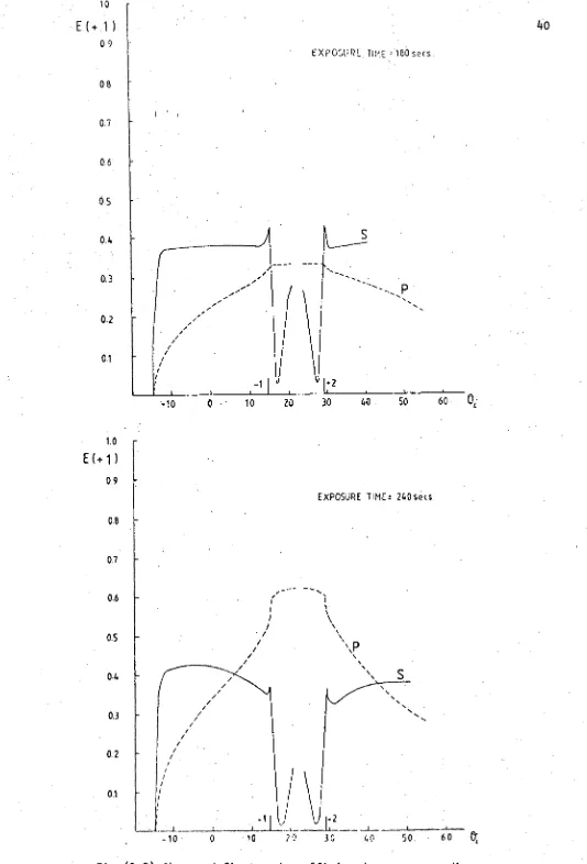
exposure of 3-6 minutes duration. The observed efficiencies
of the lth diffracted order as a function of incidence angle for
a constant wavelength of 633 nm are displayed in Fig. (2.2).
2.2.2
Inspection of groove profile
Verrill [2.14] and Palmer et al [2.15] have demonstrated
the ease with which a Rank Precision Industries Talystep measures -
directly the surface profile of a grating. A diamond stylus is
drawn across the surface of the groove and its vertical movement
is converted to an electrical signal which can be displayed as a
pen recorder trace. An example of this technique is shown in
Fig. (2.3), reproduced from Verrill's paper. This method has
the disadvantage of uncertainty in resolving the groove apex
due to the finite tip.
An alternative ihstrument, which. is used by the author, is
the electron-microscope which has both the resoTution and
depth of focus required to evaluate groove profiles. However, its
usefulness is governed by the proper presentation of specimens.
• Early work by' Anderson et al £2.2] involved the evaporation of
platinum past an asbestos whisker lying across the groove.
The resulting shadow cast by the whisker is then used to determine
the groove shape. An example.is shown in Fig. (2:4).
EXPOSURE. 1imE:=180 sec's
• • •
1.•
‘-1 1:2 r
10 20 30 40 50 60 Ot.
EXPOSURE TIME 240se(s.
-10 0
"P
,- 1 , i
10 20 30 40 50. • 60 Q -10
10
E(+ 1 ) 09
08
0.7
0.6
05
0.4
0.3
0/
01
tO E(+ 1)
0.9
0.8
0.7
0.6
0.5
0.4
0.3
0:2
0.1
• •
40
[image:47.565.14.548.27.813.2]1
—10 0 10 20 30 40 50 60
EXPOSURE TIME z 300 secs.
4
EXPOSURE TIME 360 secs.
GB
0.7
0.6
0.5
0.2 a4
0.1
0.3
\
\
\
%
/ \
/ ‘
/ .
/ \
/ \
/
y /
1 I 1
_____--- S
I
,- 10 0 10 20 30 40 50 60
(a)
Fig.(2.3) Talystep traces of single (a) andconsecutimely
Fig. (2i) An example of an electron-micrograph of a grating using asbestos whisker. Bausch and Lomb grating, blaze angle 13°54', 400mm-1 .
Although this process gives an indication'of the surface quality of the
grating, it can present a distorted view of the groove profile..
A superior method is the inspection of a thin fragment of aluminium
foil embossed with the surface relief of the grating. The
technique of sample preparation followed by the author for the
four holographic gratings mentioned previously, is described below.
With a few minor variations it is that outlined by Bennett [2.3].
Several additional layers of aluminium are evaporated onto
the grating surface. Then a piece of bare foil imprinted with the
surface profile is created by peeling off the aluminium layer with
scotch. tape. This foil is carefully wrapped over a thin U-shaped
slab of brass and attached by a few drops of a silver electroconductor
cement. The grating foil acts as a shadow mask when inserted into
the beam of the electron-microscope.
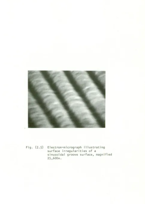
The electron-microscope allows an overall inspection of
the grating surface as revealed by Fig. (2.5) which displays the
surface irregularities of a holographic diffraction grating of
groove frequency 1180 gr/mm, at 25,000X magnification.
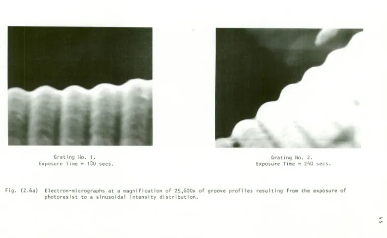
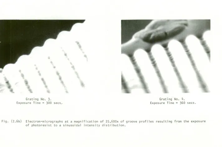
Electronmicrographs Of the groove profiles corresponding to the
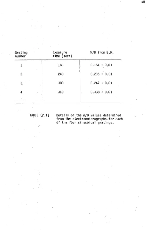
four sinusoidal gratings appear in Fig. (2.6). Table (2.1) details
the grating number, exposure time and the H/D value determined from
repeated measurements of the groove depth. Here, the term HID refers
to the ratio of the peak-to-peak depth to the period of the grating.
Examination of the grating silhouettes indicates that not
only do the size and shape of the consecutive grooves vary, but
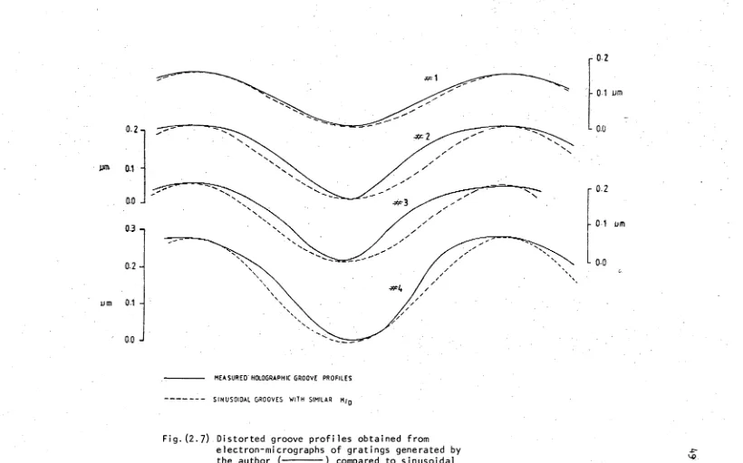
they deviate from the true sinusoidal form. This profile
deformation is magnified in Fig. (2.7) through a comparison' with
Fig. (2.5) Electron-micrograph illustrating surface irregularities of a
[image:52.566.62.546.64.745.2]Grating No. 1. Grating No. 2.
Exposure Time = 130 secs. Exposure Time = 240 secs.
[image:53.833.52.816.58.529.2]Grating No. 3. Grating No.
4.
Exposure Time = 300 secs. Exposure Time = 360 secs.
[image:54.832.66.779.52.523.2]48
Exposure H/D from E.M.
time (secs)
0.154 ± 0.01
0.235 ±0.01
0.247 ± 0.01
[image:55.567.39.533.43.816.2]0.338 ± 0.01
TABLE C2.11 Details of the H/D values determined
from the electronmicrographs for each of the four sinusoidal gratings. Grating
number
1
2
3
4
180
240
300
0.2-
pm 0.1 -
0.0 -I
0.3 -
0.2 -
um 0.1 -
0.0
MEASURED HOLOGRAPHIC GROOVE PROFILES
--- - - SINUSOIDAL GROOVES WITH SIMILAR HID
Fig. (2.7) Distorted groove profiles obtained from
[image:56.832.12.832.18.529.2]The non—linearity of the exposure-development process for the
photoresist, which is typified by rounded crests and steepened
troughs, is clearly demonstrated by each groove profile.
Furthermore, an asymmetric exposure field has produced non-symmetric
groove profiles with the degree of distortion governed by the
duration of the exposure.
The electron-microscope not only displays surface
irregularities, but enables direct measurements of the depth and
degree of distortion of the groove profile of a holographic grating
to be made. Both features significantly control the production of
high quality holographic gratings necessary to achieve the spectral
performance predicted by theory. Clearly, successful manipulation
of electron-microscope techniques represents a powerful tool in
acquiring improved holographic gratings. , A second, theoretical
approach will now be employed to gather information on the groove
profiles of the four sample gratings.
.2.2.3
Theoretical determination of groove depth
In 1977 Wilson and Botten [2.16] described a technique for
determining the groove depth of gratings having sinusoidal grooves,
whereby absolute efficiencies measured using a laser are compared
with numerical results. This method accurately determines the
groove depth provided the efficiencies are observed under conditions
where the spectral behaviour is most sensitive to variations in
groove depth. Wilson et al chose two mounts: the Littrow +1,
where the 0th order. efficiency is examined and the normal incidence
mount where a first.order beam is investigated. Measurements
are determined for both planes of polarization.
The theoretical behaviour of the efficiency as a function of groove
depth at the two important sampling angles is conveniently
summarized in Fig. (2.8). The displayed curves correspond to
sinusoidal gratings of groove frequency 1200 mm a testing
wavelength of 633 nm.
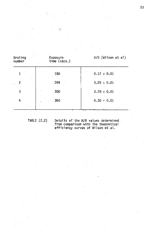
Table (2.2) outlines the grating number and the corresponding
ratio of H/D calculated from a comparison of the observed results
with those displayed in Fig. (2.8). Appearing in Fig. (2.9) are
the four observed efficiency curves and those numerically calculated
for gratings having H/D values given in the above table.
Agreement between the observed efficiency of grating #1 and the
theoretical counterpart is excellent. The only discrepancy
occuring for the S polarized light in the region of the +1 Littrow
angle. As the duration of exposure lengthens to 4 minutes the
equivalent theoretical groove depth approaches H/D = 0.25. The
previous degree of agreement is not maintained, since the observed
efficiency falls below its theoretical companion, particularly near
the -1 and +2 Wood anomalies. Although minimal, this disparity
signifies the commencement of a trend in which the spectral performance
of the observed S polarized light deteriorates with increased exposure.
For the extreme case of grating #4, correlation between theory and
observation is very poor. Obviously, the increase in groove depth
with duration of exposure is accompanied by a departure of the
spectral performance away from that exhibited by a perfect sinusoidal
groove grating. Similarly the unsymmetrical nature of the observed
efficiencies indicate asymmetric groove profiles.