An Iterative Detection Aided Irregular Convolutional Coded
Wavelet Videophone Scheme Using Reversible
Variable-Length Codes and Map Equalization
A. Q. Pham, J. Wang, L. L. Yang, and L. HanzoSchool of ECS, University of Southampton, SO17 1BJ, UK Tel: +44-23-8059 3125, Fax: +44-23-8059 4508
Email:{apq03r,jw02r,lly,lh}@ecs.soton.ac.uk, http://www-mobile.ecs.soton.ac.uk
Abstract— In this paper, we characterize the achievable performance of a wavelet encoding-based videophone system, which further compresses and protects the wavelet-based video codec’s bit-stream with the aid of Reversible Variable-Length (RVLC) codes. More specifically, the video codec uses RVLC codes for compressing and protecting the video frame header. By constrast, Irregular Convolutional Codes (IRCCs) are used for Unequal Error Protection of the video bitstream generated from the wavelet-subbands, when communicating over InterSymbol Interference (ISI) contaminated channels. At the receiver, the turbo-equalizer, the IRCC decoder and the RVLC decoder all employ the Maximum A-Posteriori (MAP) algorithm and their operations are performed in an iterative turbo-detection style. The proposed system was designed for maintaining a near-unimpaired video reconstruction quality for channel Signal-to-Noise Ratios (SNR) in excess of about 5dB, when comunicating over a five-path dispersive AWGN channel.
I. MOTIVATION
Following a period of intensive research in wireless videotelephony [1] [2], the resultant attractive services have become a commercial reality, as often seen on television. The standardized video codecs, such as for example H.264 and MPEG4, aim for removing the predictable video contents both within as well as between consecutive video frames. The inter-frame redundancy is predicted and removed with the aid of motion compensation. The residual intra-frame redundancy inherent in the Motion-Compensated Error Residual (MCER) is typically transformed to the frequency domain using Discrete Cosine Transform (DCT) and the resultant coefficients are usually further compressed using Variable Length Codes (VLC). However, as argued in the preface of [1], the design of wireless video systems hinges on numerous trade-offs, including factors such as the achievable compression ratio, the implementational complexity, the encoding delay, the robustness against transmission errors, etc. In this spirit, the British Broadcasting Corporation (BBC) developed an attractive wavelet-based design alternative, which may be employed without incurring any license-fee [3]. This codec is reminiscent of the subband-based video codecs detailed in [1] and it was also used in [4].
This wavelet video codec is capable of efficiently compressing the video source signal, while achieving a high reconstructed video quality at a low bit-rate. However, owing to the extensive employment
The financial support of the EPSRC, Swindon UK and the EU under the auspices of the PHOENIX as well as NEWCOM and Phoenix projects is gratefully acknowledged.
of VLC codes, the compressed video bitstream is sensitive to channel errors, since the codec’s variable frame length does not allow video frame synchronization to be readily re-established in the presence of transmission errors. The header information to be transmitted includes the video frame header, the Motion Vector (MV) header, and the 30 subbands’ Discrete Wavelet Transform (DWT) headers, as detailed in [4]. When aiming for low-bitrate operation, the bitrate contribution of this header information becomes quite dominant, for example about
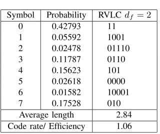
30%of the total frame size of 2000 bits. Naturally, this is the most error-sensitive segment of the encoded video frame, since no useful information can be decoded in its absence. For reasons of space economy, here we are unable to elaborate on the design of the DWT-based video codec [4], especially, since our aim here is to contrive a novel wireless transmission scheme, which is capable of enhancing the error resilience of the system. Suffice to say that the above-mentioned header segments are signalled to the decoder using so-called Reversible Variable Length Codes (RVLC), which are capable of compressing the fairly predictable header information. However, the achievable compression ratio of RVLC codes is typically lower than that of Huffman codes [5], because they have intentionally introduced inherent redundancy, which manifests itself in terms of the symmetric construction of each RVLC codeword. This property allows us to decode the VLC codewords commencing form both ends of a bit-stream in the presence of transmission errors, which increases the chances of successful VLC decoding. The corresponding VLC codeword statistics were extracted from our simulations and are portrayed in Table I. Observe that the relative frequency of ocurrence for the individual RVLC symbols in the header information is non-uniform and hence we can exploit this residual redundancy for increasing the performance of our video telephony system.
More explicitly, we were encouraged by the performance gains of the iterative detection aided unequal error protection DWT video scheme using Irregular Convolutional Codes (IRCCs) designed in [4], where the residual redundancy of the video-coded bitstream was ex-ploited for the sake of eliminating the channel-induced Inter-Symbol Interference (ISI). By contrast, in this contribution, we exploit the redundancy inherent in the header information for attaining further improved error protection. We will investigate the proposed system using EXtrinsic Information Transfer (EXIT) charts, which facilitate a better understanding of the convergence behaviour of iterative decoding.
TABLE I
RVLCUSED IN THE SIMULATION.
Symbol Probability RVLCdf = 2
0 0.42793 11
1 0.05592 1001
2 0.02478 01110
3 0.11787 0110
4 0.15623 101
5 0.02618 0000
6 0.01582 10001
7 0.17528 010
Average length 2.84 Code rate/ Efficiency 1.06
outline the schematic of the system proposed. The Soft-In Soft-Out (SISO) algorithm used by the RVLC decoder is described in Section III. In Section IV, we study the system’s EXIT characteristics based on mutual information for the sake of analysing the attainable perfor-mance of the proposed system, while in Section V our perforperfor-mance results are detailed. Finally, we conclude our discourse in Section VI.
II. SYSTEMOVERVIEW
DecoderVideo
n Outer Iterative Decoding
Channel Code
EncoderVideo
Data Frame Frame Header EncoderVLC
Packetizer DecoderIRCC PrecoderRate−1
Inner Iterative Decoding
Equalizer DecoderIRCC
SISO VLC
Depacketizer Decoder MAP Π−1
2 Π−11
Π2
Π1 Π2
Π1
bn sh
sm
ui
ˆ s0h
ˆ sh
Fig. 1. System Model: Iterative Joint Softbit RVLC decoding and UEP
The block diagram of the proposed system is shown in Fig.1. At the transmitter, the video frames are compressed by the wavelet video codec described in [4], which outputs a binary sequence sk, k = 1,2, ..., K. This sequence sk is partitioned
into two bitstreams, namely the header information (658 bits) sh, h = 1,2, ...,658, and the subband-based video information
bits sm, m = 659,660, ..., K. The header information is then
forwarded to the RVLC encoder of Fig. 1, which will be discussed in Section III, and the output of the RVLC encoderbn, n= 1,2, ..., N
is concatenated with the subband-based video bits sm, m =
659,660, ..., K, forming the resultant binary sequence ui, i =
1,2, ..., I. The packetizer maps the binary sequence ui, i =
1,2, ..., I into fixed-length packets of 2000 bits, where the ’Packet type’ bits of Fig. 2 explicitly indicate, whether the packet contains any header information. A one-bit flag is sufficient for signalling this classifier, which is repeated twice in order to allow Majority Logic Decision (MLD) at the receiver. Since one in three bits are conectable by the MLD scheme, this regime is capable of tolerating a33%channel error rate. Given that the transmitted packet contains
RVLCs, as seen in Fig. 2, its length varies slightly. The three-bit packet-type segment is followed by 9 three-bits, which are used for quantifying the exact number of RVLC bits. At the packetizer’s
output the first 700 bits ui, i = 1,2, ...,700, which constitute
the maximum length of the RVLC-encoded header information, are interleaved using the bit-interleaverΠ2of Fig. 1. The resultant binary
sequence is concatenated with the rest of the transmission packet and encoded by the same IRCCs, as detailed in [4]. The bit-interleaver
Π1 interleaves the IRCCs’output and subsequently the interleaver’s
output is encoded by the rate-1 precoder, which was shown to be capable of substantially improving the performance of iterative decoders at the cost of a low decoding complexity [6].
Packet type
Packet type frame data
frame data frame data Packet 1
Packet 2
Packet k
previous frame data RVLC data
RVLC data Packet type
Packet type
frame data Packet k+1
Fig. 2. Packetization scheme for joint RVLC-UEP decoding
At the receiver, in order to generate soft-bit information for the RVLC decoder, a turbo equalizer [13] is invoked, which consists of a Maximum A Posteriori (MAP) channel equalizer and an IRCC decoder. To be more specific, the structure of the amalgamated iterative source and channel decoding scheme seen in Fig. 1 con-sists of SISO modules, where the MAP channel equalizer and the IRCC decoder exchange extrinsic information in an iterative ’turbo-detection’ fashion, in order to form the inner iterations. Following a certain number of inner iterations, the first 700 bits A Posteri-ori Probabilities (APPs) are extracted, deinterleaved using the bit-deinterleaver Π−1
2 of Fig. 1 and forwarded to the RVLC decoder.
Using the APPs gleaned from the IRCC decoder, the RVLC decoder of Fig II estimates the packet-type bits, and depending on these bits it decides as to whether include the RVLC decoding step for the sake of decompressing the header information in interative decoding or to dispense with it. If the received packet does contain RVLC-compressed header information, the RVLC decoder generates the
extrinsic informationLs(ˆui|y)by exploiting the code constraints as
well as the non-uniform header RVLC probabilities seen in Table I, interleavesLs(ˆui|y)using the interleaver Π2 of Fig. 1 and feeds
it back to the IRCCs. This process is performed repeatedly, until the RVLC decoder generates the final estimates sˆi for the header
information bits ui, i= 1,2, ...,658 using MAP-based sequence
estimation, rather than bit-by-bit detection although using the same bit-based trellis. In order to complete the decoding of the entire received packet, the IRCCs are used for providing the estimates
ˆ
s0
i, i = 659,660, ..., K of the subband-based video bits in the
frame. Finally, the estimates ˆsi, i = 1,2, ...,658 of the header
information bitsuiare fed into the RVLC decoder of Fig. 1 in order
to reduce the header information’s error rate.
III. RVLC DECODER A. Trellis Representation
[image:2.612.313.566.177.260.2] [image:2.612.51.300.325.439.2]node of the RVLC tree of Fig. 3.a to a specific trellis state of Fig. 3.b, as detailed in [7]. The so-called root node and all its leaf nodes are mapped to the same trellis state in Fig. 3, since every leaf node becomes the start of a new legitimate RVLC codeword. The number of RVLC trellis states is equal to the number of internal nodes in the RVLC tree of Fig. 3.a plus one. Fig. 3 characterizes both the code tree and a trellis segment of our RVLC codewords C= 11,010,101,0110,1001,0000,01110,10001seen in Table I.
0
0
0 0
0
0
0 1
1 1
1
1 1 1 1
0 0
0
b. Bit−level trellis representation a. Code tree
s5
s7
s8
s6
s4
s2
s9
s10 Sn−1 Sn Sn+1
bk= 1
bk= 0
s0
s0
s0
s0
s0
s0
s0
s1 s10
s0
s10
s0
s1
s2
s3
s4
s5
s6
s7
s8
s9
s0
s1
s2
s3
s4
s5
s6
s7
s8
s9
s0
[image:3.612.50.290.166.311.2]s3
Fig. 3. Code tree and bit-level trellis representation for the RVLCs C = 11,010,101,0110,1001,0000,01110,10001
B. SISO RVLC Decoder
Based on a bit-level trellis representation of the RVLC codes, various Maximum A Posteriori (MAP) SISO RVLC decoding al-gorithms were proposed in [7], [8], [9] for uncorrelated sources. By contrast, the authors of [10] and [11] considered a first-order Markov source model for describing the correlation of the consecutive source symbols.
For the sake of decoding the header information, we invoke the SISO APP decoding approach proposed by Benedetto and Montorsi in [12], where the extrinsic information is expressed in form of the marginal distribution of the APPs associated with the trellis state transitions. Following the notation of [12], the extrinsic information is computed as follows. At time instant k, the output extrinsic information is extracted from the RVLC decoder of Fig. 1 by subtracting the input LLRPk(c|I) from the output LLRPˆk(c|O).
LLR(bk) =LLR( ˆPk(c|O))−LLR(Pk(c|I)). (1)
where we have
LLR( ˆPk(c|O)) =lnPˆk(0|O)−lnPˆk(1|O), (2)
LLR(Pk(c|I)) =lnPk(0|I)−lnPk(1|I) (3)
andPk(c|I), c∈0,1represents the input probability distribution of
the RVLCs at time instant k, while Pˆk(c|O), c ∈0,1 denotes the
output probability distribution of the RVLCs at time instantk, which is evaluated as
ˆ
Pk(c|O) =Hk X
e|c(e)=c
Ak−1(sS(e))Γk(e)Bk(sT(e)), (4)
wheree, c(e), sS(e), sT(e)represent a trellis branch, the correspond-ing decoded symbol, the startcorrespond-ing state and the terminatcorrespond-ing state of the
branche, andHk is a normalization factor that ensures maintaining
ˆ
Pk(0|O)+ ˆPk(1|O) = 1. The quantitiesAk(.)andBk(.)are obtained
with the aid of the classic forward-backward recursions of the MAP algorithm as follows [13]:
Ak(s) = X
e|sT(e)=s
Ak−1(sS(e))Γk(e), (5)
Bk(s) = X
e|sS(e)=s
Bk+1(sS(e))Γk+1(e), (6)
when using the initial values ofA0(s) = 1, BN(s) = 1for all root
states andA0(s) = 0, BN(s) = 0otherwise. The trellis transition
probabilities are computed as
Γk(e) =Pk(c(e);I)P(e), (7)
where P(e) , P[c(e), sT(e)|sS(e)] represents the a priori source
information associated with a specific trellis transition probability. All of these trellis transition probabilities are time invariant and are determined by the source distribution with the aid of the associated state transition probabilities as follows
P(c(e), sT(e)|sS(e)) =
P α∈g(sS(
e))pα P
β∈g(sS(e))pβ
, (8)
whereg(s)represents all the codeword indices associated with node sin the trellis of Fig. 3.b.
IV. EXIT CHARTANALYSIS
EXIT charts constitute simple but powerful tools contrived for designing and optimizing the performance of iterative decoding schemes. The essential philosophy of EXIT charts is that they can predict the behaviour of iterative decoding by visualizing the input/output characteristics of a single SISO decoder. To be more specific, EXIT charts observe the extrinsic information increase at the output of a decoder in response to a given a priori input. The resultant mutual information is used for describing the extrinsic information transfer characteristics of an iterative SISO decoder.
0 0.1 0.2 0.3 0.4 0.5 0.6 0.7 0.8 0.9 1
0 0.1 0.2 0.3 0.4 0.5 0.6 0.7 0.8 0.9 1
IEI IAO
IAI IEO 3dB 4dB 5dB 6dB 7dB Outer
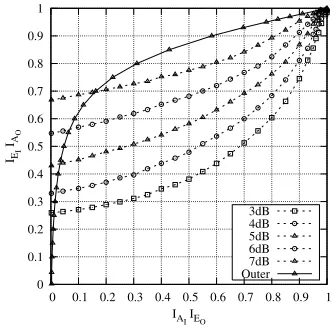
Fig. 4. EXIT chart of the proposed system, constituted by the amalgamated MAP Equalizer and IRCCs as the inner component and the RVLC having df = 2as the outer component, for transmission over a 5-path ISI channel
[image:3.612.343.509.503.669.2]while the RVLC decoder having a free distance of df = 2 as the
outer decoder. We observe from Fig. 4 that for the RVLC decoder having a free distance of df = 2, the system is unable to offer a
good performance. Figs. 5 and 6 reveal that for the three-component scheme of Fig. 1 using the RVLC decoder having a free distance of df = 2, we should carry out two inner interations, before we invoke
the RVLC decoder.
0 0.1 0.2 0.3 0.4 0.5 0.6 0.7 0.8 0.9 1
0 0.1 0.2 0.3 0.4 0.5 0.6 0.7 0.8 0.9 1
IEI IA
O
IA I IEO
3dB 4dB 5dB 6dB 7dB Outer
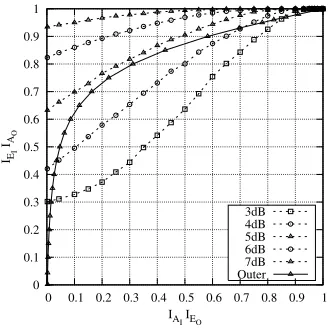
Fig. 5. EXIT chart of the proposed system, constituted by the amalgamated MAP Equalizer and IRCCs as the inner component and the RVLC having df = 2 as the outer component, as well as two inner iterations for transmission over a 5-path ISI channel
0 0.1 0.2 0.3 0.4 0.5 0.6 0.7 0.8 0.9 1
0 0.1 0.2 0.3 0.4 0.5 0.6 0.7 0.8 0.9 1
IEI IA
O
IAI IEO 3dB 4dB 5dB 6dB 7dB Outer
Fig. 6. EXIT chart of the proposed system, constituted by the amalgamated MAP Equalizer and IRCCs as the inner component and the RVLC having df = 2 as the outer component, as well as three inner iterations for transmission over a 5-path ISI channel
V. SIMULATIONRESULTS
In our simulations, a five-path dispersive channel characterized by its Channel Impulse Response (CIR) given by
h[n] = 0.227δ[n] + 0.46δ[n−1] + 0.688δ[n−2] +0.46δ[n−3] + 0.227δ[n−4] (9) was used, which imposed severe Inter-Symbol Interference (ISI) [14]. The RVLC encoder of Table I was employed. The videophone
system’s parameters are summarized in Table II. The video-sequence scanning rate was 10 frames/s and the average encoded video frame size was approximately 2000 bits, yielding a video-encoded bitrate of about 20kbit/s. A video-packet size of 2000 bits was used, because the majority of the inter-frame encoded pictures resulted in an encoded packet size below 2000 bits. The resultant 2000-bit video packets were IRCC-encoded at a total average code-rate of about 0.5, yielding a 4000-bit frame, which was interleaved by the 4000-bit-memory inner interleaver. The IRCC scheme [16],[4] consists of a set of subcodes having coding rates of[0.35 0.45 0.5 0.55 0.6 0.8], which encode [34% 1.3% 4.8% 22% 6.5% 31%] of the input data bits,
respectively. Both the Bit Error Rate (BER) and Frame Header Error
TABLE II
THE PARAMETERS OF THE PROPOSED VIDEOPHONE SCHEME.
The system parameters
average encoded frame length 2000 bits/video frame
Packet size 2000 bits
Packet type flag 3 bits
RVLC header size 27 bits
Everage IRCC Code rate 1/2 Inner bit-Interleaver Π1 4000 bits
Outer bit-InterleaverΠ2 700 bits
No. of Outer iterations 8 No. of inner iterations 2
Outer mother-code polynomials g0= 1 +D+D2+D4
g1= 1 +D3+D4
Constraint length 5
Video frame-rate 10 frames/sec Video bit-rate 20kbits/sec IRCC encoded bit-rate 40kbits/sec
Rate (FHER) were evaluated for the original UEP scheme detailed in [4] and in Fig. 1, respectively, when transmitting the DWT-encoded video bitstream over the five-path ISI channel of Eq. 9. As seen in Fig. 8, the proposed scheme is capable of attaining an infinitesimally low FHER for channel Signal-to-Noise Ratios (SNRs) in excess of about 5dB for transmission over a five-path dispersive AWGN channel, when using eight outer iterations between the RVLC decoder and the IRCC decoder, as well as three inner iterations between the MAP equalizer and the IRCC decoder.
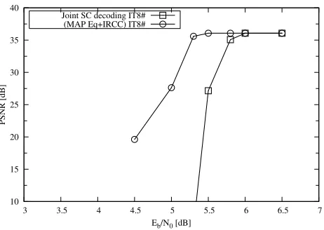
[image:4.612.82.246.157.322.2]In conclusion, it is worth noting that the DWT based video bits are less sensitive to transmission errors than the header bits. In order to characterize the entire system’s attainable video performance, in Fig. 9 we plotted the video Peak-Signal-to-Noise Ratio (PSNR) as a function of the channel SNR.
VI. CONCLUSIONS ANDFUTUREWORK
[image:4.612.81.246.402.569.2]10-6 10-5 10-4 10-3 10-2 10-1 100
3 4 5 6
BER
Eb/N0 [dB]
Proposed system,InnerIT2#,OuterIT8# MAP Equalizer+IRCC,IT8# Proposed system,InnerIT1#,OuterIT8#
Fig. 7. BER performance of the combined transceiver, when communicating over the five-path ISI channel of Eq. 9
10-4 10-3 10-2
10-1 100
3 4 5 6
FHER
Eb/N0 [dB]
[image:5.612.53.294.69.230.2]Joint SC decoding IT4# Joint SC decoding IT8# (MAP Eq +IRCC) IT8#
Fig. 8. FHER performance of the combined transceiver, when communicating over the five-path ISI channel of Eq. 9
10 15 20 25 30 35 40
3 3.5 4 4.5 5 5.5 6 6.5 7
PSNR [dB]
Eb/N0 [dB] Joint SC decoding IT8#
(MAP Eq+IRCC) IT8#
Fig. 9. Comparison of the achievable video PSNR using both the UEP scheme detailed in [4] and the proposed RVLC-aided system. The system parameters are summarized in Table II.
REFERENCES
[1] L. Hanzo, P. J. Cherriman, and J. Streit, “Wireless Video Communi-cations: Second to Third Generation System and Beyond,” Piscataway, NJ:IEEE Press, 2001.
[2] S. X. Ng, J. Y. Chung, L. Hanzo, ”Turbo-detected unequal protection MPEG-4 wireless video telephony using trellis coded modulation and space-time trellis coding”, IEE Proceedings on Communications, Volume 152, Issue 6, 9 Dec. 2005 pp:1116 - 1124 .
[3] Sourceforge website: http://sourceforge.net/projects/dirac
[4] A. Q. Pham, J. Wang, L. L. Yang, and L. Hanzo, ”Joint Source-Channel Decoding for An Iterative Detection Aided Unequal Error Protection Wavelet Video Scheme Using Irregular Convolutional Codes ”, 2006 IEEE 63rd Vehicular Technology Conference, Melbourne, Australia, 7-10 May 2006.
[5] J. Wang, L. L. Yang, and L. Hanzo, ”Iterative construction of reversible variable-length codes and variable-length error-correcting codes”, Com-munications Letters, IEEE, Volume 8, Issue 11, Nov. 2004 pp:671-673. [6] D. Divsalar, S. Dolinar, F. Pollara, ”Serial concatenated trellis coded modulation with rate-1 inner code”, IEEE Global Telecommunications Conference, 2000, GLOBECOM ’00 , Volume 2, 27 Nov.-1 Dec. 2000 pp:777-782.
[7] V. B. Balakirsky, ”Joint source-channel coding with variable length codes”, Proceedings of the IEEE Symposium on Information Theory, Germany, 29 June-4 July, 1997, pp. 419.
[8] J. Wang, L. L. Yang, L. Hanzo, ”Iterative channel equalization, channel decoding and source decoding” , in Procedings of Vehicular Technology Conference, 2005, VTC 2005-Spring, Volume 1, 30 May-1 June 2005 pp: 518 - 522.
[9] R. Bauer and J. Hagenauer, ”Symbol-by-symbol MAP decoding of variable length codes”, in Procedings of ITG Conference Source and Channel Coding, Munich, Germany, Jan 2000, pp: 111-116.
[10] M. Park and D. J. Miller, ”Joint source-channel decoding for variable-length encoded data by exact and approximate MAP sequence estima-tion”, IEEE Transactions on Communications, vol. 48, no. 1, Jan. 2000, pp: 1-6.
[11] R. Thobaben, J. Kliewer, ”Low-Complexity Iterative Joint Source-Channel Decoding for Variable-Length Encoded Markov Sources”, IEEE Transactions on Communications,Volume 53, Issue 12, Dec. 2005 pp. 2054-2064.
[12] S. Benedetto, D. Divsalar, G. Montorsi, F. Pollara, ”A input soft-output APP module for iterative decoding of concatenated codes”, Communications Letters, IEEE Volume 1, Issue 1, Jan. 1997 pp. 22-24.
[13] L. Hanzo and T. H. Liew and B. L. Yeap,”Turbo coding, turbo equal-isation and space-time coding for transmission over fading channels”, IEEE Press, 2002.
[14] J. Proakis,Digital Communications. New York: McGraw-Hill, 4th ed., 2001.
[15] I. Lee, ”The effect of precoder on serially concatenated coding systems with an ISI channel”,IEEE Transactions on Communications, vol. 49, pp. 1168–1175, July 2001.
[16] M. Tuchler, and J. Hagenauer, ”EXIT charts of irregular codes,” in
Pro-ceedings of Conference on Information Science and Systems, Princeton
[image:5.612.52.294.300.461.2] [image:5.612.62.293.529.693.2]