OPTIMIZATION OF VISION-GUIDED MOBILE ROBOT
NAVIGATION USING DUAL CAMERA
This report is submitted in accordance with requirement of the University Teknikal Malaysia Melaka (UTeM) for the Bachelor Degree of Manufacturing Engineering
(Robotics and Automation) (Hons.)
by
MUHAMMAD FAKHRURAZI BIN MOHD HALIT B051310172
940128-14-5023
FACULTY OF MANUFACTURING ENGINEERING
DECLARATION
I hereby, declared this report entitled “Optimization of Vision-Guided Mobile Robot Navigation using Dual Camera” is the results of my own research except as cited in
reference.
Signature :……….
Author’s Name : MUHAMMAD FAKHRURAZI BIN MOHD HALIT
APPROVAL
This report is submitted to the Faculty of Manufacturing Engineering of Universiti Teknikal Malaysia Melaka as a partial fulfilment of the requirements for the degree
of Bachelor of Manufacturing Engineering (Robotics and Automation)(Hons.).
The members of the supervisory committee are as follows:
………
UNIVERSITI TEKNIKAL MALAYSIA MELAKA
BORANG PENGESAHAN STATUS LAPORAN PROJEK SARJANA MUDA
TAJUK: OPTIMIZATION OF VISION-GUIDED MOBILE ROBOT NAVIGATION USING DUAL CAMERA
SESI PENGAJIAN: 2016/2017 Semester 2
Saya MUHAMMAD FAKHRURAZI BIN MOHD HALIT
mengaku membenarkan Laporan PSM ini disimpan di Perpustakaan Universiti Teknikal Malaysia Melaka (UTeM) dengan syarat-syarat kegunaan seperti berikut:
1. Laporan PSM adalah hak milik Universiti Teknikal Malaysia Melaka dan penulis.
2. Perpustakaan Universiti Teknikal Malaysia Melaka dibenarkan membuat salinan
untuk tujuan pengajian sahaja dengan izin penulis.
3. Perpustakaan dibenarkan membuat salinan laporan PSM ini sebagai bahan
pertukaran antara institusi pengajian tinggi.
4. **Sila tandakan (√)
SULIT
TERHAD
TIDAK TERHAD
(Mengandungi maklumat yang berdarjah keselamatan atau kepentingan Malaysiasebagaimana yang termaktub dalam AKTA RAHSIA RASMI 1972)
(Mengandungi maklumat TERHAD yang telah ditentukan oleh organisasi/badan di mana penyelidikan dijalankan)
Alamat Tetap:
NO 29 JALAN USJ 2/2G, 47600 SUBANG JAYA, SELANGOR DARUL EHSAN
Tarikh: _________________________
Disahkan oleh:
Cop Rasmi:
i
ABSTRACT
ii
ABSTRAK
iii
DEDICATION
Specially dedicate to my beloved mother, my beloved father, my beloved family, supervisor,
lecturer, seniors and friends who have guided and inspired me through my journey in
iv
ACKNOWLEDGMENT
v
TABLE OF CONTENT
Abstract i
Abstrak ii
Dedication iii
Acknowledgment iv
Table of Contents v List of Tables viii
List of Figures ix
List of Abbreviations xi
List of Symbols xiii
CHAPTER 1: INTRODUCTION 1.1 Background of Study 1
1.2 Problem Statement 2
1.3 Objectives 3 1.4 Scope of Study 3 CHAPTER 2: LITERATURE REVIEW 2.1 Introduction 4
2.2 Vision System Navigation 4
vi
2.2.2 Stereo Vision 6
2.2.3 Multiple Vision 7 2.3 Mobile Robot 8
2.3.1 History 9
2.3.2 Architecture and Specifications 10
2.3.2.1 Control Scheme 11
2.3.2.2 Navigation 12
2.3.2.3 Communication 13
2.3.2.4 Mechanical Structure 14
2.3 Arduino 15
CHAPTER 3: METHODOLOGY 3.1 Flow Chart of the Project 16
3.2 Planning of Project 18
3.3 Development of Project 18
3.3.1 Hardware Design 18
3.3.2 Software Design 26
3.4 Experimental Plan 28
3.4.1 Layout 28
3.4.2 Variable to be Measured 30
3.5 Conclusion 30
vii
4.1.1 Layout 1 33
4.1.2 Layout 2 34
4.1.3 Layout 3 35
4.2 Comparing Vision 36
4.2.1 Camera View in PixyMon 37
4.2.2 Layout 3 Experiment 38
4.3 Sustainability 40
4.4 Conclusion 40
CHAPTER 5: CONCLUSION AND RECOMMENDATION 5.1 Conclusion 41
5.2 Recommendation for Future Work 42
REFERENCES 43
viii
LIST OF TABLES
3.1 Bill of material 21
3.2 Example of collected data 30
4.1 Time taken for single camera 33
4.2 Time taken for dual camera 33
4.3 Time taken for single camera 34
4.4 Time taken for dual camera 34
4.5 Time taken for single camera 35
ix
LIST OF FIGURES
1.1 Developed Arduino Mobile Robot 2
2.1 CMUcam5 (Pixy) 6 2.2 An example of robot task 8 2.3 Shakey 1960 9
2.4 Tee Toddler 1976 10
2.5 The general control scheme 11
2.6 Bipedal walking 14
2.7 Pin for control board 18
2.8 Pin for motor board 19
2.9 Control Board 21
2.10 Motor Board 22
3.1 Flow Chart of project 17
3.2 AGV mobile robot in Solidwork 19
3.3 Arduino Uno 20
3.4 Top view of mobile robot 22
3.5 Connection of Standard- and Fast-mode devices to the I2C-bus 23
3.6 Fritzing Sketch of Electronic Parts of Mobile Robot 23
x
3.8 Changing the connection type (data out port) 24
3.9 Connection pins reference 25
3.10 Information of each detected object 25
3.11 Configure paramerter in PixyMon software 26
3.12 Sample code 27
3.13 Colour detection in PixyMon 27
3.14 Layout 1 28
3.15 Layout 2 29
xi
LIST OF ABBREVIATIONS
3D - Three Dimension
AC - Alternate Current
AGV - Automatic Guided Vehicle
CMU - Carnegie Mellon University
COM - Component Object Model
CPU - Central Processing Unit
DC - Direct Current
DSP - Digital Signal Processors
EEPROM - Electrically Erasable Programmable Read-Only Memory
FAT - File Allocation Table
FPGA - Field-Programmable Gate Arrays
fps - Frames Per Second
I2C - Inter-Integrated Circuit
ICSP - In-Circuit Serial Programming
IDE - Integrated Development Environment
LCD - Liquid Crystal Display
LED - Light-Emitting Diode
MISO - Master In Slave Out
MOSI - Master Out Slave In
xii
PWM - Pulse width modulation
SCK - Serial Clock
SCL - Serial Clock
SD - Secure Digital
SDA - Serial Data
SLAM - Simultaneously Localization and Mapping
SPI - Serial Peripheral Interface
SRI - Standford Research Institute
SS - Slave Select
UART - Universal Asynchronous Receiver/Transmitter
xiii
LIST OF SYMBOLS
𝑥̅ - average
KB - kilobyte
mA - miliAmpere
MHz - mega hertz
mm - milimeter
V - volt
1
CHAPTER 1
INTRODUCTION
1.1 Background of study
Robot is an electromechanical machine that is commanded by a computer program or electronic circuitry. There were many types of robot such as mobile robot, medical robot, robot arm, service robot, educational robot, industrial robot and other. All those robots were controlled and programmed based on their function.
Mobile robot is an automatic machine. It is capable to move from one point to another point and are not set to one physical condition. Mobile robots can be autonomous mean they are competent of navigate an uncontrolled environment without the need for physical or electro-mechanical guidance devices. These mobile robots are widely used and become more common place in commercial and industrial settings.
2
Previous project for this topic was done by senior student which he developed and optimize the vision system for Arduino Robot. The development that has been made was attaching the camera CMUcam5 (Pixy) to the robot. The camera used as vision to mobile robot to follow line and obstacle avoidance rather than using infrared sensor and ultrasonic sensor. Besides, this new development also can detect colour image and path switching. The comparison of efficiency between vision sensor (camera) and basic sensor (infrared sensor and ultrasonic sensor) is made. The comparison made by taking the average time taken for robot to perform the task.
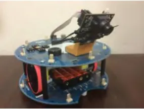
[image:19.595.269.412.392.500.2]The new development of this project will continue by optimize by propose the efficient vision system to the mobile robot. Generally, this mobile robot will detect object in indoor environment with wide view of vision system. Two units of camera CMUcam5 (Pixy) will attach to the mobile robot to wider the vision system and navigate this mobile robot.
Figure 1.1: Developed Arduino Mobile Robot
1.2 Problem Statement
3
i. Arduino Robot has limited ability of navigation system. ii. The vision systems for the mobile robot are basic and narrow
iii. An autonomous mobile robot navigation requires better vision system to perform tasks accurately.
1.3 Objectives
The objectives of this study are:
i. To propose efficient vision system using dual camera on a mobile robot for navigation.
ii. To validate the proposed vision-guided mobile robot for navigation and object detection.
1.4 Scope of Study
i. Purpose the new development of vision-guided system for mobile robot based on ATmega328P microcontroller.
ii. Study and develop the programming code to navigate the mobile robot using Arduino IDE software and PixyMon software.
4
CHAPTER 2
LITERATURE REVIEW
2.1 Introduction
This chapter provide some information knowledge about the mobile robot and other components that related to my case study. Mostly, all the information and knowledge were obtained from the articles, journals, books and other related sources. There were some facts and working principles been explained in this literature review.
2.2 Vision System Navigation
5
Vision system navigation is a system used to visualize the data from vision system to help the mobile robot navigates itself into the environment. A mobile robot can be navigated by using camera or vision sensor as a vision system. Camera used can detect the object or interpret image from the environment. When the image is detected, the mobile robot will localize itself means know it’s current position. Basically, if the camera detected the object or any other information, mobile robot will decide the movement whether to avoid or move forward. The movement of mobile robot is automated and programmed by the user.
2.2.1 Mono Vision
Mono vision image is captured by monocular camera which is one of the most frequently used ones, due to its being cheap in cost and rich in information (L. Xiao et. al., 2016). Using mono vision camera can detect the length and breadth of the obstacles (S. Mahajan et. al., 2013). Mono vision has the advantage of a lower image processing time. However, this mono vision with ingle camera makes it complex as no depth information is available to avoid obstacles (S.G Charan et. al., 2015). Object detection in varied real-time scenarios is a very difficult task. Object detection in irregular environment and varied angle of view is the problem to be settled.
6
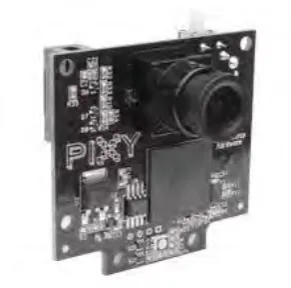
[image:23.595.232.378.192.336.2]several interfaces: SPI, I2C and UART, digital or analog output at 50 frames per second. The native resolution the Pixy’s image sensor is 1280x800, but for higher frame rate of up to 50 frames/sec, and lower CPU and memory requirements the vision system actually uses 320 x 200 pixel resolution.
Figure 2.1: CMUcam5 (Pixy) (cmucam.org)
2.2.2 Stereo Vision
7
generation, to visual hull reconstruction, which commonly need to be done in real-time, i.e., at frame rates of 15 or 30 frames per second (fps). Raw or pre-processed stereo image representations designed for human analysis and interpretation are the information that generated oftentimes.
Besides, this type of vision also has some problem due to noise. Noise due to stereo imbalanced is a serious problem (Murray et. al., 2000). Indoors scenes containing mirror-like surfaces, repetitive patterns, and time-varying light sources can cause errors that almost uniformly distributed across the imparity range of the stereo system. These imbalanced could be reduced with validation through comparing left-to-right and right-to-left best matches (P. Fua, 1993), the validation approaches by developing the number of cameras in a multi baseline system (T. Kanade et. al., 1996). However, even with a trinocular stereo system, these errors will appear. The error affect the quality of the map drastically and appear as “spikes” in the disparity image. Moreover, stereo vision demands a lot of processing time because it has complex task which is involves finding correspondence between images (M.I Arenado et. al., 2014).
2.2.3 Multiple Vision