UNIVERSTI TEKNIKAL MALAYSIA MELAKA
SYSTEM RESPONSE FOR LIGHTWEIGHT ROBOT ARM
This report is submitted in accordance with requirement of the Universiti Teknikal Malaysia Melaka (UTeM) for the Bachelor Degree of Manufacturing Engineering
(Robotics and Automation) (Hons.)
by
MOHAMMAD TAQIYUDDIN BIN MOHD RAZALI B051210098
920924-03-6305
DECLARATION
I hereby, declared this report entitled “System Response for Lightweight Robot Arm” is the results of my own research except as cited in reference.
Signature : ………..
Author’s Name : Mohammad Taqiyuddin bin Mohd Razali
APPROVAL
This report is submitted to the Faculty of Manufacturing Engineering of UTeM as a partial fulfillment of the requirements for the degree of Bachelor of Manufacturing Engineering (Robotics and Automation) (Hons.). The member of the supervisory is as follow:
i
ABSTRAK
ii
ABSTRACT
This report presents the work done on system response for lightweight robot arm (ITRobot). The research works on the identification of the lightweight robot arm models found in the literature are very limited. Most researchers study on the heavyweight types of robot arm that commonly applied in the manufacturing industry. New application as well as new performance in terms of high speed, high stability and high precision can be obtained by designing a system with good transient response properties. System response is one of the main elements in system identification techniques. A suitable instrument and analytical procedure is used to obtain the input and output of system. The objectives of this project are to determine the frequency response of the system for lightweight robot arm and to analyse the behavior and characteristics of lightweight robot arm using Fast Fourier Transform (FFT). The results for simulation are obtained by using SimMechanics toolbox that is available in MATLAB software while for experimental analysis is using the robot hardware which is lightweight robot arm. The analysis for both experiments is based on gain margin, phase margin, and FFT. According to the rule of thumb, gain margin is 4-10 dB while phase margin is 300-900. The results were
iii
DEDICATION
To my beloved parents,
iv
ACKNOWLEDGEMENT
First and foremost, all praise to The Almighty, who made this accomplishment possible. I seek His mercy, favor and forgiveness.
I would like to express the deepest appreciation and thanks to my great supervisor, Puan Nur Aidawaty Rafan who give a full belief, encouragement, guidance and persistent help throughout this project. Without her continued support, this research would not have been possible.
I would like to thank, Miss Madihah bt Haji Maharof and Mr Chiew Tsung Heng for sharing the knowledge and patiently teach me about the MATLAB software and how to perform a system identification technique. Also thanks to my fellow friends who gave a supportive and suggestion idea that help me a lot in this project. Last but not least, I would like to thanks and love to my parent, Mohd Razali bin Awang and Amikalsom binti Hamzah for the moral support and encouragement to complete this project.
v
TABLE OF CONTENT
Declaration Approval
Abstrak i
Abstract ii
Dedication iii
Acknowledgement iv
Table of Content v
List of Tables viii
List of Figures ix
List Abbreviations xi
CHAPTER 1: INTRODUCTION
1.1 Background 1
1.2 Problem statement 4
1.3 Objective 5
1.4 Scope of project 5
1.5 Significance 6
1.6 Outline 6
CHAPTER 2: LITERATURE REVIEW
2.1 Introduction 7
2.2 Type and application of robot 7
2.3 System identification 14
vi CHAPTER 3: METHODOLOGY
3.1 Introduction 18
3.2 Overview 18
3.3 Project Implementation 19
3.3.1 Literature Study 20
3.3.2 Identification of Frequency Response and bandwidth of system 20 3.3.3 Numerical and Experimental Validation 26 3.3.4 Data Analysis and Report Writing 30
3.4 Gantt Chart 33
3.5 Summary 34
CHAPTER 4: DESIGN
4.1 Introduction 35
4.2 Offline and Online Experiment 36
4.3 Summary 46
CHAPTER 5: RESULT AND DISCUSSION
5.1 Introduction 47
5.2 Result and Discussion 47
5.2.1 Offline Experiment (Numerical) 47 5.2.2 Online Experiment (Experimental) 50
5.3 Summary 57
CHAPTER 6: CONCLUSION AND RECOMMENDATION
6.1 Conclusion 58
6.2 Recommendation 59
vii
REFERENCE 61
APPENDICES
A PSM 1 Gantt chart 66
viii
LIST OF TABLES
2.1 Table of comparison of each type of robot configurations 10
3.1 Table of instrument list 20
3.2 Table of joints names 22
ix
LIST OF FIGURES
1.1 Lightweight Robot Arm 2
2.1 Basic configurations of Robot 9
2.2 Basic robot motion 9
2.3 PANDI-2 13
2.4 PANDI-1 13
2.5 A simple closed loop system 14
2.6 Algorithm for Modeling and System Identification 15
2.7 Block diagram of overall system 17
3.1 Flow chart of project development 19 3.2 Lightweight Robot Arm (ITRobot) 22
3.3 Degree-Of-Freedom 22
3.4 Base DC Servo Motor 23
3.5 Voltage Regulator 23
3.6 Driver Box 24
3.7 Micro Box 25
3.8 System Identification Block Diagram 26 3.9 Flowchart for System Identification 28 3.10 Fast Fourier Transform (FFT) Plot 30
3.11 Bode diagram 31
3.12 Gantt Chart Overall 33
4.1 Block diagram of overall system 35
4.2 ITRobot Open Loop 37
4.3 ITRobot Close Loop 38
4.4 Robot Controller Block 38
4.5 Before Optimization 39
4.6 After Optimization 40
4.7 Final Simulation Model 41
4.8 Robot Dynamic Block 41
4.9 Robot Hardware 43
x
xi
LIST OF ABBREVIATIONS
CIM - Computer Integrated Manufacturing DOF - Degree-Of-Freedom
FPE - Akaike’s Final Prediction FFT - Fast Fourier Transform LSE - Least Square Estimation FFS - Finite Fourier Series
FKP - Fakulti Kejuruteraan Pembuatan UTeM - Universiti Teknikal Malaysia Melaka DAQ - Data Acquisitions System
DC - Direct Current SI - System Identification
FRF - Frequency Response Function
FDIDENT - Frequency Domain System Identification Toolbox SISO - Single-Input/Single-Output
PID - Proportional-Integral-Derivative PSM - Projek Sarjana Muda
RAM - Random Access Memory PWM - Pulse Width Modulation IO - Input/Output
1
CHAPTER 1
INTRODUCTION
1.1 Background
Robots are mostly used to replace human power such in applications that are dangerous, high precision or in routine and repeated works. They actually can do a better job compared to human. Robot arm is one of the type of robot which works similarly to a human arm. According to Rehiara et al. (2010), a robot arm or also called a manipulator is composed of a set of joints separated in space by the arm links, and it looks like human’s wrist and elbow. In most robotic applications, robot can be subjected to a variety of external forces such as due to the disturbances, interaction with work piece, and collision with obstacles. The performance of the robot controller in this type of situation is critical to the success of the overall operation. Due to imprecision, it is difficult to control the robot motion to do an appropriate job perfectly. The imprecision can happen during the robot motion or operation and it might be caused by its own structure on the control algorithm. The dynamic parameters of the robot also cannot be brought together into the robot model because of the imprecision. In order to get a good robot model, the knowledge of the robot parameter values should be in line to the robot system in detail.
2
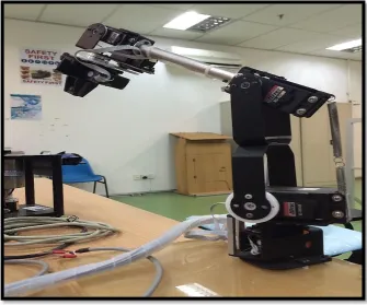
[image:17.595.149.485.156.435.2]arm. Lightweight robot arm actually used in industrial such as for pick-and-place, assembly, and packaging applications. Figure 1.1 shows the lightweight robot arm that used in this project.
Figure 1.1: Lightweight Robot Arm
System or process identification is the field of mathematical modeling systems from test or experimental data. According to Zhu (2001), the input-output data are usually collected from an identification test or experiment that is designed to make measured data maximally informative about the system properties. According to Mikles and Fikar (2007), there are several procedures to estimate transfer function of the system. The steps in conducting the system identification are as follows:
i. The determination of the model structure that usually comes from the empirical experience about the process or information from some basic experiments.
3
iii. The model verification should consider some of the criteria. A suitable model should agree with the experimental data, it should describe the process accurately, and it should meet the purpose in which it was obtained for. Besides, it can be verified whether the parameters obtained are within the physical limits and the possibility to reduce the model and to compare it with the original model to see if a simpler model suffices.
There are three ways to define a mathematical model in system identification that is white box modeling, grey box modeling and black box modeling. All the types are different with each other in term of the parameters status and the way to get the model. In order to get a good model, a model should be validated by using the suitable software. MATLAB System Identification Toolbox has provided two kinds of model validation that is by using the residual analysis plots or Akaike’s Final Prediction (FPE) criterion. According to Eric and Simon (2004), the Akaike information criterion is a popular method for comparing the adequacy of multiple, possibly non-nested models. Both of the validation types provided by the software are used for a different way. Lennart Ljung (2010) states that the residual analysis plot types can be used for either time domain or frequency domain input-output data and consist of whiteness test and independent test meanwhile Akaike’s Final Prediction (FPE) provide a measure of model quality by simulating the situation where the model is tested on different data set.
4
and neural network for control 3-DOF robot manipulator, (Rasit, 2004) presented a neural network for solving 3-joint robot inverse kinematics, and (Toshio, 2005) introduced a neural network in case is of robotic arm on-line learning.
1.2 Problem statement
Recently, robot manufacturers have increased development effort towards new application such as machining, laser welding, laser cutting and multi-robot collaboration which puts new forward performance requirements on robots. The requirements here which mean high speed, high stability and high precision, can be satisfied by involving advances model-based control schemes. The previous system response that developed do not meet the new performance requirement for applications nowadays.
5
The transfer function of a system is the relationship of the systems output to its input, represented in the complex Laplace domain. Transfer function is a representation of the linear time invariant dynamic system that fully describes a control system where the order, type and frequency response can all be taken from this specific function. The Bode response plots show the stability of the system when the loop is closed. So, the system identification technique will be applied to determine the system response for the system. Lightweight robot arm that is used for simulation and analysis. Validation and verification of the results is to ensure that the system response obtained viable and practically feasible.
1.3 Objective
The objectives of this study are:
i. To determine the frequency response of the system for lightweight robot arm. ii. To analyse the behavior and characteristics of lightweight robot arm using
Fast Fourier Transform (FFT).
1.4 Scope of Project
The scopes of the project are as follows:
i. Experimental work on Lightweight Robot Arm is conducted without load ii. Numerical and experimental work is by using MATLAB/Simulink software iii. Analyse frequency response of system using SimMechanics.
6
1.5 Significance
The findings of this study will contribute to the benefit of society considering that system identification plays an important role in science and technologies nowadays. The benefits from this research can be in term of industry and knowledge. For industries aspect, the demands on the high and new performance of applications can be achieved successfully if the good system identification is conducted to a system. As a result, a next level of applications for instance material handling, machining and surgery can be implemented broadly. The theory and methodology in this studies can be used for further research that related to the control system applications. Thus, a new method to conduct a system identification can be proposed perhaps by the next researcher.
1.6 Outline
This report consist of five main chapters that are introduction, literature review, methodology, design, and result and discussion.
i. Chapter 1 consists of problem statement, objective, scope of project, and significance that clearly stated.
ii. Chapter 2 covers literature review of a journal that related to field in order to identify studies, models, and case studies that supporting this project.
iii. Chapter 3 is a methodology which compile all the idea on how this project conducted and supported with the overview, flowchart of the project, validation and analysis technique and Gantt chart for this project.
iv. Chapter 4 is designs of model for block diagram that related to the robot system for both experiment which offline and online that used in this project. v. Chapter 5 contains of result and discussion where result that obtained from
experiment are briefly discussed and explained supported with some analysis according to the objective that need to be achieved.
7
CHAPTER 2
LITERATURE REVIEW
2.1 Introduction
This chapter covers the literature review that is divided into two section. The first section is the type of robot and their applications in the industrial field. This section covers on the lightweight robot arm supported with the characteristics and structures of the lightweight robot arm. Furthermore, the next section is system analysis which discussed the function and technique that commonly used by researchers to obtain system response of a system. System response leads to the variety of application and at once enhance the performance of the system.
2.2 Type and Application of Robot
Robots utilised for automation in a way that humans have specified. They are built to serve the people. This shows robot as a nice machine serving humans is however, not shared by everyone. According to Asimov (1950), in order to make the robots behave more nicely, the robot should obey “The three laws of robotics”.
i. A robot may not injure a human being or, through inaction, allow a human being come to harm.
ii. A robot must obey orders given it by human beings except where such orders would conflict the First Law.
8
An industrial robot is a programmable, multi-functional manipulator designed to move materials, parts, tools, or special devices trough variable programmed motions for the performance of a variety of tasks. Robots are mostly used to replace workers in such dangerous, high precision or in routine and repeated works where it’s often do a better job than human according to Rehiara et al. (2010).
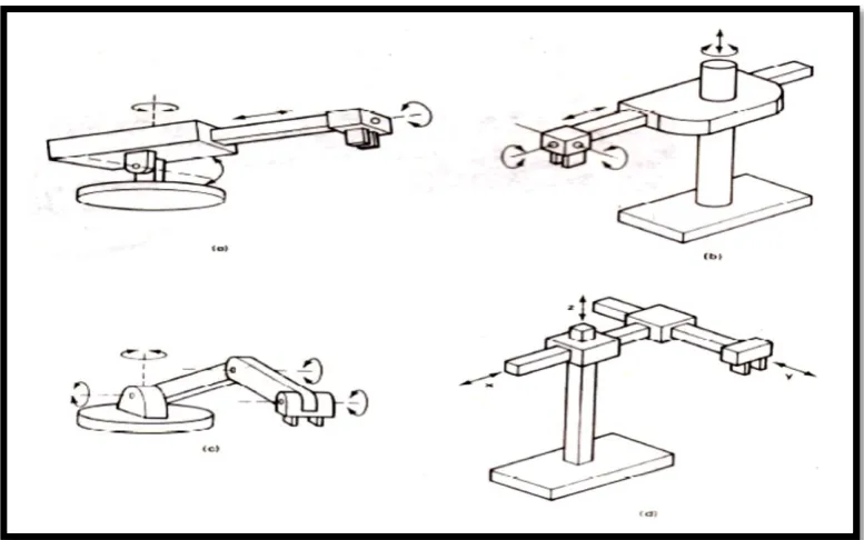
There are several types of robot in terms of shapes and sizes. This happen because of varies of the tasks that need to be performed by the robots to replace a human power. They are capable of various arm manipulation and they possess different motion systems. The classification is based on the physical configuration of the robot itself. Four basic configurations are identified with most of the commercially available industrial robots are:
i. Cartesian configurations: It consists of three orthogonal slides that parallel to the x, y and z axes of the Cartesian coordinate system. By appropriate movements of these slides, the robot is capable of moving its arm at any point within its three dimensional rectangularly spaced work space.
ii. Cylindrical configurations: Robot body is a vertical column that swivels about vertical axis. The arm consists of several orthogonal slides which allow the arm to be moved up or down and in and out with respect to the body. iii. Polar configurations: Also called “spherical” coordinate because the
workspace within which it can move its arm is a partial sphere. The robot has a rotary base and a pivot that can be used to raise and lower a telescoping arm.
9
[image:24.595.122.513.113.355.2]Entire basic configurations are illustrated in the Figure 2.1 and Figure 2.2 below.
Figure 2.1: Basic configurations of Robot (Source:
http://elearning.vtu.ac.in/11/enotes/CompIntManf/unit8-nan.pdf)
Figure 2.2: Basic Robot Motion (Source:
[image:24.595.123.512.446.689.2]