I
I hereby declare that I have read through this report and found that is comply the partial fulfillment for awarding the degree of Bachelor of Electrical Engineering (Industrial Power)
I
PERFORMANCE EVALUATION OF ACTIVE AND PASSIVE FILTERS FOR HARMONIC REDUCTION IN ELECTRICAL DISTRIBUTION SYSTEM BASED
ON SYNCHRONOUS REFERENCE FRAME (SRF)
MUHAMMAD ASYRAF BIN MOHD HANAFI
A project report submitted in partial fulfilment of the requirement for the award of Bachelor of Electrical Engineering
(Industrial Power)
Faculty of Electrical Engineering
UNIVERSITI TEKNIKAL MALAYSIA MELAKA
II
I declare that the project report entitled “Small Wind Energy Converter” is the results from my own research except as cited in the references.
III
I
ACKNOWLEDGEMENT
In the name of Allah, the Most Beneficent and The Most Merciful. It is a deepest sense gratitude of the Almighty that give me strengh and ability to complete this Final Year Project report.
A special gratitude I give to my final year project supervisor , Prof. Madya IR DR Rosli Bin Omar , whose give me a valuable guidance and support and helped me to coordinate my project especially in writing this report.
A special thanks goes to my family for their moral support to me in the process to complete this project. Besides that, I would also like to acknowledge with much appreciation to all my friends who help me in order to complete my Final Year Project.
II
ABSTRACT
The wide use of controlled power appliances such as personal computer, switch mode power supply, adjustable stepped drive inject a significance harmonic distortion in power system. These harmonic cause an increase in level of rms supply current which results an increase of power loss, heating of equipment and also deteriorates the quality of power. Passive filter have been used to suppress harmonics current conventionally. This kind of filter cannot modify their compensation due to non-linear loads and the filtering characteristics of active filters are affected by source impedance. To overcome the disadvantages of passive filter and active power filter combination with shunt active filter are introduced.
III
ABSTRAK
Penggunaan meluas peralatan kuasa dikawal seperti komputer peribadi, suis mod bekalan kuasa, pemacu melangkah laras menyuntik herotan harmonik kepentingan dalam sistem kuasa. Ini menyebabkan harmonik peningkatan dalam tahap rms membekalkan arus yang menyebabkan peningkatan kehilangan kuasa, pemanasan peralatan dan juga merosot kualiti kuasa. penapis pasif telah digunakan untuk menindas konvensional semasa harmonik. Ini jenis penapis tidak boleh mengubah suai pampasan mereka kerana beban bukan linear dan ciri-ciri penapisan penapis aktif dipengaruhi oleh sumber galangan. Untuk mengatasi kelemahan penapis pasif dan gabungan penapis kuasa aktif dengan shunt penapis aktif diperkenalkan.
IV
TABLE OF CONTENTS
TITLE PAGE
ACKNOWLEDGEMENT I
ABSTRACT II
CHAPTER 1 1
INTRODUCTION 1
1.1 Research background 1
1.2 Problem statement 2
1.3 Objectives 2
1.4 Scope of work 2
1.5 Expected project outcomes 3
CHAPTER 2 4 LITERATURE REVIEW 4
2.1 Theory and basic principles 4
2.1.1 The Concept of Harmonics Theory 4
2.1.2 Definition of Total Harmonics Distortion 5
2.2 Harmonic Sources 6
2.2.1 Effect of Harmonic 7
2.2.2 Harmonic Measurement 7
V
2.3 Theory and basic principles 9
2.3.1 Advantages of active filter over shunt passive filter 9
2.3.2 Comparison of active filters and shunt passive filter 10
2.4 Review of previous related works 10
2.4.1 Active power filter 10
2.4.2 Passive shunt filters 11
2.4.3 Passive series filter 12
2.4.4 Passive shunt filter 13
2.4.5 Passive hybrid filter 13
2.4.6 Linear and Non-linear Load 14
2.4.7 P-Q Theory 16
2.5 Summary and discussion of the review 17
CHAPTER 3 18
RESEARCH METHODOLOGY 18
3.1 Introduction 18
3.1.1 Harmonic filtering techniques 18
3.1.2 Flowchart for this project 19
3.2 Design process 20
3.2.1 Step 1 21
3.2.2 Step 2 21
3.2.3 Step 3 21
3.3 Proposed control scheme based on SRF by using MATLAB 21
3.3.1 Synchronous Reference Frame (SRF) 21
3.3.2 SRF controller applied to Active Power Filter 23
3.4 Simulation Model of the Three-Phase Active Power Filter Using SRF Controller based on MATLAB/SIMULINK 23
VI
CHAPTER 4 30
RESULT AND ANALYSIS 30 4.1 Introduction 30 4.2 CASE STUDY 1: (linear Load R= 1000 ohm and L= 10uH), without filter 31 4.3 CASE STUDY 2: (non-linear Load R= 100 ohm and C= 1000uF), without filter34 4.4 CASE STUDY 3: (non-linear and linear), with both passive and active filter. 40
CHAPTER 5 47
CONCLUSION AND RECOMMENDATION 47 5.1 Introduction 47 5.2 Conclusion 47
VII
LIST OF TABLES
TABLE TITLE PAGE
Table 2.1 Comparison between active filter and passive filter. 10
Table 3.1.1 Parameter for LC passive filters. 29
VIII
LIST OF FIGURES
FIGURE TITLE PAGE
2.1 (a) Separated fundamental and harmonic waveforms,
and (b) waveform resulting from summation. 5
2.10 Harmonic spectrum of a sample with distorted wave. 9
2.1.1 Schematic configuration of passive filter. 12
2.2 Schematic diagram of series connected passive filter. 12 2.3 Schematic diagram of shunt connected passive filter. 13 2.4 Voltage waveforms and current waveforms for the linear load. 14 2.5 Voltage waveform and current waveforms for the
non-linear loads. 15
2.6 Waveform with symmetrical harmonic. 16
3.1.0 Flowchart for the project. 20
3.1.1 SRF Control scheme for Active power filter. 23
3.1.2 MATLAB/SIMULINK 7.120 (R2012a). 24
3.1.3 The circuit configuration. 26
3.1.4 The Proposed controller Applied to Active Power Filter. 28
4.1.1 The current waveform at the supply voltage. 31
IX
4.1.3 The THDI value at the voltage supply. 32
4.1.4 The THDI value at the load. 33
4.1.5 The voltage waveform at the load. 33
4.1.6 The current waveform at the supply voltage. 34
4.1.7 The current waveform at the load. 35
4.1.8 The voltage waveform at the supply voltage. 36
4.1.9 The voltage waveform at the load. 36
4.1.10 The THDI at the supply voltage. 37
4.1.11 The THDV at the supply voltage. 38
4.1.12 The THDV at the load. 38
4.1.13 The THDI at the load. 39
4.1.14 The current waveform at the supply voltage. 40
4.1.15 The current waveform at the load. 41
4.1.16 The voltage waveform at the supply voltage. 41
4.1.17 The voltage waveform at the load. 42
4.1.18 The THDI at the supply voltage. 43
4.1.19 The THDV at the supply voltage. 43
4.1.20 The THDI at the load. 44
X
LIST OF APPENDICES
1
CHAPTER 1
INTRODUCTION
1.1 Research background
The one of the most power quality problem in electrical power system is the harmonic current pollution and voltage distortion. A circuit filter configuration is needed to solve and give the outstanding or superb power supply. The power quality is to make crucial thing in the distribution system. Other than that, the cause is because of various phenomena that can be an interruption and disturbance harmonic, voltage sags, overvoltage, and voltage surges.
In this report, due to the distribution system the current harmonic will be discovered. Not less than that, which the meaning of harmonic usually compares to the power quality in ideal world. Moreover how pure is the current and how clean is the voltage waveform is in the sinusoidal developing from the supply can be seen. For extra info, to have a perfect sinusoidal waveform is ideally electrical power supply should be zero variety of distortion.
2
1.2 Problem statement
The problem the usually rise in the distribution is the harmonic due to the great number of non-linear load or static power switches [2]. Beyond that, disturbance of harmonic distortion will effect several electrical equipment. So with a combination of active filter and passive filter together will limit the harmonic distortion allowed on the electrical distribution system. Evaluation of the combination both filters is crucial to ensure that it is the optimum design for the circuit configuration. Overall of this project is to make sure the efficiency and power handling deliver in the electrical distribution system network is according to standard. It is most important in power transmission and distribution system.
1.3 Objectives
The objective of this project is to evaluating the performance of active and passive filter by analyzing the harmonic distortion that causes harmonic source in distribution system. Objectives that identified are as follows:
1. To study of active filter and passive shunt filter for harmonic reduction in electrical distribution system.
2. To model active power filter based on Synchronous Reference Frame (SRF) and shunt active filter using MATLAB/SIMULINK
3. To evaluate and analyse the performance of harmonic current for active and shunt passive active in electrical distribution system.
1.4 Scope of work
3
distortion. Not less than that, the total harmonic distortion (THD) had been discussed. Another focus has been made is to determine harmonic current that occur in distribution system by manipulating total harmonic distortion of the current and voltage as the primary measures and as well wants to reduce the harmonic distortion caused by current and voltage waveform that occurs. In the meanwhile, to discover the finest result is to mitigate distortion in the current and voltage waveform by use up the selected technique. In addition, MATLAB Software is used to design the simulation circuit and analysis based on the result. This project as well is been used to the gather up the data and compare to the simulation result.
1.5 Expected project outcomes
4
CHAPTER 2
LITERATURE REVIEW
2.1 Theory and basic principles
2.1.1 The Concept of Harmonics Theory
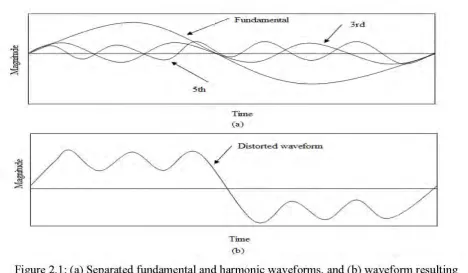
A periodic waveform can be described as a sum of sine waves with the frequency being multiple of the fundamental frequency.
h fundamentalfrequency hf (2.1 )
Where h is an integer.
For example, a fifth harmonic would yield a harmonic component:
5 (50Hz) 250Hzfh in 50Hz Systems (2.2 )
5th
Time (a)
/ Distorted "vaveform
Time (b)
[image:19.595.61.530.61.334.2]5
Figure 2.1: (a) Separated fundamental and harmonic waveforms, and (b) waveform resulting
from summation.
2.1.2 Definition of Total Harmonics Distortion
Harmonics distortion is caused by non-linear devices in the power system. A
non-linear device is one in which the current is not proportional to the source voltage. Harmonic
distortion levels are described by the complete harmonics spectrum with magnitude and
phase angle of each individual harmonic component. Besides, it is also common to use a
single quantity, known as Total Harmonic Distortion (THD), as a measure of effective value
for harmonic distortion (Roger et al., 2002). THD is defined for voltage and current signals,
respectively, as follows:
%THD = x 100 (2.7)
6
This means that the ratio between RMS values of signals, including harmonics and signals; considering only the fundamental frequency, define the THD.
2.2 Harmonic Sources
The harmonics cause disturbances to the utility, such as voltage distortion, power factor correction, capacitor parallel resonance, overheating, overloading power transformer, and communication line interference (Maset et al., 1996). Besides, there are many sources for the harmonics in the power utility. The main sources of harmonics in conventional power systems are summarised below (Nguyen et al., 2000):
• Power Electronic Devices: With the recent advances in power semiconductor technology, more electronics devices, such as phase controllers, inverters, and variable speed drivers, are widely used in the industry. These devices are sensitive to harmonics, and at the same time, they are a source of a high percentage of harmonic currents.
• Electronic Switching Devices: Electronic power processing equipment utilises switching devices. In general, a switching process in electronic devices are synchronized to the AC voltage, but this is unnecessary.
• The voltage-current relationships with non-linear devices: Two examples of such devices are Iron-core reactors and arcing loads. The non-linear V-I curve leads to produce harmonic currents when excited with a periodic input voltage.
• Transformer and saturable reactors: the non-linear magnetizing current of transformers and saturable reactors make them the major harmonic sources from the utility. They have a more pronounce impact during light load.
7
Harmonic standard level, IEEE 519-1992, is the recommended practices and requirements for the harmonics control of electrical power systems. It sets maximum THD limits on voltages and currents that a power system is allowed; therefore, the power conversion system cannot inject harmonics into the grid that causes the system to go above these limits set forth by the standard, and if at all possible; the power conversion system should filter these harmonics.
2.2.1 Effect of Harmonic
The RMS current level is increased due to harmonics, which can lead to an increase in power loss, equipment heating, and voltage sags, as well as the reduction of power factor, communication system interference, error in meter reading, mis-operation of utility relay, and also distortion of power quality (Don et al., 2000; Bhim et al., 1999). The conductors may cause heat as a result of the main effect of harmonics.
The conductors are heated as the current flows in it and this leads to an increase in temperature, due to additional current from the skin effect. Besides conductors, skin effect is also available in transformer due to its eddy current losses.
2.2.2 Harmonic Measurement
Ideally, power supplied by the utility should be a perfect sine wave of standard frequency and magnitude, but power converters add harmonic distortion to the system (Yukihiko et al., 1996). This disturbance has a certain limit for load and utilities. Hence, non-linear load current, I(t), can be represented by the following equation:
1 n nφ
t
nω
sin
I
i(t)
(2.8)8
T0
i
t
dt
T
1
I
(2.9) =
2 n 2 n 2 1I
I
Where, I1 and In are the fundamental and harmonic component respectively, so the
total harmonic current
2 n 2 n harmonicI
I
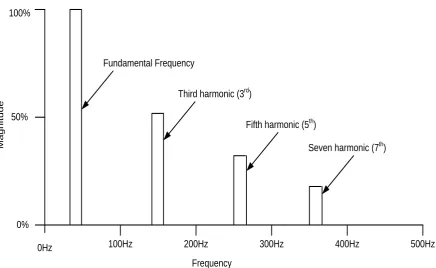
(2.10)2.2.3 Harmonic Spectrum
9
100%
50%
0%
0Hz 100Hz 200Hz 300Hz 400Hz 500Hz
Frequency
Magn
itude
Fundamental Frequency
Third harmonic (3rd)
Fifth harmonic (5th)
[image:23.595.79.516.68.336.2]Seven harmonic (7th)
Figure 2.10: Harmonic spectrum of a sample with distorted wave.
2.3 Theory and basic principles
2.3.1 Advantages of active filter over shunt passive filter
1. When the active filter already in the circuit it not easier to perform both filter just injects the passive filter.
2. Both filters can work independently with several of load characteristic and together it are able to use up in demanding condition where passive filter cannot work excellently due to the parallel resonance problems.
3. Both filter can be used to reduce harmonic over one at a time and perform in power quality
10
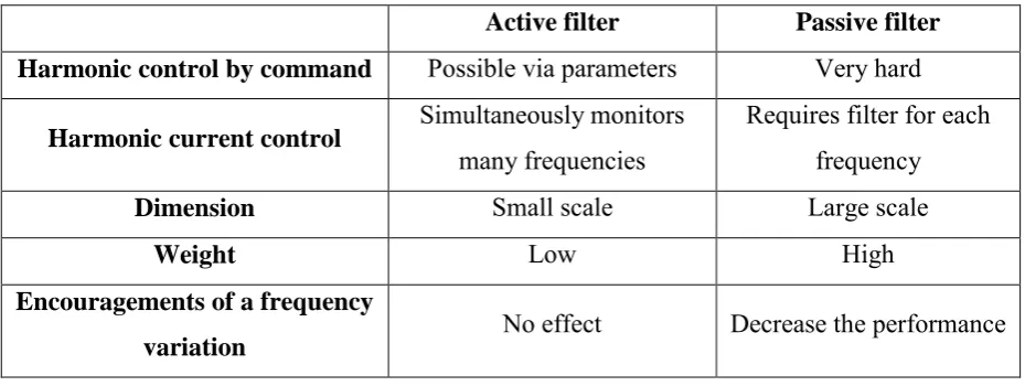
[image:24.595.66.531.142.317.2]2.3.2 Comparison of active filters and shunt passive filter
Table 2.1: Comparison between active filter and passive filter.
Active filter Passive filter Harmonic control by command Possible via parameters Very hard
Harmonic current control Simultaneously monitors many frequencies
Requires filter for each frequency
Dimension Small scale Large scale
Weight Low High
Encouragements of a frequency
variation No effect Decrease the performance
2.4 Review of previous related works
2.4.1 Active power filter
To improve the power quality in harmonic reduction technique is using active filter, by injecting equivalent current or voltage distortion keen on the system, but in diametric value, which spontaneously offsets overcome the genuine distortion appeared on the lap. Active Power filter make use of fast-switching insulated gate bipolar transistors (IGBTs) bridge, which generates an output current of the preferred profile such that every time they are injected into the distribution system or AC lines, it offsets the fundamental load-generated harmonics. The controller part is the most important of the active power filter [3]. The execution and stability of the filter gate will improve when separate control strategies are put into operation to the active power filter. Moreover there are two types of active harmonic filter are designed fpr control scheme.