Flexible Microimplants
for In Vivo Sensing
Thesis by Yu Zhao
In Partial Fulfillment of the Requirements for the Degree of
Doctor of Philosophy
California Institute of Technology Pasadena, California
2014
(Defended August 16th, 2010)
Acknowledgements
To my advisor, Professor Tai: thank you for going through so many difficulties together with me in the past six years. It has not been an easy task. When I stepped onto this path of self-exploration, I hardly understood the academic, emotional and physical difficulties of doing long-term qualitative research over a prolonged period. You have tried every possible way you could think of to push me, lead me, guide me and inspire me. You have helped me to identify my research interest in microimplants. You have guided me to accumulate the building blocks for future research. You have shown me what it takes to become a top researcher. Twenty years ago, you graduated your first PhD student. Twenty years later, I am so honored to become your 42nd PhD student. In another twenty years, I will cordially invite you to celebrate my reaching of new heights.
To Dr. Hsiai (UCLA): You inspired the direction of this research. Your incisive intellect and clear-minded approach helped me at critical moments to think about this project in novel ways. I am extremely grateful for those many emails we exchanged discussing the logic flow of a paper manuscript, the drawing up of a proposal and a potential collaboration we might explore. I have learned from your unique perspective, the importance of logical progression and patterns in science. I am sure my future academic career will benefit a lot from those trainings.
tried to take more responsibilities no matter preparing an experiment, a proposal or a paper manuscript. You have definitely exceeded my best expectation of collaborators. Thank you.
To amazing Mandheerej (Monty) Nandra, thank you for being a mentor and a friend. You are knowledgeable, friendly and helpful. I believe whoever talk to you will instantly love you and never forget you. You are one of the smartest people I know, the one I could always count on for advices and opinions on research-related issues. The little talks about life, the delicious in-n-out burgers, the secrets we shared, the Valentine’s Day we celebrated, they all become my most beautiful memory.
I want to thank Prof. Mark Humayun (USC), Prof. James Weiland (USC), Prof. Wentai Liu (UCLA), Prof. Fangang Zeng (UCI), Dr. Bin Xia (Nurotron Biotechnology), Dr. Yang Fang (Advanced Bionics), Prof. Guoxing Wang (SJTU), Prof. Yao Chen (SJTU), Prof. Eberhart Zrenner (University of Tübingen), Prof. Wilfried Mokwa (University Aachen) for providing insightful discussions about my research projects and my career plan.
tremendous support and trust in the past many years. I have benefited greatly from our many conversations in person and over phone.
I would also like to say thanks to all previous and current group members in Caltech Micromachining Group, Dr. Wen Li, Dr. Siyang Zheng, Dr. Mike Liu, Dr. Quoc (Brandon) Quach, Dr. Ray Huang, Dr. Luca Giacchino, Dr. Jeffrey Lin, Dr. Bo Lu, Dr. Charles DeBoer, Dr. Wendian Shi, Dr. Justin Kim, Dr. Jay Chang, Dr. Jungwook (Jun) Park, Mandheerej (Monty) Nandra, Dongyang (Clark) Kang, Yang Liu, Nick Scianmarello, Xiaoxiao (Shell) Zhang, Aubrey Shapero and Jeff Han, for their assistance, encouragement, and tolerance.
Special thanks go to our lab technician Trevor Roper for his endless maintenance of all kinds of facilities in the group, and our lab administrator Christine Garske for her tremendous help in in managing group’s purchasing orders.
To my friends (too many to list here, but you know who you are): your unconditional trust and support are among the most precious things I have. You always bring out the best in me. The time we shared together has always been something that important for me, as no one can ever buy nor take back.
Abstract
Flexible Microimplants for In Vivo Sensing
Thesis by
Yu Zhao
Doctor of Philosophy in Electrical Engineering California Institute of Technology
The work in this thesis develops two types of microimplants for the application of cardiovascular in vivo biomedical sensing, one for short-term diagnosis and the other for
long-term monitoring.
Despite advances in diagnosis and therapy, atherosclerotic cardiovascular disease remains the leading cause of morbidity and mortality in the Western world. Predicting metabolically active atherosclerotic plaques has remained an unmet clinical need. A stretchable impedance sensor manifested as a pair of quasi-concentric microelectrodes was developed to detect unstable intravascular. By integrating the impedance sensor with a cardiac catheter, high-resolution Electrochemical Impedance Spectroscopy (EIS) measurements can be conducted during cardiac catheterization. An inflatable silicone balloon is added to the sensor to secure a well-controlled contact with the plaque under test in vivo. By deploying the device to the explants of NZW rabbit aorta and live animals,
TABLE OF CONTENTS
LIST OF FIGURES ... X
LIST OF TABLES ... XV
Chapter 1 : Introduction ... 1
1.1 In Vivo Sensing ... 1
1.1.1 Significance of In Vivo Sensing ... 1
1.1.2 Challenges of In Vivo Sensing ... 2
1.1.3 Short-Term In Vivo Sensing ... 3
1.1.4 Long-Term In Vivo Sensing ... 5
1.2 Microimplants for In Vivo Sensing ... 6
1.2.1 Introduction to Microimplants ... 6
1.2.2 Hardware Implementation of Microimplants ... 7
1.2.3 Challenges of Microimplant Development ... 7
1.3 Parylene-based Flexible BioMEMS ... 10
1.3.1 Introduction to BioMEMS ... 10
1.3.2 Introduction to Parylene-based Flexible Technologies ... 11
1.3.3 Introduction to Parylene-Based Flexible Microimplants ... 13
Chapter 2 Stretchable Balloon-Inflatable Impedance Sensor for
Intravascular Plaque Detection ... 26
2.1 Introduction ... 27
2.1.1 Significance of Intravascular Plaque Detection ... 27
2.1.2 Current Technologies for Intravascular Plaque Detection ... 29
2.1.3 Introduction to Electrochemical Impedance Spectroscopy (EIS) ... 30
2.1.4 Feasibility of Applying EIS to Intravascular Plaque Detection ... 31
2.1.5 Challenges of Implementing EIS in Intravascular Plaque Detection ... 32
2.2 Catheter-based Balloon-Inflatable Quasi-Concentric EIS Microelectrode Sensor ... 33
2.2.1 Design ... 33
2.2.2 Fabrication ... 35
2.2.3 Characterization ... 38
2.3 Experiments and Results ... 41
2.3.1 Sample Preparation ... 41
2.3.2 Ex Vivo EIS Measurements in Fat-Fed NZW Rabbits ... 42
2.3.3 In Vivo EIS Measurements in NZW Rabbit ... 44
2.4 Discussion ... 45
Chapter 3 Flexible Microelectrode Membrane for Epicardial ECG
Recording ... 53
3.1 Introduction ... 54
3.1.1 Significance of ECG Recording in Heart Regeneration ... 54
3.1.2 Introduction to ECG Recording System ... 57
3.1.3 Overview of Current ECG Recording Systems ... 59
3.1.4 Challenges of Implementing ECG Recording System in Zebrafish for Heart Regeneration Monitoring ... 60
3.2 Wearable Microelectrode Membrane ... 62
3.2.1 Design ... 62
3.2.2 Fabrication ... 64
3.2.3 Characterization ... 66
3.2.4 ECG Recording from Zebra Fish ... 67
3.2.5 Results and Discussion ... 72
3.2.6 Conclusion ... 76
3.3 Wireless ECG Recording Backpack ... 78
3.3.1 Design ... 79
3.3.2 Implementation and Characterization ... 81
3.3.5 Conclusion ... 90
3.4 Flexible ECG Printed Circuit Membrane ... 90
3.4.1 Design ... 91
3.4.2 Fabrication and Characterization ... 103
3.4.3 Discussion and Conclusion ... 108
3.5 Conclusion ... 109
3.6 References ... 110
Chapter 4 Conclusion ... 113
LIST OF FIGURES
Figure 1.1. An illustration of cardiac catheterization. ... 3
Figure 1.2. Ultra-miniature pressure sensor on catheter tip from Millar’s Mikro-TipR. ... 5
Figure 1.3. Inductive coupling circuit schematic circuit. ... 9
Figure 1.4. Modified stud ball technique used in “MicroFlex”. ... 10
Figure 1.5. Parylene-based high-density microelectrode array. ... 14
Figure 1.6. Parylene-based interconnecting substrate with integrated circuit bare die. ... 15
Figure 1.7. Parylene-based flexible MEMS coil for intraocular power transfer. . 16
Figure 2.1. Development of atherosclerosis by oxLDL filtration. ... 28
Figure 2.2. Comparison of stable and unstable plaques. ... 29
Figure 2.3. Simplified equivalent circuit model for impedance measurement in tissue. ... 31
Figure 2.4. Quasi-concentric microelectrode sensor design. ... 35
Figure 2.5. Fabrication process of the catheter-based balloon-inflatable microelectrode sensor. ... 36
impedance sensor was inserted into the ex-vivo rabbit aorta. (b) Demonstration of balloon
inflation prior to impedance assessment. (c) Demonstration of intravascular balloon inflation. ... 40
Figure 2.8. Characterization of balloon-inflatable impedance sensor in terms of frequency-dependent changes in impedance magnitude and phase. ... 40
Figure 2.9. Ex-vivo EIS acquisition from explanted rabbit aorta and corresponding
histology of the aorta wall. ... 43
Figure 2.10. Deployment of balloon-inflatable EIS sensors via fluoroscopy guidance in NZW rabbits. The position of EIS sensor was visualized in the carotid artery. ... 44
Figure 2.11. In-vivo EIS acquisition in the rabbit carotid arteries. ... 45
Figure 2.12. Equivalent circuit of the in vivo impedance sensing configuration. . 47
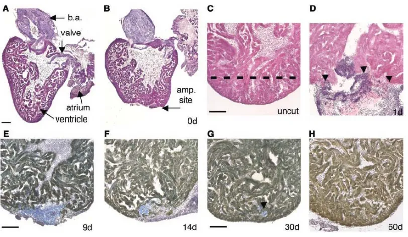
Figure 3.1 Heart regeneration in zebrafish model. ... 55
Figure 3.2. A typical ECG waveform and the characteristics: the P wave, the QRS complex and the T wave. ... 56
Figure 3.3 Hardware implementation of typical ECG Recording Systems ... 59
Figure 3.4 Current ECG recording systems: wired, wearable and implantable. ... 60
Figure 3.5. Device design. ... 63
Figure 3.6. Fabrication process of the microelectrode membrane. ... 65
Figure 3.7. Microelectrode membrane after annealing and assembling. ... 66
through an open-chest incision. The parylene C-based jacket was wrapped around the
zebrafish and placed behind the pectoral fins. ... 68
Figure 3.10. Recording setup inside a faraday cage. ... 69
Figure 3.11. Simplified equivalent recording circuit when recording from electrode A and the ground electrode. ... 70
Figure 3.12 Data processing of recorded ECG signals. ... 71
Figure 3.13. Zebrafish ECG signals acquired via an implanted MEA membrane over 3 days. ... 73
Figure 3.14. ST depression in response to cryo-injury. ... 75
Figure 3.15. Simultaneous four-channel ECG recordings. ... 78
Figure 3.16. Block diagram of the wireless ECG system. ... 81
Figure 3.17. Fabricated device. (a) The manufactured microelectrode membrane with meshed parylene-C pad and meandrous strips. (b) The Scanning Electron Microscope (SEM) photo with four gold microelectrodes and the meshed parylene-C pad. ... 83
Figure 3.18. Circuit schematic of amplification, filtering and data transmission. 84 Figure 3.19. Frequency response of the wireless ECG system ... 84
Figure 3.20. Inductive power transfer with hand-wound primary coil and secondary coil. ... 85
Figure 3.21. Overall power transfer efficiency of inductive coupling link. ... 86
setup of the wireless ECG recording. The neonatal mouse was positioned on the baseplate in enclosed by the transmitting coil. (b) The mouse with device on a baseplate (c) after
insertion into the transmitter coil. ... 88
Figure 3.24. (a) A comparison of ECG signals between the sedated and sedated conditions. Heart rates are ~300 rpm and ~600 rpm for the sedated and non-sedated mice, respectively. (b) A representative signal-processed ECG tracing revealing the P wave, QRS complex and T wave. ... 89
Figure 3.25. Off-the-shelf wirewound unshielded coil for general use in inductive coupling... 92
Figure 3.26. Circuit routing with all the necessary interconnections and pads. ... 93
Figure 3.27. Printed circuit membrane design with debugging routings and tear-off debugging pads highlighted in red. ... 94
Figure 3.28. Schematic diagram of the print circuit membrane with all the components assembled. ... 95
Figure 3.29. Comparison of one-piece circuit and three pieces of sub-circuits. ... 96
Figure 3.30. Design of three-level debugging pads, the connecting pads and the alignment assisting pads. ... 96
Figure 3.31. Cross-sectional view of the bare die assemble. ... 98
Figure 3.32. 3D drawing of the assembled bare die and discrete resistor. ... 98
Figure 3.33. Printed circuit membranes of three sub-circuits. ... 99
Figure 3.34. Three sub-circuits with discrete components assembled. ... 99
debugging pads. ... 100
Figure 3.37. Sub-circuit A+B before and after secondary debugging pads are removed... 101
Figure 3.38. Sub-circuit C with all the discrete components assembled. ... 102
Figure 3.39. Final look of the complete wireless ECG system with sensing electrodes and all the electronic modules. ... 102
Figure 3.40. Microfabrication and assembly flow of the three sub-circuits. ... 103
Figure 3.41. Assembled sub-circuit C and the power transfer efficiency testing. ... 104
Figure 3.42. Sub-circuit A and sub-circuit B connected to debugging printed circuit boards with primary debugging pads. ... 105
Figure 3.43. Sub-circuit A and sub-circuit B connected through bread board for testing. ... 105
Figure 3.44. Assembled sub-circuit A+B. ... 106
Figure 3.45. Testing platform of the wireless ECG recording system prototyped on parylene printed circuit membrane. ... 107
Figure 3.46. Recorded ECG signals from simulator on bench top ... 107
Figure 3.47. Comparison of the ECG wireless recording system prototyped on printed circuit board and on printed circuit membrane. ... 108
LIST OF TABLES
Table 3.1 Signal strength distribution of a representative ECG across each frequency segment. ... 70
Chapter 1
: Introduction
Bian Que was the most recognized physician in ancient China. He was once asked by a King, “The three brothers in your family are all skilled in medicine. Which one of you is the best? Bian Que modestly told the King that his eldest brother was the best, then his second brother, and he was the third. He further explained: My eldest brother gives medical treatment to patients before the onset of a disease. The patients would not even realize they were sick. So it is difficult for them to recognize his medical skills. Only my family members are able to appreciate him. As for my second brother, he treats a disease at its early stage when the symptoms are not very obvious. Thus, people tend to believe he is only capable of treating minor sickness. As for me, I treat a disease when it is already well developed. People are seriously ill. They watch me inject needles, let blood, apply poison drugs on wounds, do surgery…These things help patients by relieving pain and illness and make me well-known all over the country.
The wisdom behind this story is the significance of long-term monitoring, early detection and accurate diagnosis, which can be essentially achieved by in vivo sensing in
the practice of modern medicine.
1.1 In Vivo Sensing
1.1.1 Significance of In Vivo Sensing
In vivo sensing can be referred to specifically as detecting and quantifying
medically useful variables to assess body function [1]. In vivo sensors are developed to
are not able to continuously monitor biological events in situ and often fail to capture the complexity of intact organ systems [2]. Driven by the advancements of both biology and technologies, emerging in vivo sensors have begun to be applied in living systems to
dynamically and continuously monitor biological processes. These in vivo sensors have
great potentials in continuous, rapid monitoring of biological systems in the context of diseases, informing response to therapies, accelerating detection of diseases, and understanding of normal biology [3].
1.1.2 Challenges of In Vivo Sensing
The challenges of in vivo sensing lie in both the inaccessibility of in vivo tissues
and fundamental difficulties in sensor design and application [2]. Normally, an in vivo
sensor is simply composed of a detector (such as an electrode, antibody, aptamer, peptide or enzyme) paired with a detection method (which may be electrochemical, optical or magnetic, among others) [4-7]. Accordingly, sensing in vivo requires both the detector
and detection method biocompatible, nontoxic, not perturbing the system being examined, capable of monitoring signals within a living system with necessary sensitivity and specificity [1, 3, 4].
The time scale of in vivo sensing could vary from hours or days to years, thus
imposing different challenges and constraints on the hardware implementation [8, 9]. In this dissertation, in vivo sensing is generally classified into short-term invivo sensing and
long-term in vivo sensing. In both scenarios, minimal perturbation of normal biology is of
utmost importance while developing in vivo sensors [2]. This includes minimizing the
1.1.3 Short-Term In Vivo Sensing
Short-term in vivo sensing commonly aims to accurately diagnose a disease in its
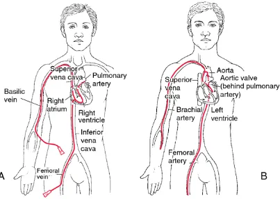
[image:21.595.108.511.241.527.2]early stage. It has been found to integrate well with available minimally invasive diagnosis and treatment such as cardiac catheterization [10].
Cardiac catheterization enables doctors to access diseased sites that need to be monitored and treated via the circulatory system [11]. Specialized tubes or catheters are threaded up through the blood vessels in the groin, arm, or neck to an area of the body that needs diagnosis and treatment (Fig. 1.1). The problem is then checked from the inside of the blood vessel. Depending on the blood vessel sizes, the catheters are approximately 0.3-3.0 mm in diameter and 1.5 m in length [11]. The merits of this approach include that catheterization does not require surgical incisions at the monitoring site, hospital stays are usually one night or less, and the discomfort and recovery times afterward are minimal. Therefore, cardiac catheterization is considered a minimally-invasive procedure.
During cardiac catheterization, short-term in vivo sensing can gather additional
information for diagnosis, monitoring during operation and checking results after procedures [10].
Figure 1.2. Ultra-miniature pressure sensor on catheter tip from Millar’s Mikro-TipR.
1.1.4 Long-Term In Vivo Sensing
Long-term in vivo sensing can be a key component of an ideal monitoring system
for early detection or a close-loop treatment for uncured disease. Two examples are discussed here.
glaucoma, but the visual loss can be slowed or eliminated with early diagnosis and proper treatment to lower the high intraocular pressure. Thus, long-term implantable sensors that can continuously monitor intraocular pressure have been widely developed for an early detection and treatment [17, 18].
The second example is the implantable glucose sensor. Currently, the finger-prick sampling method of glucose monitoring is predominantly used in diabetes management. Nevertheless, there has always been a strong push for continuous glucose monitoring, which could form a close-loop control system and make real-time and optimal insulin delivery [19]. With a well-regulated blood glucose level, the short-term crises and long-term complications associated with diabetes could be minimized [9, 19]. A wide range of in-vivo glucose electrochemical sensors, presenting different needle designs, materials and membrane coatings, has been studied in both industry and research [20-22].
1.2 Microimplants for In Vivo Sensing
1.2.1 Introduction to Microimplants
The scale of microimplants in this dissertation has two folds. First, devices that are intended to function inside the body for some period (short-term or long-term) and secondly, devices that have at least one part made using integrated circuit-like fabrication technology with micron-sized features.
devices [25] and the embedded monitoring devices targeting a variety of physiological variables including oxygen, glucose, pH level, pressure, and temperature [9, 26, 27].
1.2.2 Hardware Implementation of Microimplants
For the application of in vivo sensing, the hardware implementation of
microimplants usually shares a common set of four function modules including signal sensing, signal processing, data transmission and power transmission [1, 11]. Physiological signals are obtained by front-end sensors, processed and transmitted through a wired or wireless communication scheme to the exterior monitoring/diagnosing unit. Signals need to be transmitted through every medium in between the implant and the external unit. A wireless data transmission could be achieved by modulating different energy forms, such as electromagnetic waves, light and ultrasound [28, 29]. Power can be provided by wired connection, implantable battery, wireless energy transmission or energy harvesting.
1.2.3 Challenges of Microimplant Development
The requirements of microimplants are application specific, but there are several challenges commonly encountered in module implementation. Three of the major challenges as well as the previous research efforts conducted to tackle the challenges are reviewed in this section.
1.2.3.1 Sensor
implantation. The front-end signal-sensing module forms the interface between the biological tissue and the engineering device. Careful consideration is given to the mechanical properties of the biological tissue, the anatomical structure of the implantation site, the relative mechanical movement between the implant and the surrounding tissue, when selecting implant materials and determining the mechanical design of the implant. For one example, the chemical composition of the implant should not increase or extend the presence of the implant [30]. For another example, sharp edges and corners should be avoided [31]. Furthermore, biocompatible coatings could be important to further minimize the body’s immune response. Meanwhile, the surgical procedure performed to implant a device may also cause a series of foreign body reactions. Therefore, the device should have an optimal design to minimize surgical damage during implantation [32].
1.2.3.2 Power
For short-term in vivo sensing, it is practical to make wired connections to supply
power to the sensor. For long-term in vivo sensing, wired powering connections can
restrict the movement and increase the chances of infection. Using an implantable battery is an option, but the increased total size of the device limits the choice of implantation sites. Also, battery lifetime is usually limited, and even rechargeable batteries have a limited number of recharging cycles. Energy harvesting could be used in implants, but the amount of power collected from the body is usually too low for practical use.
The medium between the coils could include air, water, and biological tissue (Fig. 1.3). To obtain a higher power coupling efficiency, an external capacitor is added to form a tuned-in-series external resonator and a turned-in-parallel implanted resonator with the pair of coils, respectively. When the transmitter coil is driven by the sinusoidal signals at the resonating frequency, it creates a changing electromagnetic field. The implanted coil captures a portion of it and has current produced in the resonator. Considering the tissue absorption rate and power transfer efficiency, the operational frequency, which is the resonating frequency at the same time, should be in the range of 1 and 20 MHz and the power transmitted from the external unit should not exceed 10 mW/cm2 in compliance with government safety standards.
Figure 1.3. Inductive coupling circuit schematic circuit.
1.2.3.3 Integration
Application-specific integrated circuits (ASICs) can achieve high integration density of the electronic circuitry including single transmission, power management as well as signal processing. However, the major challenge lies in the hybrid integration of the whole system and how to further minimize it [33]. On the other hand, a flexible substrate is preferred considering the implantable systems could be in direct contact with delicate and soft tissue and biological structures.
For small volume production at the proof of concept stage, flip-chip bonding and a modified stud ball technique (“MicroFlex Technique”) have been developed for integration of standard integrated circuits (ICs) and discrete components onto the flexible interconnecting polyimide substrate [34] (Fig. 1.4).
Figure 1.4. Modified stud ball technique used in “MicroFlex”.
1.3 Parylene-based Flexible BioMEMS
1.3.1 Introduction to BioMEMS
from the microfabrication processes used for integrated circuit fabrication and semiconductor manufacturing, then were later adapted and extended to include some other similar techniques. The major concepts and principles behind MEMS technologies are photolithography, thin films deposition and etching techniques. By repeating the sequences of deposition, photolithography patterning and etching, desired features can be produced in a layer-by-layer fashion.
BioMEMS is a sub-domain of MEMS and its emergency has given rise to a lot of interdisciplinary research in biomedical applications. A lot of bioMEMS devices for in vitro diagnostic use have been fabricated and tested in the laboratory stage, such as micro
channels, micro valves, micro cantilevers, micro pumps and micro reservoirs [35-37]. There has long been interest in applying bioMEMS technologies for in vivo sensing
because bioMEMS technologies offer great potential in making devices and components with small and well-controlled features, high reproducibility and uniformity, low weight and cost, superior functionality and performance [38]. In addition, in recent years, bioengineering technology and molecular technology have been combined with bioMEMS technology. Some biocompatible materials have been introduced and widely used in bioMEMS fabrication. Therefore, bioMEMS technologies have provided unique opportunities to make big impacts in the biomedical, surgical and pharmaceutical fields.
1.3.2 Introduction to Parylene-based Flexible Technologies
benzene ring), parylene C (one chlorine on the benzene ring), and parylene D (with two chlorines on the benzene ring) (Fig. 5).
The advantages of using parylene, and more specially, parylene C for in vivo
applications include high elongation (up to 200%), low Young’s modulus (around 2.8-4 GPa), FDA approval for chronic human implant (USP class VI), conformal pinhole-free vapor deposition, ease of etching in oxygen plasmas, high resistivity, and low permeability against water, gasses and ions [39, 40].
1.3.2.1 Parylene Deposition
Parylene layers are deposited in a vapor deposition polymerization process [40]. As the starting substance, the dimer of a specific parylene type is heated up until it vaporizes and later on splits into a monomeric gas. When the gas reaches the deposition chamber, it cools down to room temperature and polymerizes on the target. The deposition process allows a conformal coating of the target from tall sides and even sharp edges. Typical layer thicknesses range from sub micrometers to tens of micrometers.
1.3.2.2 Parylene Dry Etching
1.3.2.3 Parylene Adhesion
It is generally believed that parylene deposited on a hydrophobic surface shows good adhesion, and deposition on a hydrophilic surface leads to poor adhesion [42]. Poor adhesion is undesirable during device fabrication, because the parylene interface can be easily delaminated via chemical attack. For example delamination may occur due to hydrolysis if the device is placed in an aqueous environment. One exception is in a process step where the parylene membrane needs to be peeled off from the substrate. Here, the poor adhesion is clearly favored.
Parylene shows poor adhesion on oxidized silicon surfaces due to its surface hydrophilicity. Hexamethyldisiloxane (HMDS) is the most frequently used chemical to reduce the to-silicon adhesion. This technique is applied when making parylene-based devices that need to be peeled off from the carrier wafer.
There are several methods that can enhance the adhesion between parylene and silicon. Some chemicals, such as A-174 provided by Specialty Coating Systems (SCS), are aimed at enhancing the adhesion by chemical methods. It was also that found parylene shows better adhesion on rougher surfaces. Surface roughness and the anchoring designs both contribute to the enhanced adhesion.
1.3.3 Introduction to Parylene-Based Flexible Microimplants
telemetry-recovery and driving ASIC and a flexible interconnecting substrate for integrating all the modules [44].
1.3.3.1 Parylene–Based Flexible Microelectrode Array
Flexible parylene-based microelectrode arrays have been microfabricated with thin-film platinum on parylene substrate (Fig. 1.5). A single-metal-layer process or a dual-metal-layer process could be used to meet the needs of extremely high-density stimulation applications. Some electrodes can survive for more than 430 million pulses without failing. A chronic implantation study of the mechanical effects of parylene-based microelectrode arrays on the retina over a six month follow-up period has shown excellent stability [45].
Figure 1.5. Parylene-based high-density microelectrode array.
1.3.3.2 Parylene-Based Flexible Assembly
1.6). The substrate has a pocket designed for the ASIC to sit inside. High-lead electrical connections have been made by conductive epoxy through a high-yield “squeeze” technique.
Figure 1.6. Parylene-based interconnecting substrate with integrated circuit bare die.
1.3.3.3 Parylene-Based Flexible Power Coil
parylene-metal-parylene skin technology. The fold-and-bond technology has been demonstrated to be an effective technique to obtain a high-Q coil. The coil has proven to be mechanically flexible with good electrical performance [47].
Figure 1.7. Parylene-based flexible MEMS coil for intraocular power transfer.
1.4 Goal and Layout of the Dissertation
The work of this thesis is to develop flexible microimplants for clinical and biological needs in in vivo sensing. In Chapter 1, the needs of in vivo sensing are
classified into two types, long-term and short-term. Then, design strategies of microimplants for in vivo sensing in terms of hardware implementation are discussed.
The hardware function modules and challenges of building these modules are identified and explored in the following chapters.
Chapter 2 reports a stretchable impedance sensor manifested as a pair of quasi-concentric microelectrodes that can be integrated with a cardiac catheter to detect unstable intravascular plaque during cardiac catheterization. It is intended to perform short-term in vivo sensing and ideally achieve high-accuracy diagnosis. An inflatable
silicone balloon is added to the sensor to secure a well-controlled contact with the plaque
aorta for detection of lipid-rich atherosclerotic plaques, and to live animals for demonstration of balloon inflation and electrochemical impedance spectroscopy (EIS) measurements. This chapter formed the bulk of the publication in Biosensors and Bioelectronics [48].
Chapter 3 develops a flexible sensor membrane for multi-site epicardial ECG monitoring of heart regeneration in zebrafish. To meet the requirements of long-term in vivo sensing, the sensor membrane went through a series of design optimizations to
enable long-term biocompatibility and reliable functionality. To further achieve continuous monitoring, the wireless operation of the sensor membrane was demonstrated by prototyping signal processing, wireless data transmission and wireless power management modules on a printed circuit board (PCB). The device was tested on neonatal mouse instead of zebrafish because of size and weight limitations. To further reduce the size and weight, a parylene-based printed circuit membrane was designed and fabricated to replace the PCB. The flexible, light-weight and compact parylene printed circuit membrane was monolithically fabricated with sensor electrodes and provided mechanical substrate and electrical interconnection for electronic components. The miniaturized wireless ECG recording implant can be potentially deployed on small animal models and achieve minimally invasive needle injection. The work provided the material for a conference proceeding [49] and two journal papers [50] [51]
Chapter 4 recapitulates the key outcomes of this body of work and how they contribute to the field of in vivo biomedical sensing and its hardware implementation.
1.5 References
[1] G. S. Wilson and R. Gifford, "Biosensors for real-time in vivo measurements,"
Biosensors and Bioelectronics, vol. 20, pp. 2388-2403, 6/15/ 2005.
[2] M. A. Eckert, P. Q. Vu, K. X. Zhang, D. K. Kang, M. M. Ali, C. J. Xu, et al.,
"Novel Molecular and Nanosensors for In Vivo Sensing," Theranostics, vol. 3, pp.
583-594, 2013.
[3] M. A. Eckert and W. Zhao, "Opening windows on new biology and disease mechanisms: development of real-time in vivo sensors," Interface Focus, vol. 3,
June 6, 2013 2013.
[4] A. Ramesh, F. Ren, P. R. Berger, P. Casal, A. Theiss, S. Gupta, et al., "Towards
in vivo biosensors for low-cost protein sensing," Electronics Letters, vol. 49, pp.
450-451, Mar 2013.
[5] M. L. James and S. S. Gambhir, "A MOLECULAR IMAGING PRIMER: MODALITIES, IMAGING AGENTS, AND APPLICATIONS," Physiological Reviews, vol. 92, pp. 897-965, Apr 2012.
[6] K. W. Plaxco and H. T. Soh, "Switch-based biosensors: a new approach towards real-time, in vivo molecular detection," Trends in Biotechnology, vol. 29, pp. 1-5,
Jan 2011.
[7] N. J. Ronkainen, H. B. Halsall, and W. R. Heineman, "Electrochemical biosensors," Chemical Society Reviews, vol. 39, pp. 1747-1763, 2010.
phase based on sensing film coating optoelectronic elements," Sensors and Actuators B-Chemical, vol. 144, pp. 232-238, Jan 2010.
[9] S. V. Edelman, D. J. Beatty, M. Bouvet, J. C. Fisher, and W. T. Cefalu,
"Continuous glucose sensing with a long-term subcutaneous implant in patients with Type 1 diabetes," Diabetologia, vol. 45, pp. A27-A27, Aug 2002.
[10] C. Tei, R. A. Nishimura, J. B. Seward, and A. J. Tajik, "Noninvasive Doppler-derived myocardial performance index: Correlation with simultaneous
measurements of cardiac catheterization measurements," Journal of the American Society of Echocardiography, vol. 10, pp. 169-178, Mar 1997.
[11] Y. Haga and M. Esashi, "Biomedical microsystems for minimally invasive diagnosis and treatment," Proceedings of the Ieee, vol. 92, pp. 98-114, Jan 2004.
[12] J. F. L. Goosen, P. J. French, and P. M. Sarro, "Pressure and flow sensor for use in catheters," in Micromachined Devices and Components V. vol. 3876, P. J.
French and E. Peeters, Eds., ed Bellingham: Spie-Int Soc Optical Engineering, 1999, pp. 38-45.
[13] C. Y. Li, P. M. Wu, J. A. Hartings, Z. Z. Wu, C. H. Ahn, D. LeDoux, et al.,
"Smart catheter flow sensor for real-time continuous regional cerebral blood flow monitoring," Applied Physics Letters, vol. 99, p. 4, Dec 2011.
[14] K. Tsukada, S. Sakai, K. Hase, and H. Minamitani, "Development of catheter-type optical oxygen sensor and applications to bioinstrumentation," Biosensors & Bioelectronics, vol. 18, pp. 1439-1445, Oct 2003.
[15] C. Y. Li, P. M. Wu, Z. Z. Wu, C. H. Ahn, D. LeDoux, L. A. Shutter, et al., "Brain
catheter temperature sensors," Biomedical Microdevices, vol. 14, pp. 109-118,
Feb 2012.
[16] K. Gungor, P. J. Hotez, V. Ozdemir, and S. Aynacioglu, "Glaucomics: A Call for Systems Diagnostics for 21(st) Century Ophthalmology and Personalized Visual Health," Omics : a journal of integrative biology, vol. 18, pp. 275-9, 2014 May
(Epub 2014 Apr 2014.
[17] N. Xue, S. P. Chang, and J. B. Lee, "A SU-8-Based Microfabricated Implantable Inductively Coupled Passive RF Wireless Intraocular Pressure Sensor," Journal of Microelectromechanical Systems, vol. 21, pp. 1338-1346, Dec 2012.
[18] F. Piffaretti, D. Barrettino, P. Orsatti, L. Leoni, and P. Stegmaier, "Rollable and implantable intraocular pressure sensor for the continuous adaptive management of glaucoma," Conference proceedings : ... Annual International Conference of the IEEE Engineering in Medicine and Biology Society. IEEE Engineering in Medicine and Biology Society. Conference, vol. 2013, pp. 3198-201, 2013 2013.
[19] D. C. Klonoff, "Continuous glucose monitoring - Roadmap for 21st century diabetes therapy," Diabetes Care, vol. 28, pp. 1231-1239, May 2005.
[20] S. Q. Gu, Y. L. Lu, Y. P. Ding, L. Li, H. S. Song, J. H. Wang, et al., "A
droplet-based microfluidic electrochemical sensor using platinum-black microelectrode and its application in high sensitive glucose sensing," Biosensors &
Bioelectronics, vol. 55, pp. 106-112, May 2014.
[21] Y. Yoon, G. S. Lee, K. Yoo, and J. B. Lee, "Fabrication of a Microneedle/CNT Hierarchical Micro/Nano Surface Electrochemical Sensor and Its In-Vitro
[22] A. Heller and B. Feldman, "Electrochemical glucose sensors and their applications in diabetes management," Chemical Reviews, vol. 108, pp.
2482-2505, Jul 2008.
[23] D. Difrancesco, "PACEMAKER MECHANISMS IN CARDIAC TISSUE,"
Annual Review of Physiology, vol. 55, pp. 455-472, 1993.
[24] M. Mirowski, "THE AUTOMATIC IMPLANTABLE CARDIOVERTER-DEFIBRILLATOR - AN OVERVIEW," Journal of the American College of Cardiology, vol. 6, pp. 461-466, 1985.
[25] M. S. Humayun, J. D. Weiland, G. Y. Fujii, R. Greenberg, R. Williamson, J. Little, et al., "Visual perception in a blind subject with a chronic microelectronic retinal
prosthesis," Vision Research, vol. 43, pp. 2573-2581, Nov 2003.
[26] G. Koley, J. Liu, M. W. Nomani, M. B. Yim, X. J. Wen, and T. Y. Hsia, "Miniaturized implantable pressure and oxygen sensors based on
polydimethylsiloxane thin films," Materials Science & Engineering C-Biomimetic and Supramolecular Systems, vol. 29, pp. 685-690, Apr 2009.
[27] A. Khairi, C. Y. Wu, Y. Rabin, G. Fedder, J. Paramesh, D. Schwartzman, et al.,
"Ultra-Low Power Frequency and Duty-cycle Modulated Implantable Pressure-Temperature Sensor," in 2013 Ieee Biomedical Circuits and Systems Conference,
ed New York: Ieee, 2013, pp. 226-229.
[29] A. Kiourti and K. S. Nikita, "A Review of Implantable Patch Antennas for Biomedical Telemetry: Challenges and Solutions [Wireless Corner]," Antennas and Propagation Magazine, IEEE, vol. 54, pp. 210-228, 2012.
[30] U. Dapunt, T. Giese, F. Lasitschka, J. Reinders, B. Lehner, J. P. Kretzer, et al.,
"On the inflammatory response in metal-on-metal implants," Journal of translational medicine, vol. 12, p. 74, 2014 2014.
[31] S. Barkam, S. Saraf, and S. Seal, "Fabricated Micro-Nano Devices for In vivo and In vitro Biomedical Applications," Wiley Interdisciplinary Reviews-Nanomedicine and Nanobiotechnology, vol. 5, pp. 544-568, Nov 2013.
[32] M. W. Ashraf, S. Tayyaba, and N. Afzulpurkar, "Micro Electromechanical Systems (MEMS) Based Microfluidic Devices for Biomedical Applications,"
International Journal of Molecular Sciences, vol. 12, pp. 3648-3704, Jun 2011.
[33] W. Mokwa, "Medical implants based on microsystems," Measurement Science & Technology, vol. 18, pp. R47-R57, May 2007.
[34] T. Stieglitz, H. Beutel, and J. U. Meyer, ""Microflex" - A new assembling technique for interconnects," Journal of Intelligent Material Systems and Structures, vol. 11, pp. 417-425, Jun 2000.
[35] E. Nuxoll, "BioMEMS in drug delivery," Advanced Drug Delivery Reviews, vol.
65, pp. 1611-1625, Nov 2013.
[37] A. C. R. Grayson, R. S. Shawgo, A. M. Johnson, N. T. Flynn, Y. W. Li, M. J. Cima, et al., "A BioMEMS review: MEMS technology for physiologically
integrated devices," Proceedings of the Ieee, vol. 92, pp. 6-21, Jan 2004.
[38] T. James, M. S. Mannoor, and D. V. Ivanov, "BioMEMS - Advancing the frontiers of medicine," Sensors, vol. 8, pp. 6077-6107, Sep 2008.
[39] J. Noordegraaf, "Conformal coating using parylene polymers," Medical device technology, vol. 8, pp. 14-20, 1997 1997.
[40] G. E. Loeb, M. J. Bak, M. Salcman, and E. M. Schmidt, "PARYLENE AS A CHRONICALLY STABLE, REPRODUCIBLE MICROELECTRODE
INSULATOR," Ieee Transactions on Biomedical Engineering, vol. 24, pp.
121-128, 1977.
[41] C. P. Tan and H. G. Craighead, "Surface Engineering and Patterning Using Parylene for Biological Applications," Materials, vol. 3, pp. 1803-1832, Mar
2010.
[42] J. M. Hsu, L. Rieth, S. Kammer, M. Orthner, and F. Solzbacher, "Effect of thermal and deposition processes on surface morphology, crystallinity, and adhesion of Parylene-C," Sensors and Materials, vol. 20, pp. 87-102, 2008.
[43] W. Li, D. C. Rodger, E. Meng, J. D. Weiland, M. S. Humayun, and Y. C. Tai, "Wafer-Level Parylene Packaging With Integrated RF Electronics for Wireless Retinal Prostheses," Journal of Microelectromechanical Systems, vol. 19, pp.
[44] D. C. Rodger, A. J. Fong, W. Li, H. Ameri, I. Lavrov, H. Zhong, et al., High-density flexible parylene-based multielectrode arrays for retinal and spinal cord stimulation. New York: Ieee, 2007.
[45] D. C. Rodger, A. J. Fong, W. Li, H. Ameri, A. K. Ahuja, C. Gutierrez, et al.,
"Flexible parylene-based multielectrode array technology for high-density neural stimulation and recording," Sensors and Actuators B: Chemical, vol. 132, pp.
449-460, 6/16/ 2008.
[46] J. H. Chang, R. Huang, and T. Yu-Chong, "High density 256-channel chip integration with flexible parylene pocket," in Solid-State Sensors, Actuators and Microsystems Conference (TRANSDUCERS), 2011 16th International, 2011, pp.
378-381.
[47] C. Po-Jui, K. Wen-Cheng, L. Wen, Y. Yao-Joe, and T. Yu-Chong, "Q-enhanced fold-and-bond MEMS inductors," in Nano/Micro Engineered and Molecular Systems, 2008. NEMS 2008. 3rd IEEE International Conference on, 2008, pp.
869-872.
[48] H. Cao, F. Yu, Y. Zhao, N. Scianmarello, J. Lee, W. D. Dai, et al., "Stretchable
electrochemical impedance sensors for intravascular detection of lipid-rich lesions in New Zealand White rabbits," Biosensors & Bioelectronics, vol. 54, pp.
610-616, Apr 2014.
[49] Z. Yu, Y. Fei, C. Hung, C. Honglong, Z. Xiaoxiao, T. K. Hsiai, et al., "A
wearable percutaneous implant for long term zebrafish epicardial ECG
& EUROSENSORS XXVII), 2013 Transducers & Eurosensors XXVII: The 17th International Conference on, 2013, pp. 756-759.
[50] F. Yu, Y. Zhao, J. Gu, K. Quigley, N. Chi, Y.-C. Tai, et al., "Flexible
microelectrode arrays to interface epicardial electrical signals with intracardial calcium transients in zebrafish hearts," Biomedical Microdevices, vol. 14, pp.
357-366, 2012/04/01 2012.
[51] H. Cao, Y. Zhao, F. Yu, X. Zhang, J. Tai, J. Lee, et al., "Wearable Multi-Channel
Chapter 2
Stretchable Balloon-Inflatable
Impedance Sensor for Intravascular
Plaque Detection
This chapter develops a balloon-inflatable impedance sensor for intravascular plaque detection during cardiac catheterization. The significance of this clinical need for diagnosis is described first. After introducing the sensing strategy of electrochemical impedance spectroscopy (EIS), the feasibility and challenges of implementing this strategy to intravascular plaque detection are discussed respectively (Section 2.1). A novel catheter-based EIS sensor manifested as a pair of quasi-concentric microelectrodes was designed, fabricated and characterized (Section 2.2). An inflatable balloon design was additionally added to the sensor for a better in vivo contact. In the experiment section
(Section 2.3), the procedures of sample preparation, ex vivo measurement and in vivo
measurement are presented in detail and the experimental results showed the capability of the sensor to distinguish impedance magnitude and phase differences between different types of plaques. Finally, Section 2.4 summarizes the work and compares with other state-of-the-art technologies.
As one type of short-term in vivo sensing, the impedance sensor was initially
designed with a cardiac catheterization to be minimally invasive. The sensor features a novel quasi-concentric microelectrode design which achieved an accurate diagnosis of early-stage unstable plaque. Moreover, the inflatable balloon facilitated a well-controlled
top of that, the sensor has also presented adequate expandability and stretchability to accommodate balloon inflation.
2.1 Introduction
2.1.1 Significance of Intravascular Plaque Detection
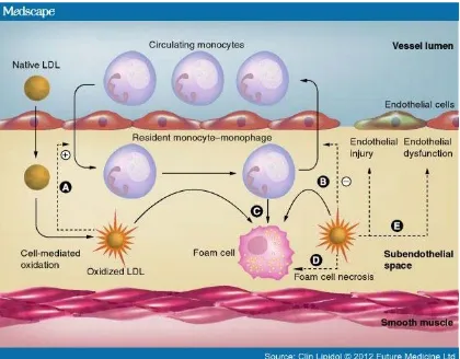
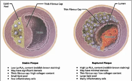
Atherosclerosis (also known as arteriosclerotic vascular disease or ASVD) refers to the thickening of an artery wall as a result of invasion and accumulation of fatty materials [1]. Its development starts with the low-density lipoprotein molecules present in the blood stream which get oxidized by free radicals. Once oxidized, LDL (oxLDL) molecules in contact with artery endothelium can cause damage to endothelial cells and result in increased permeability of the endothelium. Then oxLDL molecules can easily migrate into the artery wall. As a result of the damage caused to the blood vessel, an inflammatory response is triggered. White blood cells enter the artery wall to ingest oxLDL but are not able to process it, and instead they will turn into large foam cells with high lipid content. Foam cells die and rupture, further propagating the inflammatory response. Eventually, fatty substances, cholesterol, waste products, calcium and other substances build up and form a plaque [2]. Fibrous tissue can form a hard cover over the affected area known as the fibrous cap (Fig. 2.1).
heart attack and stroke which are caused by artery thrombosis to the heart and brain respectively [2].
Figure 2.1. Development of atherosclerosis by oxLDL filtration.
the same time, the macrophages within the plaque can release enzymes that break down collagen in the cap, thus the cap gets weaker and more prone to rupture. Therefore, the detection of unstable plaques is of utmost importance and holds the potential to identify patients for selective intervention.
Figure 2.2. Comparison of stable and unstable plaques.
2.1.2 Current Technologies for Intravascular Plaque Detection
near-infrared light to visualize vascular microstructures and it has been successfully applied for the characterization of coronary atherosclerotic plaques in vivo [5].
Intravascular magnetic resonance spectroscopy (IVMR) is a new technique developed to identify specifically the lipid component of plaques based on the self-diffusion of water molecules that is translated into a lipid fraction index (LFI) [6]. These four imaging modalities have in common the ability to give a detailed assessment of the composition of atherosclerotic plaques but do differ in the means of achieving this.
2.1.3 Introduction to Electrochemical Impedance Spectroscopy (EIS)
The impedance Z of a system actually measures the dielectric properties of a medium as a function of frequency [7]. The impedance depends on the interaction between the medium electric dipole and externally applied field. Therefore, it can be determined by applying a sinusoidal voltage perturbation with a small amplitude and detecting the current response. Based on this definition, it can be calculated as:
Z
∅ ,
where V(t) is a voltage-time function and I(t) is the responding current-time function, and are maximum voltage and current signals, f is the frequency, t is the time, and ∅ is the phase shift.
The impedance is measured at different frequencies, so called “spectroscopy”. The electrochemical impedance spectroscopy (EIS) is widely used to analyze the complex electrical resistance of a system. It can respond to surface phenomena and bulk properties. For example, as a biosensor, it can detect the binding events on the transducer surface. With the development of instrumentation, EIS has found more applications in characterizing surfaces, layers, membranes, and exchange and diffuse processes in recent years [8].
In order to characterize biological tissue, metallic electrodes must be introduced into the system. By applying a sinusoidal stimulating voltage, the current flows through all the components of a system, including the working electrode, the biological tissue and the counter electrodes. The measured impedance is contributed to by all the individual impedances.
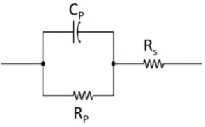
[image:49.595.251.398.500.591.2]Various equivalent circuit models have been proposed to interpret the impedance spectrum. A simple yet efficient model for the electrochemical impedance in tissue is represented as a parallel capacitance, CP, shunted by a charge transfer resistance RP, in series with the tissue resistance RS (Fig. 2.3).
Figure 2.3. Simplified equivalent circuit model for impedance measurement in tissue.
2.1.4 Feasibility of Applying EIS to Intravascular Plaque Detection
pro-inflammatory substrates; namely, oxLDL and macrophage-derived foam cells which infiltrate and engender distinct electrochemical properties [9]. Hence, it is feasible to determine the plaques’ frequency-dependent electrical and dielectrical behavior by recording the electric impedance of a tissue over a frequency range. Since the electrical properties of biological tissues are related to their physiological and morphological properties, EIS is suitable for the detection of tissue composition and could potentially identify plaques that are prone to rupture.
2.1.5 Challenges of Implementing EIS in Intravascular Plaque Detection
There are several challenges to the implementation of EIS for intravascular plaque detection.
First, for in vitro sensing applications, a large surface area provided by the inert
platinum or carbon electrode is commonly used as the counter electrode, providing both high charge transfer resistance and double-layer capacitance. The overall impedance contributed by counter electrode is considered negligible. For intravascular EIS applications, where a high spatial resolution is necessary, the confined space in the catheters warrants close packaging of both the counter and working electrodes. For this reason, EIS measurements must account for the electrochemical interference at both the counter and working electrode interfaces.
Secondly, because of the non-homogeneous tissue composition and uneven endoluminal topography, the current distribution generated from applying voltage to the impedance electrodes will be uneven. This is different from ex vivo impedance
design and an improved arrangement of the working electrode and counter electrode are needed.
Thirdly, a stable and proper contact of the electrodes with the plaque under test is very important to enhance the qualities of the recorded signal. An external force that can push the electrodes towards the plaque and keep the electrodes in contact is ideal. Considering the plaques tendency to rupture, the applied force needs to be small and gentle. An additional sensor feature was considered here to provide this well-controlled pushing force in vivo.
2.2 Catheter-based Balloon-Inflatable Quasi-Concentric EIS
Microelectrode Sensor
2.2.1 Design
To facilitate the detection and diagnosis of the non-obstructive and pro-inflammatory atherosclerotic plaque, a pair of quasi-concentric microelectrodes, integrated onto an inflatable silicone balloon, was designed to adhere to a catheter tip to perform the EIS in vivo sensing during catheterization.
increase the yield. More importantly, the central and outer microelectrodes, i.e., the working and counter electrodes, are fabricated monolithically and have exactly same surface properties.
The quasi-concentric microelectrodes are connected to the contact pads through sinusoidal lines for an improved expandability and stretchability during balloon inflation. The contact pads establish electrical connections with the external energy source through medical-grade coaxial wire, and supply the excitation voltage across the central and outer microelectrodes.
There are four major advantages to this design: (1) The quasi-concentric configuration can provide constant and symmetric displacement currents between working and counter electrodes. (2) The quasi-concentric electrodes may allow for EIS measurement independent of the surrounding solutions or blood and the orientation of the tissues. (3) The fabrication process and post connecting process for making the quasi-concentric electrodes are simple and reliable. (4) The small dimensions of the microelectrodes can achieve a higher spatial resolution in the regions of pro-inflammatory states. (5) The small separation between the working and counter electrodes make the measured impedance mainly sensitive to tissue in close proximity and independent of the lumen diameters, blood volumes and flow rates when the in vivo
contact is made.
An inflatable silicone balloon is designed to inflate in vivo and push the electrodes
the anchor pads permeates the through holes and bonds together with the silicone balloon body. Because the balloon mainly expands in the radial direction, the sinusoidal cables mostly extend in the longitudinal direction.
Figure 2.4. Quasi-concentric microelectrode sensor design.
2.2.2 Fabrication
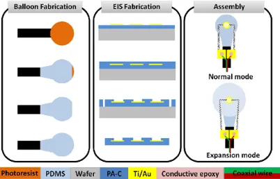
The fabrication process required four main steps: (1) Fabrication of the silicone balloon. (2) Assembly of the sealed tubing connecting the balloon to a syringe. (3) Microfabrication of the impedance sensor. (4) Securing the impedance sensor to the balloon (Fig. 2.5).
thoroughly mixed in a 1:1 ratio of part A and part B, and then painted onto the surface of PR and the capillary tubing. An opening was intentionally created for the subsequent PR release. Ensuring an even coverage of the balloon is important for symmetrical inflation. The modulus of elasticity increased with increased curing duration and temperature. Afterwards, it was fully submerged into a beaker of acetone to dissolve the PR, thereby forming the cavity and allowing for the removal of the inner steel tube. The hole on the top was further sealed with silicone paint. The balloon was set over a parylene-coated silicon wafer and baked for 10 minutes at 100 ̊C. Parylene C facilitated peeling of the balloon, and resting of the sensor on a wafer created a planar surface on the balloon for securing the impedance sensor.
In parallel, a 30 gauge Luer-lok needle was epoxied into a 5 cm section of similar capillary tubing. The free end of the tubing was then epoxied over a 30 cm section of 200
μm steel tubing. The steel tubing was more flexible and less brittle than the capillary tubing, rendering the overall device more robust for intravascular interrogation. This assembly was cured in an oven at 100 ̊C, and checked for blockage by pushing air into a beaker of water via a syringe. The entire device was then dried in an oven. The open end was inserted into that of the balloon’s capillary tubing and secured into place. The epoxy was spread over the silicone in contact with the capillary tubing to prevent balloon delamination.
To fabricate the impedance sensor, a 5-µm-thick bottom parylene C was deposited onto a hexamethyldisilazane-treated (HMDS) silicon wafer. Then a metal layer of Titanium/Gold (Ti/Au) (0.02 µm /0.2 µm) was deposited by thermal evaporation and patterned by chemical wet etching. After the deposition of another 5-µm-thick parylene C layer, the impedance-sensing microelectrodes and contact pads were patterned by oxygen plasma etching. The overall device outlines were finally defined by etching through the parylene C layer. The device was then peeled off from the silicon substrate.
Figure 2.6. (a) The impedance sensor was mounted on a balloon. (b) SEM photo of the finished impedance sensor, highlighting the stretchable sinusoidal cables in response to balloon inflation and the two gluing pads allowed for affixation on the surface of the balloon.
2.2.3 Characterization
2.2.2.1 Impedance Characterization
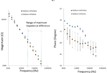
The impedance sensor with inflatable balloon was placed inside electrolyte-rich blood for impedance characterization and for determining the EIS measurements’ baseline. An input of 10 mV peak-to-peak AC voltage and frequency sweeping from 300 kHz to 100 Hz were delivered to the microelectrodes. The magnitudes and phases of the impedance were acquired at 20 data points per frequency decade. The baseline measurement is shown in comparison to the following ex vivo and in vivo measurements.
2.2.2.2 Inflation Pressure Characterization
surface. The EIS measurements revealed a baseline impedance of 70 kΩ at low frequency and more resistive behavior at a higher frequency, accompanied by -40 to -45 degrees of phase. At 7 psi, the inflated balloon enabled the microelectrodes to make contact with the vessel wall, resulting in a significant change in the impedance spectrum. At low frequencies, the magnitude of the impedance increased to 300 kΩ. At higher frequencies, the magnitude of the impedance decreased, as the vessel wall was more capacitive compared to saline, accompanied by a decrease in phase to -60 degrees at 100 kHz. At 9 psi, a slight decrease in magnitude and phase were observed, implicating a higher pressure applied by the balloon to the vessel wall, causing local deformation. Hence, our observations suggest that 7 psi is an optimal inflation pressure for EIS measurements with full surface contact and minimum applied force to the endoluminal surface. It is recognized that intravascular blood pressure is considerably higher than atmospheric pressure or the pressure in saline, so that the balloon in vivo may not be able to be
inflated to the same level in vitro.
Figure 2.7. Inflation pressure characterization in vitro (a) The balloon-inflatable
impedance sensor was inserted into the ex-vivo rabbit aorta. (b) Demonstration of balloon
inflation prior to impedance assessment. (c) Demonstration of intravascular balloon inflation.
frequencies above 30 kHz with phase. At 9 psi, the balloon was over-inflated representing a slight decrease.
2.3 Experiments and Results
2.3.1 Sample Preparation
In compliance with the Institutional Animal Care and Use Committee (IACUC) at the University of Southern California, four male New Zealand White (NZW) rabbits (10-week-old: mean body weight ~ 2 kg) were purchased from a local breeder (Irish Farms, Norco, CA). NZW rabbits are established as a model of atherosclerotic biology with plaques accessible to catheter interrogation. Two animals were fed a high-fat, high cholesterol diet (Newco® 1.5% cholesterol & 6% peanut oil). After 8 weeks, explants of aortas were interrogated for intravascular electrochemical impedance spectroscope (EIS). Another two animals were used for feasibility of in vivo EIS measurements.
2.3.2 Ex Vivo EIS Measurements in Fat-Fed NZW Rabbits
Figure 2.9. Ex-vivo EIS acquisition from explanted rabbit aorta and corresponding
[image:61.595.105.528.80.348.2]2.3.3 In Vivo EIS Measurements in NZW Rabbit
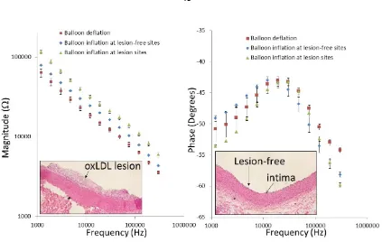
The deployment of the catheter-based balloon EIS sensor to interrogate carotid arteries of NZW rabbits has been further demonstrated (Fig. 2.10). The angiogram revealed the position of the catheter in relation of the EIS sensor. The impedance of in vivo measurements displayed a distinct phase spectrum compared to those of the ex vivo
findings (Fig. 2.9b) towards the lower frequency range. Both blood serum and vessel wall were more resistive, as reflected in a higher phase changes at -34.1±1.6 and -30.4±0.3 degrees, respectively (n = 6). However, the impedance spectra in the frequency range of 10 kHz to 300 kHz displayed a similar pattern to those of ex vivo (Fig. 2.9a). Balloon
inflation induced an increase in impedance and a decrease in phase towards the higher frequency range.
Figure 2.11. In-vivo EIS acquisition in the rabbit carotid arteries. Balloon-inflatable EIS
sensor packaged onto an in-house-built balloon catheter. The catheter was deployed through right carotid artery cut-down and the sensor made endoluminal contact under the fluoroscopic guidance. Inflation of the balloon resulted in a significant increase in the frequency-dependent impedance magnitude, from 10 kHz to 300 kHz, along with distinct phase characteristics.
2.4 Discussion
electrodes has been utilized, but showed limits in size as well as capability to detect small and non-homogenous plaques [10-12]. The concentric microelectrodes enabled highly sensitive EIS measurement of the electrochemical tissue properties at close proximity without interference from the surroundings.
The features of flexible and stretchable electronics have made real-time endoluminal assessment of lipid-rich plaques possible. Here, stretchable sensors have been characterized in terms of distinct changes in impedance and phase spectra in response to various pressures of balloon inflation (Fig. 2.9). Baseline EIS measurements before and after balloon inflation were established, followed by the comparison of EIS magnitudes in the presence or absence of lipid-rich plaques. The inflation of the balloon at 7 psi enabled the EIS sensors, in minimal contact with the endoluminal surface, providing significant differences in both impedance magnitude and phase changes at frequencies above 30 kHz (Fig. 2.9 and 2.11). Thus, the first intravascular impedance sensor that is both flexible and stretchable for in-vivo applications was demonstrated.
hyperlipidemia. Elevated EIS signals were reproduced in the oxLDL-rich, but not oxLDL-free, plaques [19].
An equivalent circuit model was provided here to illustrate the EIS measurement in intravascular tissue. Briefly, EIS measures intrinsic electrochemical properties of the tissue which depend on the chemical composition of the local tissue at the vicinity of the sensor. In particular, water content, electrolyte concentration and lipid content are a few of the most important factors affecting tissue impedance. Accumulation of oxLDL at the measurement site would significantly reduce water content, which is essentially the electrical conduction pathway, resulting in higher tissue impedance to electrical input signals, as well as more capacitive effect at high frequency. As demonstrated previously, it is feasible to establish a correlation between the status of the plaque and the resulting impedance in a certain frequency range, thus allowing accurate detection of the oxLDL-rich, mechanically unstable plaques.
In summary, this current study presents the use of a robust and innovatively designed balloon-inflatable catheter-based concentric EIS sensor that could be used for the detection of endoluminal electrochemical properties. The demonstrations on explants from fat-fed NZW rabbit aortas and carotid arteries via in-situ and in-vivo trials further
confirmed the link between endoluminal properties with pre-atherosclerotic plaques. The new features of real-time measurement as well as the stretching capability offer potential for clinical monitoring and integration with emerging flexible electronics for diagnosis and prognosis.
2.5 Conclusion
interrogation was demonstrated; providing a new intravascular strategy to identify high-risk plaques.
2.6 References
[1] Y. C. Fung, Biomechanics:Circulation, second edition ed.: Springer, 1997.
[2] J. Bamford, P. Sandercock, M. Dennis, J. Burn, and C. Warlow, "Classification and natural history of clinically identifiable subtypes of cerebral infarction,"
Lancet, vol. 337, pp. 1521-1526, 1991.
[3] Q. Rasheed, P. J. Dhawale, J. Anderson, and J. M. Hodgson,
"INTRACORONARY ULTRASOUND-DEFINED PLAQUE COMPOSITION - COMPUTER-AIDED PLAQUE CHARACTERIZATION AND
CORRELATION WITH HISTOLOGIC SAMPLES OBTAINED DURING DIRECTIONAL CORONARY ATHERECTOMY," American Heart Journal, vol.
129, pp. 631-637, Apr 1995.
[4] G. A. Rodriguez-Granillo, H. M. Garcia-Garcia, E. P. Mc Fadden, M. Valgimigli, J. Aoki, P. de Feyter, et al., "In vivo intravascular ultrasound-derived thin-cap
fibroatheroma detection using ultrasound radiofrequency data analysis," Journal of the American College of Cardiology, vol. 46, pp. 2038-2042, Dec 2005.
[5] H. Yabushita, B. E. Bourna, S. L. Houser, T. Aretz, I. K. Jang, K. H. Schlendorf, et al., "Characterization of human atherosclerosis by optical coherence
tomography," Circulation, vol. 106, pp. 1640-1645, Sep 2002.
[6] E. Regar, B. Hennen, E. Grube, D. Halon, R. L. Wilensky, J. Schneiderman, et al.,
resonance imaging probe. A multi-center safety and feasibility trial," European Heart Journal, vol. 27, pp. 515-515, Aug 2006.
[7] K. R. Aroom, M. T. Harting, C. S. Cox, R. S. Radharkrishnan, C. Smith, and B. S. Gill, "Bioimpedance Analysis: A Guide to Simple Design and Implementation,"
Journal of Surgical Research, vol. 153, pp. 23-30, 2009.
[8] K. R. Foster and H. P. Schwan, "Dielectric properties of tissues," Handbook of biological effects of electromagnetic fields, pp. 25-102, 1996.
[9] L. Marcu, M. C. Fishbein, J. M. I. Maarek, and W. S. Grundfest, "Discrimination of human coronary artery atherosclerotic lipid-rich lesions by time-resolved laser-induced fluorescence spectroscopy," Arteriosclerosis, Thrombosis, and Vascular Biology, vol. 21, pp. 1244-1250, 2001.
[10] T. Süselbeck, H. Thielecke, J. Köchlin, S. Cho, I. Weinschenk, J. Metz, et al.,
"Intravascular electric impedance spectroscopy of atherosclerotic lesions using a new impedance catheter system," Basic Research in Cardiology, vol. 100, pp.
446-452, 2005/09/01 2005.
[11] I. Streitner, M. Goldhofer, S. Cho, H. Thielecke, R. Kinscherf, F. Streitner, et al.,
"Electric impedance spectroscopy of human atherosclerotic lesions,"
Atherosclerosis, vol. 206, pp. 464-468, 2009.
[13] M. S. Brown and J. L. Goldstein, "Lipoprotein metabolism in the macrophage: implications for cholesterol deposition in atherosclerosis," Annual Review of Biochemistry, vol. 52, pp. 223-261, 1983.
[14] G. C. Cheng, W. H. Briggs, D. S. Gerson, P. Libby, A. J. Grodzinsky, M. L. Gray, et al., "Mechanical strain tightly controls fibroblast growth factor-2 release from
cultured human vascular smooth muscle cells," Circulation Research, vol. 80, pp.
28-36, 1997.
[15] Y. S. Kim, Z. S. Galis, A. Rachev, H. C. Han, and R. P. Vito, "Matrix metalloproteinase-2 and-9 are associated with high stresses predicted using a nonlinear heterogeneous model of arteries," Journal of Biomechanical Engineering, vol. 131, pp. 011009-011018, 2009.
[16] S. Ehara, M. Ueda, T. Naruko, K. Haze, A. Itoh, M. Otsuka, et al., "Elevated
levels of oxidized low density lipoprotein show a positive relationship with the severity of acute coronary syndromes," Circulation, vol. 103, pp. 1955-60, Apr 17
2001.
[17] S. Zeibig, Z. Li, S. Wagner, H. P. Holthoff, M. Ungerer, A. Bultmann, et al.,
"Effect of the oxLDL Binding Protein Fc-CD68 on Plaque Extension and Vulnerability in Atherosclerosis," Circulation research, vol. 108, pp. 695-703,
2011.
[18] G. Chinetti-Gbaguidi, M. Baron, M. A. Bouhlel, J. Vanhoutte, C. Copin, Y. Sebti,