AN INVESTIGATION OF FIBRE SIZING ON THE INTERFACIAL
STRENGTH OF GLASS-FIBRE EPOXY COMPOSITES
David Bryce1, Liu Yang2 and James L. Thomason3
Department of Mechanical and Aerospace Engineering, University of Strathclyde, Glasgow, UK
1
Email: david.bryce.100@strath.ac.uk, 2Email: l.yang@strath.ac.uk,
3
Email: james.thomason@strath.ac.uk
Keywords: Microbond, Interface, Epoxy Resin, Silane, Glass Fibre
Abstract
The fibre surface coating (or sizing) is one of, if not the, most crucial components involved in the manufacture of glass-fibres and plays a key role in determining the profitability, processability and both long- and short-term performance of the ultimate composite product. Given the importance of the fibre sizing to the optimisation of the interface, where the silane is the key component for interfacial strength, there is a critical need to improve our understanding of how this region is affected by fibre sizing. This paper focuses on an investigation into the role of a number of silanes typically used in fibre sizings in determining the interfacial shear strength (IFSS) of glass-fibre epoxy composites. The microbond test was used to characterise the effect of the fibre sizing on the IFSS. The work was conducted using silane-coated bare glass-fibres, silane-only sized fibres and fully-sized commercial fibres. It was found that sizing the fibres with silane increased the IFSS (with little significant difference between silanes), more so than with the fully-sized fibres. It was however considered that this apparent increase in IFSS may in fact be as a result of increased fibre tensile strength or an artefact of residual stress and static friction.
1. Introduction
The rapidly growing use of glass-fibre reinforced polymers (GFRP) in a wide range of industries, from automotive to wind turbine applications, means that the demand for development of new and improved composite materials that perform reliably over their lifetime whilst being subjected to high static and dynamic loads over a range of temperatures has never been higher. The fibre-matrix interface region is critical to the mechanical performance of a composite, thus optimisation of the stress transfer capability of this region is extremely important. The fibre sizing is a key parameter for controlling the stress transfer capabilities of the interface but also plays a critical role in defining most of the parameters which influence the long-term composite performance. Given the importance of the fibre sizing to the optimisation of the interface, where the silane is the key component for interface strength, there is a critical need to improve our understanding of how this region is affected by fibre sizing.
sizings on composite performance are widely recognized, there is a gap in the knowledge as to why
they work, beyond the fact that they do.
The present work focuses on examining fully-sized commercial glass-fibres, silane only sized fibres, and bare glass-fibres coated with silane to gauge the effect, if any, on the IFSS when used with a DGEBA-based epoxy resin system and whether any evidence can be presented for the theory that the success of the interface is of as much of a physical nature as it is a chemical one.
2. Experimental
2.1 Materials
[image:2.595.67.534.412.608.2]
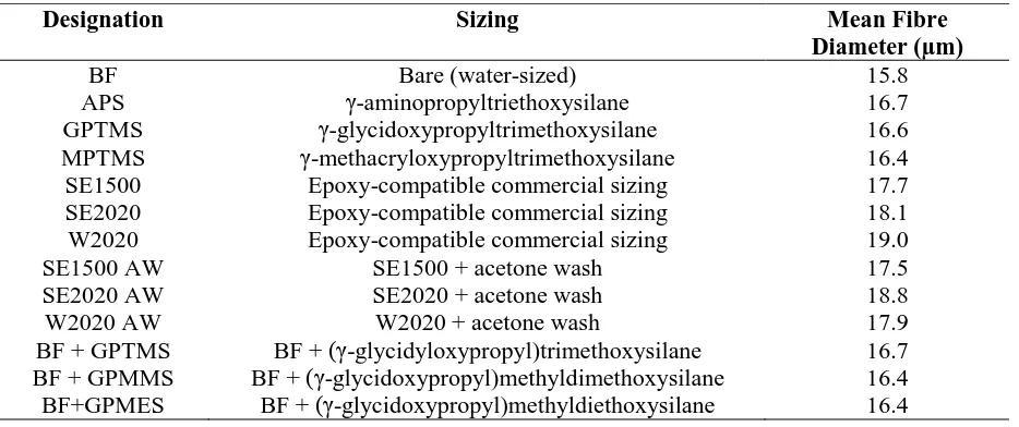
The experiments were conducted using a number of boron-free (and one borosilicate) E-glass fibres. Bare (water-sized) and silane-only sized fibres were taken from larger rovings supplied by Owens Corning. Fully-sized commercial fibres (Advantex® SE1500 and SE2020, HiPer-Tex™ W2020) were taken from larger rovings supplied by 3B. The epoxy resin systems used were Araldite® 506 and D.E.R.™ 332 both with triethylenetetramine, technical grade 60%, (TETA) as a curing agent supplied by Sigma Aldrich. Both are bisphenol-A diglycidyl ether-based and the 506 resin also contains a reactive diluent. Owens Corning bare (water-sized) fibres were coated with 1% solutions of γ-glycidyloxypropyltrimethoxysilane (Sigma Aldrich), γ-glycidoxypropylmethyldimethoxysilane (Flurochem) and γ-glycidoxypropylmethyldiethoxysilane (Fluorochem). The fibres used for the investigation are summarized in Table 1.
Table 1: Glass Fibre Summary
Designation Sizing Mean Fibre
Diameter (µm)
BF Bare (water-sized) 15.8
APS γ-aminopropyltriethoxysilane 16.7
GPTMS γ-glycidoxypropyltrimethoxysilane 16.6
MPTMS γ-methacryloxypropyltrimethoxysilane 16.4
SE1500 Epoxy-compatible commercial sizing 17.7
SE2020 Epoxy-compatible commercial sizing 18.1
W2020 Epoxy-compatible commercial sizing 19.0
SE1500 AW SE1500 + acetone wash 17.5
SE2020 AW SE2020 + acetone wash 18.8
W2020 AW W2020 + acetone wash 17.9
BF + GPTMS BF + (γ-glycidyloxypropyl)trimethoxysilane 16.7 BF + GPMMS BF + (γ-glycidoxypropyl)methyldimethoxysilane 16.4 BF+GPMES BF + (γ-glycidoxypropyl)methyldiethoxysilane 16.4
2.2 Sample Preparation
The epoxy resin and curing agent were mixed to the stoichiometric ratio (≈14pph) and degassed for 10 minutes to remove air trapped during mixing and improve the homogeneity of the mixture. Individual fibres were removed from bundles (in turn removed from the roving) and applied across 20mm gauge length card windows, attached first with double-sided tape then secured with superglue. A length of steel wire (Ø=125µm) was used to apply resin to the fibres in order to form axisymmetric micro-droplets suitable for testing. Each application produced a number of micro-droplets. The wire was touched to the fibre twice for each sample in order to choose the most suitable droplet following optical microscopy. The samples were then cured at 60°C for 1 hour followed by 120°C for 2 hours with a consistent 2°C/min temperature ramp used throughout. Once cured, the droplets were examined under an optical microscope at 200x magnification with ideal, axisymmetric droplets chosen for testing. The fibre diameter, length of the droplet (embedded length) and droplet diameter were then measured. Multiple images were collected for each sample and droplets with diameters of 40-80µm chosen to maintain an approximate droplet size throughout. These measurements are required in order to calculate the IFSS using Equation 1.
𝜏=𝜋𝐷𝐹𝑚𝑚𝑚
𝑓𝐿𝑒 (1)
Where τ is the interfacial shear strength, Fmax is the maximum load, Df is the diameter of the fibre and
Le is the embedded length.
2.3 The Microbond Test
[image:3.595.140.460.531.667.2]A generally accepted manifestation of adhesion is the mechanically measured interfacial shear strength (IFSS)[2]. Over the years a number of experimental techniques have been developed and studied in order to assess the IFSS such as the microbond test and the single fibre pull-out test [3]. It is also known that the IFSS can be influenced by chemicals, such as silane coupling agents. This has in turn led to a number of investigations surrounding both glass and carbon fibre-reinforced polymer composites using the microbond test method [4-5]. In the present work, the effect of various silane coupling agents and full sizings on the IFSS of the composite was investigated using the microbond test. While it is debated whether micromechanical testing methods do in fact provide a true measure of adhesion there can be no doubt that they serve as a useful tool for screening various combinations of fibre and matrix and work as a reliable comparative method.
Figure 1: Microbond testing apparatus
force and the debonding of the fibre from the surrounding matrix. Once placed in the rig, shearing blades were moved with micrometers in order to secure the sample. Care was taken to avoid damaging or severing the sample prior to testing. The details of the sample were then inputted into the Instron software and the test began at a rate of 0.1mm/min using a 10N load cell. Successful sample debond exhibited a slight curve at the peak force as opposed to a sharp drop in instances of fibre fracture. A further indication of a successful sample was the force beginning to ramp again as a result of frictional forces. Results were excluded for samples where the fibre fractured prior to a successful debond occurring.
3. Results
[image:4.595.137.457.311.509.2]The microbond testing results was based around three pre-coated silane-only fibres, three commercial fully-sized fibres and three bare glass fibres coated in-house. Of particular interest is the plot of maximum load against embedded area allowing the spread of the data to be easily assessed. Figure 2 shows a typical plot, exhibiting the scatter in data characteristic to the microbond test.
Figure 2: Maximum load vs embedded area for SE1500 with 506 resin
Figure 3: Comparison of glass fibre sizings
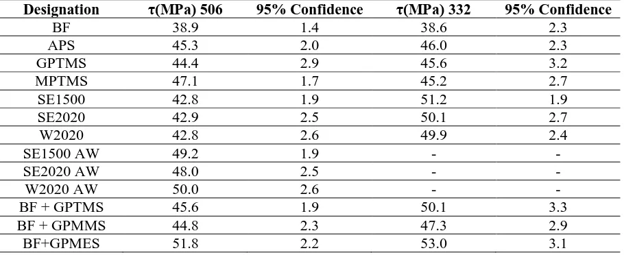
Following treatment with silane, each of the fibres showed increased IFSS over bare glass fibres. The fibres which were coated with GPTMS in-house showed comparable results to those which were received pre-coated. There was little significant difference (within confidence limits between) GPTMS and GPMMS with GPMES exhibiting improved results for both resin systems.
Figure 4: Comparison of bare glass fibres before and after treatment with silane
[image:5.595.134.467.410.627.2]Figure 5: Comparison of fully-sized fibres following acetone treatment
The microbond testing results are summarised in Table 2:
Table 2: Summary of Microbond Testing Results
Designation τ(MPa) 506 95% Confidence τ(MPa) 332 95% Confidence
BF 38.9 1.4 38.6 2.3
APS 45.3 2.0 46.0 2.3
GPTMS 44.4 2.9 45.6 3.2
MPTMS 47.1 1.7 45.2 2.7
SE1500 42.8 1.9 51.2 1.9
SE2020 42.9 2.5 50.1 2.7
W2020 42.8 2.6 49.9 2.4
SE1500 AW 49.2 1.9 - -
SE2020 AW 48.0 2.5 - -
W2020 AW 50.0 2.6 - -
BF + GPTMS 45.6 1.9 50.1 3.3
BF + GPMMS 44.8 2.3 47.3 2.9
BF+GPMES 51.8 2.2 53.0 3.1
4. Discussion
It is evident that the application of silane, or in fact any sizing, increases the interfacial tenacity of the composite. Given that there is little significant difference between the silane coatings, it is reasonable to suggest that the improvement may be of a (at least partially) physical nature as much as a chemical one. It would be expected that sizings (commercial and GPS-based) formulated to give improved results with epoxies (thus containing reactive groups) would give uniformly improved performance, though this was not always the case. In addition to chemical interactions, it is important to consider the physical interactions that may contribute to a proportion of the measured IFSS.
[image:6.595.66.521.394.580.2]Figure 6: SEM of micro-droplet cure shrinkage
This dimensional shrinkage can result in radial compressive stresses “gripping” the fibre. In addition, static friction may be increased through the application of a silane/sizing compared to bare glass. In their review of the literature Kalantar and Drzal found that Aramid showed improved interfacial properties following a roughening of the surface, though it would be interesting to study this further in regards to glass-fibre/epoxy composites [7].
When used with the Araldite 506 epoxy, the fully-sized fibres exhibited marginally weaker interface properties than that of the silane-only sized fibres. It is possible that the acetone treatment removes additives that, while essential for processing and production, may also in fact detract from the interfacial properties of the composite.
While the results for both resin systems remained more or less consistent for the pre-coated silane-only fibres, the D.E.R. 332 resin system exhibited superior IFSS when used in conjunction with commercially-sized fibres and with those coated in-house. Both epoxy resins are of the DGEBA, with the Araldite 506 containing a reactive diluting agent and D.E.R. 332 being a single resin. In general, the viscosity of the D.E.R. resin resulted in slightly larger droplets that, while still within the imposed 40-80µm diameter limit, resulted in a slightly larger embedded area.
Though there is debate on whether micromechanical testing methods are realistic approximations of the true interface of the composite, the microbond test (among others) remain effective methods for screening and comparing various sizings and allow for almost any fibre and matrix combination to be used[8-9].
5. Conclusions
apparent IFSS involve cure shrinkage of the droplet “gripping” the fibre, with thermal residual stress and static friction contributing to a significant portion of the measured IFSS [11-12].
Further lines of research into this area such as tensile testing of all the fibres involved would be beneficial to draw a correlation between fibre tensile strength and IFSS. Of particular interest is the acetone washed commercial fibres and whether they exhibit a noticeable depreciation in strength following the treatment. Further work will also involve isolating the fibre surface through the application of an inert coating prior to applying resin micro-droplets.
Acknowledgments
The authors would like to extend thanks to Suzlon Energy Ltd. and the University of Strathclyde as the sponsors of this project.
References
[1] J. L. Thomason, Glass Fibre Sizings: A Review of the Scientific Literature. James L. Thomason, 2012.
[2] B. Miller, P. Muri, and L. Rebenfeld, “A Microbond Method for Determination of the Shear Strength of a Fiber/ Resin Interface,” Composites Science and Technology, vol. 28, no. 1, pp. 17–32, 1987.
[3] P. J. Herrera-Franco and L. T. Drzal, “Comparison of methods for the measurement of fibre/matrix adhesion in composites,” Composites, vol. 23, no. 1, pp. 2–26, 1992. [4] S. Sockalingam and G. Nilakantan, “Fiber-Matrix Interface Characterization through the
Microbond Test,” International Journal of Aeronautical and Space Sciences, vol. 13, no. 3, pp. 282–295, 2012.
[5] H. Wang, H. Wang, W. Li, D. Ren, and Y. Yu, “An improved microbond test method for determination of the interfacial shear strength between carbon fibers and epoxy resin,” Polymer Testing, vol. 32, no. 8, pp. 1460–1465, 2013.
[6] L. Yang and J. L. Thomason, “Development and application of micromechanical techniques for characterising interfacial shear strength in fibre-thermoplastic composites,” Polymer Testing, vol. 31, no. 7, pp. 895–903, 2012.
[7] J. Kalantar and L. T. Drzal, “The bonding mechanism of aramid fibres to epoxy matrices Part 1: A review of the literature,” Journal of Materials Science, vol. 25, no. 10, pp. 4186–4193, 1990.
[8] P. Zinck, H. D. Wagner, L. Salmon, and J. F. Gerard, “Are microcomposites realistic models of the fibre/matrix interface? I. Micromechanical modelling,” Polymer, vol. 42, pp. 5401–5413, 2001.
[9] P. Zinck, H. D. Wagner, L. Salmon, and J. F. Gerard, “Are microcomposites realistic models of the fibre/matrix interface? II. Physico-chemical approach,” Polymer, vol. 42, pp. 6641–6650, 2001.
[10] S. P. Reilly and J. L. Thomason, “Effects of silane coating on the properties of glass fibre and glass fibre reinforced epoxy resin,” Proceedings of the 14th European Conference on
Composite Materials 7-10 June 2010, Budapest, Hungary, 2010.
[11] J. L. Thomason, L. Yang, D. Bryce, and R. Minty, “An exploration of the relationship of chemical and physical parameters in the micromechanical characterisation of the apparent interfacial strength in glass fibre epoxy systems,” IOP Conference Series: Materials Science and Engineering, vol. 139, p. 12048, 2016.