PAPER
Cite this:Lab Chip, 2016,16, 3548
Received 12th July 2016, Accepted 27th July 2016
DOI: 10.1039/c6lc00884d
www.rsc.org/loc
Transitioning from multi-phase to single-phase
microfluidics for long-term culture and treatment
of multicellular spheroids
†
Kay S. McMillan,
aMarie Boyd
band Michele Zagnoni*
aWhen compared to methodologies based on low adhesion or hanging drop plates, droplet microfluidics offers several advantages for the formation and culture of multicellular spheroids, such as the potential for higher throughput screening and the use of reduced cell numbers, whilst providing increased stability for plate handling. However, a drawback of the technology is its characteristic compartmentalisation which limits the nutrients available to cells within an emulsion and poses challenges to the exchange of the en-capsulated solution, often resulting in short-term cell culture and/or viability issues. The aim of this study was to develop a multi-purpose microfluidic platform that combines the high-throughput characteristics of multi-phase flows with that of ease of perfusion typical of single-phase microfluidics. We developed a versatile system to upscale the formation and long-term culture of multicellular spheroids for testing anti-cancer treatments, creating an array of fluidically addressable, compact spheroids that could be cultured in either medium or within a gel scaffold. The work provides proof-of-concept results for using this system to test both chemo- and radio-therapeutic protocols usingin vitro3D cancer models.
1. Introduction
Cancer continues to be a major problem worldwide, with a prediction that the number of new cases will reach over 20 million by 2030.1Although there has been an increase in the number of anticancer chemotherapies developed over the past decade, their success rate has been poor, with less than 10% of anticancer drugs progressing to clinical trials.2,3 Fur-thermore, improvements are required in radiation therapy for certain types of cancer, such as glioblastoma, where treatment failure remains high.4 To this end, more physiologically rele-vant preclinical cancer models than those based on cancer cell monolayers can lead to develop more efficacious thera-pies. Multicellular tumour spheroids are in vitro 3D cancer models which can mimic the heterogeneous cell composition and the microenvironmental features seen in in vivo tu-mours,3,5 representing an ideal candidate model during drug discovery.6,7 However, standard methods for the formation and study of multicellular tumour spheroids (e.g. spinner flask, hanging drop and low adhesion plates) are generally la-bour intensive and low-throughput.3 Therefore, the
develop-ment of robust and automatable microfluidic technologies based on spheroid models has the potential to facilitate the adaptation of existing screening protocols and increase the data throughput when testing anticancer therapies.
In recent years, droplet microfluidics techniques8 have been increasingly used for the formation and culture of multicellular spheroids and organoids.9–16These methods in-volve the encapsulation of cells or cell aggregates within an aqueous (or gel) droplet in an oil phase, with the aqueous–oil interface being biocompatible and presenting non-adhering characteristics.17,18 In comparison to established methods, such as those based on spinner flasks or hanging drops, cell encapsulation in aqueous/gel-in-oil droplets prevents expo-sure of cells to shear stress19and provides a stable environment that is insensitive to mechanical perturbation, respectively.6 Arguably, the greatest advantage that droplet microfluidics can offer is that of significantly increasing the throughput of information, where assays can be developed allowing the for-mation of up to 1000 spheroids per device.16 However, a drawback of emulsion-based methods for cell culture is compartmentalisation, where each droplet acts as an environ-mentally isolated experiment, thus limiting the volume of nu-trients available to the cells and concentrating build-up of waste products,11,12,20,21both of which have a detrimental ef-fect on cell viability over time. Other limitations when work-ing with emulsion techniques include the inability to directly perfuse the dispersed phase content and to prevent the parti-tion of encapsulated substances (i.e. lipophilic drugs) into
aCentre for Microsystems and Photonics, Electronic and Electrical Engineering,
University of Strathclyde, Glasgow, G1 1XW, UK. E-mail: michele.zagnoni@strath.ac.uk
bStrathclyde Institute of Pharmacy and Biomedical Sciences, University of
Strathclyde, Glasgow, G4 0RE, UK
†Electronic supplementary information (ESI) available. See DOI: 10.1039/ c6lc00884d
Open Access Article. Published on 27 July 2016. Downloaded on 13/09/2016 15:23:16.
This article is licensed under a
Creative Commons Attribution 3.0 Unported Licence.
the oil phase. Therefore, a microfluidic approach capable of overcoming these limitations would aid long-term cell culture after their encapsulation in emulsions and the development of multi-step anticancer treatment tests (e.g.repeated injec-tion of drugs at specific time points after spheroid formainjec-tion over weeks of culture).
It has been previously shown that biocompatible fluoro-surfactants can be used for the formation and culture of spheroids within single and double emulsions.6,9 This is obtained due to the polyethylglycol (PEG) head of the surfac-tant used, which creates a non-adherent water/oil interface, resulting in cancer cells aggregating within the emulsion to form compact spheroids. Additionally, we have shown that the ability to regulate the microenvironmental factors during spheroid culture within emulsions is a key aspect to ensure their viability and to control cell quiescence,6 elements that affect spheroid response to radiotherapeutic investigation. Therefore, a microfluidic approach that integrates the compartmentalisation and high-throughput features of drop-let microfluidics with the ease of perfusion of single-phase laminar flows would offer a universal microfluidic platform for screening multicellular spheroids.
The fluorosurfactants used in the previous studies are known to produce stable and long lasting emulsions when water or salt solutions were used as the dispersed phases.18 However, it has been reported that molecules, such as bovine albumin serum (BSA), can destabilise the emulsion interface and increase their chance of coalescence.18This aspect could explain the need for microfluidic designs that keep emul-sions from contacting each other when encapsulating cells.22 Therefore, an approach that exploits induced interface insta-bility to create controlled emulsion coalescence could provide a solution to the compartmentalization issues during cell cul-ture with droplet microfluidics.
In this study, we present a microfluidic system that allows both chemotherapy and radiotherapy protocols to be investi-gated in an array of multicellular spheroids over weeks of cul-ture. The procedure is based on the controllable coalescence of multiple emulsion interfaces after the initial spheroid for-mation, enabling injection of fresh media and drugs to be de-livered at desired time points. The system was used to dem-onstrate culture of spheroids under various experimental conditions (e.g.with and without the use of 3D matrix scaf-folds). Using a human glioma cell line (UVW),6 we have characterised the growth rate of spheroids, their response to X-ray irradiation and to anticancer compounds, showing the wide range of applicability of the proposed microfluidic sys-tem to develop powerful screening assays.
2. Experimental
2.1. Device preparation
Microfluidic devices were fabricated using standard soft- and photo-lithography techniques as previously described.6 Briefly, master templates were produced using SU8
photore-sist (3000 series, MicroChem, US) onto a silicon wafer follow-ing the manufacturer's protocol, achievfollow-ing a final resist thick-ness of 200μm. The resist was exposed through a photomask (JD Photo-Tools, UK) to UV light and was developed in Micro-Posit EC solvent (Rohm and Haas, US). Polydimethylsiloxane (PDMS) was poured onto the silicon master at a 10 : 1 ratio of base to curing agent, degassed in a vacuum desiccator cham-ber and cured at 80°C for at least 2 hours. To prevent PDMS adhesion to the silicon master, the wafer's surface was silanised by vapour deposition of 1H,1H,2H,2H -perfluorooctyl-trichlorosilane (Sigma Aldrich, UK) for 1 hour. The PDMS de-vices were then peeled from the mould, cut to the desired size, and holes were punched using G21 needles to obtain in-let and outin-let ports. PDMS devices were then cleaned and ir-reversibly bonded to glass microscope slides using oxygen plasma. Bonded devices were then treated with undiluted Aquapel (PPG Industries) to obtain fluorophilic microchannel surfaces.
2.2. Cell culture and spheroid formation
A human glioblastoma cell line (UVW) developed in house was utilised.23UVW cells were maintained in an atmosphere of 5% CO2 and incubated at 37 °C, in minimum essential
medium (MEM), containing 10% (v/v) of foetal calf serum (FCS), L-glutamine (200 mmol l−1), penicillin/streptomycin
(100 U ml−1) and Fungizone (2 μg ml−1). Medium and addi-tional supplements were purchased from Invitrogen, UK.
2.3. Microfluidic protocols
FC-40 (3 M) fluorinated oil with 2% wt block copolymer fluorosurfactants (designed by the Weitz Group at Harvard and supplied by RAN Biotechnologies, catalogue# 008-FluoroSurfactant, Beverly, MA, USA) was used as the continu-ous phase in all experiments. To better visualise the destabilisation of emulsion interfaces, an aqueous phase containing 100 μM of calcein (Sigma Aldrich, UK) in either water or medium was used. For spheroid experiments, a cell suspension at a concentration of 3 ×10⁶ cells per ml in me-dium was used. Polytetrafluoroethylene (PTFE) tubing (Cole Parmer) was used to connect syringes to the inlet ports of the microfluidic device and syringe pumps (AL-1000, World Preci-sion Instruments, Hertfordshire) were used to inject the phases. Two device structures were used: one to quantify emulsion coalescence in a large chamber (Fig. S1 in ESI†)24 and another to carry out spheroid experiments (Fig. 2), based on a modified version of a previously reported design.25–27 Medium in oil (M/O) droplets (with or without cells) were formed at a T-junction and then stored within the device. For spheroid culture, medium was refreshed every 2 days and de-vices were incubated after seeding at an atmosphere of 5% CO2and at 37°C. For spheroid withdrawal medium was
dis-pensed through the outlet to displace spheroids from their traps.
Open Access Article. Published on 27 July 2016. Downloaded on 13/09/2016 15:23:16.
This article is licensed under a
2.4. Alginate bead preparation
Sodium alginate (Sigma Aldrich, UK) was dissolved into me-dium at a concentration of 2% (w/v), heated to 50 °C for 2 hours and stored at 4°C prior to use. The sodium alginate solution was filtered through a 0.2 μm filter to remove any particulate after storing it in a fridge. A cell suspension of 3× 10⁶cells per ml in the sodium alginate mixture was used as a dispersed phase. To carry out gelation of the alginate drop-lets, a 4% (w/v) solution of calcium chloride in medium was filtered through a 0.2μm filter to remove any particulate and perfused through the device. After droplet gelation, the cal-cium chloride solution was replaced by medium which was subsequently refreshed every 2 days to replenish nutrients to the spheroids.
2.5. Viability staining of spheroids
Spheroids were stained for cell viability using fluorescein diacetate (FDA) and propidium iodide (PI) (Sigma Aldrich, UK). The staining solution, containing 20 μg ml−1 of PI and
8 μg ml−1 of FDA, was loaded into a syringe and perfused
through the device for approximately 20 minutes. Spheroids were incubated in the staining solution for approximately 15 minutes then washed with phosphate buffer saline (PBS) be-fore imaging.
2.6. Radiation treatment of spheroids
Spheroids were allowed to form and cultured in M/O droplets as previously described6and irradiated with a single dose of 8 Gy using a PXI X-Rad 225C X-irradiator, set to a dose rate equating to 2.2 Gy per min (RPS Services, Surrey, UK). Subse-quently, both control and irradiated spheroids were cultured as previously described and their size monitored for up to 12 days.
2.7. Dosimetry measurements
For calibration purposes, a UNIDOS® E universal dosimeter with a CC04 ionisation chamber (PTW, Germany) was used to measure the amount of radiation that was absorbed by a glass slide and a PDMS slab (∼5 mm thick) respectively, as well as by a PDMS/glass microfluidic device.
2.8. Drug treatment of spheroids
Cisplatin (Sigma Aldrich, UK) was dissolved in 0.9% sodium chloride solution to make a stock solution of 1 mM. Doxoru-bicin (Sigma Aldrich, UK) was dissolved in deionised water to make a stock solution of 5 mM. For treatment, the cisplatin stock solution was diluted to 50μM with complete medium and the doxorubicin stock solution was diluted to 4μM with complete medium. Spheroids were allowed to form and cul-tured in M/O droplets as previously described and perfused for 30 minutes with the desired anticancer compound. After 24 hours, the incubated drug solution was washed from the device and replaced by medium to replenish nutrient and cre-ate a favourable growth condition for the spheroids. Subsequently,
both control and cisplatin-treated or doxorubicin-treated spheroids were cultured for up to 12 or 14 days to assess treatment efficacy.
2.9. Spheroid growth measurement
Spheroid growth was monitored over time by measuring the increase of their diameter after day 1 of culture (when com-pact spheroids were obtained) with brightfield microscopy, using a Zeiss inverted microscope (Axiovert A1) and a Labview controlled Dalsa Genie CMOS HM1024 camera. Spheroid dimensions were estimated using ImageJ by mea-suring the longest and shortest diameters (D1 and D2, re-spectively) to calculate their average diameter. The Mann Whitney test was used to evaluate the statistical difference between experiments (significant difference between groups obtained forpvalue≤0.05).
3. Results and discussion
The device geometry and protocols developed in this work rely on the combination of a microfluidic passive channel network that enables M/O droplets, encapsulating a cell sus-pension, to be trapped within an array of sites and the con-trolled rupture of the emulsion interfaces once compact spheroids were formed within the array. Experiments were firstly conducted to determine the causes of emulsion coales-cence. Subsequently, using the same device structure, micro-fluidic protocols were established for spheroid long-term cul-ture using both complete medium (matrix-free condition) and calcium alginate gels (scaffold-supported condition) whilst performing periodic medium exchange. Finally, the system was validated for carrying outin vitroradiotherapeutic and chemotherapeutic assays using spheroids.
3.1. Factors influencing emulsion coalescence
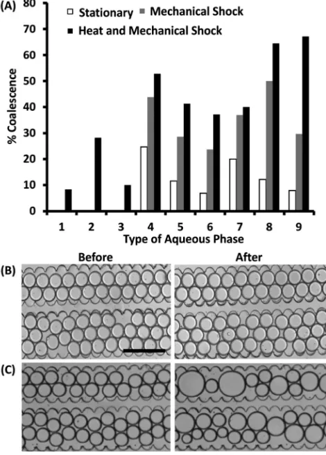
The fluorosurfactants used in this study are known to pro-duce emulsions with robust,18long-lasting28and biocompati-ble oil/water interfaces, thus enabling favourabiocompati-ble conditions for the culture of cells, organisms20and multicellular spher-oids.6 However, when emulsions containing cell medium were incubated in close contact with each other and in static conditions, we observed undesired and increasing emulsion coalescence over a period of time ranging from tens of mi-nutes to a few hours, a condition that never occurred when encapsulating deionised water solutions. Therefore, we inves-tigated the factors that compromised emulsion stability by testing emulsion coalescence when using various aqueous phases that are typically required for the culture of mamma-lian cells. In addition, these experiments were also carried out investigating the effects on coalescence due to tempera-ture variation and mechanical shocks, practical factors in-volved in the long-term culture of cells and when handling microfluidic devices from cell incubators to microscope stages or plate readers. The aqueous phases included deionised water, PBS, MEM without additives, MEM with
Open Access Article. Published on 27 July 2016. Downloaded on 13/09/2016 15:23:16.
This article is licensed under a
individual additives and the complete cell medium used for cell culture of UVW cells (i.e.containing growth factors, anti-fungals, antibiotics,etc.).
To carry out this investigation, aqueous droplets in oil were formed and stored within a microfluidic chamber (∼1300 aqueous droplets per chamber) that allowed for emul-sion interfaces to be in close contact with each other (Fig. S1 in ESI†). The number of non-coalesced emulsions in the chamber upon initial loading was compared to the number of non-coalesced emulsions after 30 minutes under three conditions: while stationary, within an incubator at 37°C, or after a‘mild’mechanical shock produced by placing the de-vice on a microscope stage holder. This analysis provided the resulting percentage of emulsion coalescence for each case (Fig. 1) which was calculated as follows:
(1)
whereNDroplets (t = 0) equals the number of droplets at the start of the experiment andNDroplets(t=x)equals the number of droplets after a certain period of time. As expected, and in agreement with the literature, when using deionised water, PBS or MEM without supplements (1–3 in Fig. 1A), no coales-cence was observed except for the case of incubating droplets at 37°C. In contrast, when medium was used in combination with any of the supplements (4–9 in Fig. 1A), droplet coales-cence increased significantly even when the device was kept stationary and at ambient temperature. In these conditions, a mild physical shock (i.e.produced by placing the device on a microscope holder) was observed to increase the chance of coalescence by twice as much with respect to its stationary state. As expected, storing the device inside a cell incubator showed a progressive increase in coalescence from deionised water to PBS and from MEM to full medium. Above all, addi-tives typically used for cell culture, such as FBS, Fungizone and penicillin/streptomycin, strongly enhanced the instability of the emulsion interface in comparison to minimum essen-tial medium alone. As previously described for emulsions made using the same fluorosurfactants, additive molecules within the encapsulated phase, such as bovine serum albu-min (BSA),18 can interact with the surfactant monolayer at the emulsion interface, resulting in the displacement of the surfactants and leading to emulsion coalescence. Relevant to our study, one of the components of FBS is albumin and it can be assumed that this molecule, in combination with other supplements, could be responsible for the increased emulsion instability observed. However, due to the complex-ity and variety of additives in full cell medium, further inves-tigation needs to be carried out to identify other potential molecular causes related to coalescence.
3.2. Device operation principle: from emulsions to single phase microfluidics
The analysis presented in the previous section highlighted how molecules typically present in cell culture medium can
facilitate emulsion coalescence. Here, we exploit this aspect to our advantage. We present a two steps procedure whereby droplet microfluidics protocols were first used to encapsulate cells within emulsions and allowed their transformation into multicellular spheroids in compartmentalized growth sites in parallel. Subsequently, within the same microfluidic struc-ture, perfusion of complete medium replaced the continuous oil phase and resulted in the controlled rupture of the emul-sion interfaces, thus enabling subsequent medium exchange, guaranteeing long term culture and the delivery of chemicals to the pre-formed spheroids at the desired time points.
Fig. 1 Effect of the aqueous phase composition on coalescence of contacting emulsions. (A) Bar chart showing the percentage of coalesced emulsions for different aqueous phases in varied experimental conditions. An initial number of approximately 1000 emulsions (NDroplet(t= 0) = 1000 in eqn (1)) were considered for each
case (1 trial per case is shown). After droplet formation, emulsions were stored in a microfluidic chamber: (white) devices were kept stationary on a microscope stage for 30 min; (grey) devices were manually placed on a microscope stage producing a mild mechanical shock; (black) devices were transferred from a cell incubator at 37°C to the microscope stage after 30 min. The %Coalescence value was
calculated using eqn (1). Representative images of coalescence of droplet in oil-surfactants within a microfluidic chamber using deionised water (B) and complete medium (C) before and after placing the device on a microscope. 1 is deionised water; 2 is PBS; 3 is MEM; 4 is MEM with FBS; 5 is MEM with Fungizone; 6 is MEM with Pen/Strep; 7 is MEM with FBS and Pen/Strep; 8 is MEM with FBS and Fungizone and 9 is MEM with all of the supplements for UVW cell culture. The scale bar is 350μm.
Open Access Article. Published on 27 July 2016. Downloaded on 13/09/2016 15:23:16.
This article is licensed under a
[image:4.595.311.546.46.374.2]For this, a microfluidic design was developed based on the work by Boukellalet al.25and Vanapalli et al.26,27,29 The microfluidic channel network consisted of a serial array of traps allowing for the sequential storage of M/O droplets (Fig. 2A). When a plug approached an empty trapping site, it followed the path with the smallest fluidic resistance and tered a round chamber within which its surface tension en-ergy was minimised, with the emulsion changing its shape from an oblong plug to a round droplet (Fig. 2B 1–2). A sub-sequent plug would bypass the trapped droplet without
coa-lescence and slot in the next available empty round chamber (Fig. 2B 3–4) until all the trapping sites were occupied (Movie S1†). At this point, only the continuous phase was flown through the device channels to remove any non-trapped droplet and exited the device both from the array and the by-pass channel outlets (3A and 4A in Fig. 1). In this condition, tubing was detached from the device with the emulsions remaining‘locked’into the round chambers, enabling spher-oid incubation for as long as required.
To induce rupture of the emulsion interfaces, a solution of full medium (containing molecules that could destabilise the emulsion interface as previously discussed) was injected into the device after 24 hours. This formed a long plug that pushed the oil left in the microchannel towards the outlets without displacing the trapped droplets (Fig. 2C 1–4). Subse-quently, coalescence of the trapped droplets with the long plug was observed within minutes (Fig. 2C 5–8 and Movie S2†). As a control experiment, when water was used as the aqueous phase, no coalescence of the plug with the trapped droplets occurred (not shown).
In contrast to previous reports,27,30by following this proto-col, emulsion coalescence occurred without the need to alter the surfactant concentration in the oil phase and with a rela-tively simple procedure that did not require the use of active PDMS valves or electrocoalescence strategies.31,32 Whilst for organisms such as C. Elegans low concentration of surfac-tants (0.001% w/v) are typically tolerated,30when using mam-malian cell suspensions the biocompatibility guaranteed by the PEG-fluorocarbon surfactants (2% w/v) is essential for long term culture and to provide a non-adherent interface which is required to induce cellular aggregation.6
3.3. Formation and culture of multicellular spheroids
We have previously demonstrated how emulsion technologies can be exploited to control the level of proliferation and qui-escence of multicellular spheroids.6However, the major limi-tation to scaling up the techniques developed was the need for accessing and exchanging the emulsion inner phase, proce-dures that were carried out manually. In this work, following the protocol detailed in section 3.2, we demonstrate proof-of-concept of in vitro chemotherapy and radiotherapy assays within a single, scalable and automatable microfluidic plat-form, enabling direct access to the cultured spheroid micro-environment to be obtainedviamicrofluidic perfusion.
Here, spheroids were formed in plugs containing a sus-pension of glioma cells and these were trapped within the storage array. In brief, a cell suspension incubated in a rest-ing droplet sedimented at the bottom of the droplet on the biocompatible PEG layer at the medium/oil interface. Due to the non-adherent nature of the PEG head of the fluoro-surfactants, cells tended to aggregate into a compact spher-oid structure.6 Droplet trapping efficiency was 100%, with each droplet encapsulating between 60 and 160 cells for the cell concentration used (Fig. 3). This variation in cell number within droplets is due to the fact that particle
Fig. 2 Microfluidic protocol for emulsion production, storage and interface disruption. (A) Layout of the microfluidic device: aqueous phase-oil plugs are generated at a T-junction; 1A is the oil phase in-let; 2A is the aqueous phase inin-let; 3A is the bypass channel outin-let; 4A is the outlet and 5A is the chamber array. (B) Schematic diagram show-ing the plug trappshow-ing mechanism: a plug approaches an empty storshow-ing chamber and remains trapped within it (1 and 2); subsequent plugs by-pass the occupied round chamber and enter in the next available trap (3 and 4) (Movie S1†). (C) Time-lapse of brightfield & fluorescent im-ages (1 to 5) and fluorescent imim-ages (6 to 8) of a long plug containing medium with calcein interacting with emulsion interfaces and eventu-ally leading to interface rupture. Images 1 to 4 show the long plug en-tering the serial array and coming into contact with the droplets in the traps without initial coalescence. Images 5 to 8 show the sequential rupture of the interface between the stored droplets and plug. Calcein is then observed to diffuse inside the stored droplet following emul-sion interface rupture (Movie S2†). The scale bar is 400μm.
Open Access Article. Published on 27 July 2016. Downloaded on 13/09/2016 15:23:16.
This article is licensed under a
[image:5.595.51.283.44.397.2]encapsulation in emulsions follows a Poisson distribution.33 Additionally, we sometimes observed a fluctuation in the flow due to cell clustering that influenced the number of cell en-capsulated per M/O droplet. After trapping, droplets containing cells were incubated for approximately 24 hours at 5% CO2 and at 37°C, allowing for the formation of
com-pact cell aggregates, as previously described.6 During this step, the use of PEG-fluorocarbon surfactants was essential to guarantee a non-adherent substrate, thus inducing cell aggre-gation. Although a slight shrinkage of the M/O droplets was observed over this time (which can be compensated for by in-creasing the humidity level during incubation), due to me-dium evaporation, the emulsions did not displace from the traps and no detrimental effects were produced to spheroid viability.
After 1 day of culture, compact spheroids were obtained, ranging from 40 to 150μm in diameter depending on the ini-tial cell number within the M/O droplet (Movie S3†). Overall, spheroid size variation within a device can be advantageous when performing screening assays as, due to the proportion of quiescent to proliferative cells in a spheroid, different re-sponses to treatment can be observed.6After 24 hours, a long plug of medium was created in the device to coalesce the interface of the emulsions containing spheroids, with spher-oids being occasionally displaced from the trapping sites if their size was<40μm. Subsequently, the device was perfused every 2 days with fresh medium for 30 minutes (at 0.5 μL min−1) and the growth of spheroids was monitored by brightfield microscopy. As shown in Fig. 3, spheroids
remained compact and did not adhere to the device substrate for a period of 17 days (max time point tested in this work). Therefore, this suggests that a non-adherent PEG-layer is maintained in the trapping sites even after interface rupture and oil removal. Spheroids grew over time, suggesting that the medium perfusion protocol was adequate to supply cells with the required nutrition for proliferation, as well as to re-move waste products. The viability of spheroids was con-firmed by carrying out live/dead staining with FDA and PI, with no dead cells observed after 17 days of culture for the control experiments. These findings demonstrate that spher-oid long-term culture can be robustly achieved using this approach.
For the cell line used, only viability staining was conducted as the UVW glioma cell line does not change cell characteristics according to treatment. However, if other cell types were used and specific biomarkers were released, any appropriate immunoassay could be carried out and/or analy-sis of the retrieved medium (10–15 μl) could be conducted. Additionally, we also developed a procedure to retrieve the spheroids from the microfluidic device after formation. This was obtained by injecting medium from the outlet (4A in Fig. 2) which displaced the spheroids slowly from their trap-ping sites (Fig. S2†), leading them into the main serpentine. Spheroids ultimately exited the device from the auxiliary out-let (3A in Fig. 2) for off-chip post-processing if required (e.g.
spheroid sectioning or flow cytometry analysis). The viability of spheroids extracted from the device was confirmed by car-rying out live/dead staining with FDA and PI from control
Fig. 3 Formation and culture of multicellular glioma spheroids. (A) Stitched brightfield images of cell suspensions encapsulated in aqueous droplets trapped within the array on day 0. For clarity of image, 30 trapping sites are shown out of the 48 available. (B) Same field of view after interface rupture on day 1 showing formation of spheroids. (C) Representative time-lapse images of spheroid formation and growth over 17 days, at which the spheroids were stained for viability with FDA and PI. The scale bar for (A) and (B) is 400μm and for (C) is 200μm.
Open Access Article. Published on 27 July 2016. Downloaded on 13/09/2016 15:23:16.
This article is licensed under a
[image:6.595.64.543.412.676.2]experiments, showing that the procedure had no detrimental effect to the integrity of the multicellular structure.
Other multiphase approaches in the literature have in-cluded the use of microfluidic double emulsions for spheroid culture. However, a progressive reduction in cell viability of cells was reported over time and was attributed to the fact that growth factors were unable to diffuse across the oil layer.9,34In addition, with respect to the present study, the formation of double emulsions adds complexity to the drop-let formation process (mainly due to the need for hydro-philic/hydrophobic patterns) with respect to single emulsions.
Finally, the developed microfluidic protocols were tested to provide proof-of-concept results for scalable chemo- and radio-therapeutic assays.
3.4. Spheroid response to irradiation and drug treatment
Prior to cell-based experiments, dosimetry measurements were carried out to determine if any radiation was absorbed by the device materials, resulting in approximately 8% of the radiation intensity to be absorbed by the PDMS layer (∼5 mm thick).
Spheroids were treated with a single dose of 8 Gy X-ray ir-radiation on day 7 of culture and their size monitored in comparison to a control experiment (unirradiated spheroids). A value of 8 Gy irradiation was chosen as previous experi-ments had shown that UVW glioma spheroids are highly radioresistant.6A significant reduction (p< 0.001) in spher-oid diameter was observed in comparison to the control ex-periment on day 12 of culture (Fig. 4A), which was confirmed by live/dead staining (Fig. 4B).
Alternatively, following the protocol described in section 3.3, spheroids were formed and a solution of either cisplatin or doxorubicin was perfused through the device on day 7 of culture. The spheroids were then left to incubate in the pres-ence of the drug for 24 hours. Subsequently, medium was perfused through the device to wash out the drug solution. A significant reduction (p<0.01) in spheroid diameter was ob-served in comparison to the control (no drug) 7 days after treatment for cisplatin and 5 days after treatment for bicin (Fig. 5A). On day 14 for cisplatin and day 12 for doxoru-bicin, a significant amount of cells had disaggregated from the spheroids (Fig. 5B and C) and their viability assessed using live dead staining. As for irradiated spheroids, if their size was considerably reduced, medium exchange could lead to spheroid displacement from their site of culture. Our pre-vious study6has shown that radiation treatment and relapse mechanisms are dependent on the number of quiescent and proliferative cells in a spheroid. This microfluidic protocol could be used to scale-up the investigation of such effects using combination therapy and implementing protocols based on multiple steps of drug delivery. The device structure used in our experiments hosted 48 spheroids (Fig. 2), allowing for statistical information to be extracted from a sin-gle device per treatment and for differently sized spheroids.
However, the channel design is scalable and the protocol de-veloped can be easily adapted according to the size of the substrate used and the readout instrumentation. In the fu-ture, in order to increase the number of drug concentrations tested simultaneously, multiple devices with N spheroids could be connected in parallel by linking an inlet from each device to an outlet of a microfluidic gradient generator. This would enable N repeats for several drug concentrations to be performed on the same substrate, achieving similar out-comes as to those obtained in 384 well plates,35with no re-quirements for expensive robotic dispensing instrumenta-tion, as well as allowing for gel scaffolds to be used for cell culture.
3.5. Spheroid formation in alginate beads
Recurrently, alginate beads or microcapsules have been used in spheroid-based microfluidic studies,12,15,18 rather than aqueous droplets, due to the ease of perfusing solutions through the gel porous structure and with the idea of provid-ing a 3D scaffold environment as a beneficial support for cell culture.11,36 Therefore, the developed microfluidic protocol was also tested to determine its suitability for carrying out spheroid culture within alginate beads.
Fig. 4 Radiation treatment of glioma spheroids. (A) The growth curve shows the average spheroid diameter (μm) over days of culture in the microfluidics for both control (untreated spheroids–continuous line) and radiation experiments (spheroid treated with 8 Gy on day 7–as indicated by the arrow–dashed line) with the error bars representing the standard error of the mean (n= 23). (B) Representative time-lapse images of the radiation experiment with live/dead stain on day 12. The scale bar is 200μm.***represents apvalue≤0.001. The reduction in spheroid size in combination with viability staining is used as an indica-tor of spheroid health and efficacy of the treatment.
Open Access Article. Published on 27 July 2016. Downloaded on 13/09/2016 15:23:16.
This article is licensed under a
[image:7.595.310.549.44.300.2]To achieve alginate gelation, divalent cations such as cal-cium ions are required to cross link with the carboxylic groups of the G block monomers which make up part of the alginate polysacharide.37 Alginate droplets containing cells were formed and used as described in section 3.3. Once the droplets were trapped within the array in the round cham-bers, a calcium chloride solution was flown through the channels to promote alginate gelation by diffusion through the emulsion interface (Fig. 6C–E). Occasionally, a reduction in the alginate bead size was observed over time. This
behav-iour has been previously reported and is thought to be due to the release of Ca2+into the medium.36
In contrast to spheroids formed within aqueous droplets (Fig. 6A and B), the cells encapsulated in alginate beads ag-gregated at a slower rate (3–4 days passed before spheroid formation), initially forming less smooth and compact spher-oids, with some cells remaining separated from the main spheroid body throughout the culture. Similar characteristics
Fig. 5 Drug treatment of spheroids. The growth curve (A) shows the average spheroid diameter over 12 to 14 days for control (untreated spheroids–continuous line), cisplatin (spheroids treated with 50μM– as–dashed black line) and doxorubicin (spheroids treated with 4μM– dashed-dot grey line) experiments. The arrow indicates the day of treatment for both drugs (day 7) applied for 24 hours. The error bars represent the standard error of the mean (n = 18). Representative time-lapse images of spheroids (B) treated with cisplatin and (C) treated with doxorubicin with FDA and PI staining performed on day 14 or 12 respectively. The scale bar is 200μm.**represents apvalue of≤0.01. The reduction in spheroid size in combination with viability staining is used as an indicator of spheroid health and the efficacy of the treatment.
Fig. 6 Formation of spheroids within alginate beads. Brightfield images showing cells encapsulated in medium with alginate (A and C) on day 0 and after interface rupture using medium with (B) and without (D) calcium chloride. White arrows in (D) points to the alginate interface formed after perfusion of calcium chloride. (E) Representative time-lapse images of spheroids formed within alginate beads and stained with FDA and PI on day 5. The scale bars for A–D is 400 μm and for E is 200μm.
Open Access Article. Published on 27 July 2016. Downloaded on 13/09/2016 15:23:16.
This article is licensed under a
[image:8.595.47.287.46.441.2] [image:8.595.311.547.160.632.2]for cell aggregation and spheroid formation have been previ-ously shown.10,11 Furthermore, within alginate droplets which were not exposed to calcium chloride, the cells aggre-gated much faster, with times comparable to those when using aqueous droplets. This reinforces the idea that cell ag-gregation is delayed when cells are embedded in a more vis-cous gel environment.
4. Conclusion
In this work, we have developed a new microfluidic protocol that harnesses the advantages of the compartmentalisation properties of droplet microfluidics to create multicellular spheroids and those of controllable perfusion typical of single-phase microfluidics. The proposed methodology is scalable and enables the transition from multi-phase to single-phase flows, thus allowing long-term cell culture, drug perfusion and is amenable to cell culture applications that re-quire the use of gel scaffolds. We have obtained proof-of-concept data demonstrating spheroid response to radiation and chemotherapy agents and have shown that the protocol can be used with both aqueous and alginate beads (scaffold-supported cell culture), allowing for user-defined culture con-ditions to be implemented. In the future, this system has the potential to be further scaled-up for drug concentration tests and used for in vitro radiotherapy and chemotherapeutic combination treatments to identify potential radiosensitising agents for radioresistant tumours.
Acknowledgements
We would like to thank the Engineering and Physical Sciences Research Council (EP/K503174/1) and the University of Strath-clyde for financial support. We thank Dr Annette Sorensen for help with calibration during radiation experiments.
References
1 F. Bray, A. Jemal, N. Grey, J. Ferlay and D. Forman, Global cancer transitions according to the Human Development Index (2008-2030): a population-based study, Lancet Oncol., 2012,13, 790–801.
2 W. N. Hait, Anticancer drug development: the grand challenges,Nat. Rev. Drug Discovery, 2010,9, 253–254. 3 S. Breslin and L. O'Driscoll, Three-dimensional cell culture:
the missing link in drug discovery, Drug Discovery Today, 2013,18, 240–249.
4 A. C. Begg, F. a. Stewart and C. Vens, Strategies to improve radiotherapy with targeted drugs,Nat. Rev. Cancer, 2011,11, 239–253.
5 J. Kahn, P. J. Tofilon and K. Camphausen, Preclinical models in radiation oncology,Radiat. Oncol., 2012,7, 223. 6 K. S. McMillan, A. G. McCluskey, A. Sorensen, M. Boyd and
M. Zagnoni, Emulsion technologies for multicellular tumour spheroid radiation assays,Analyst, 2016,141, 100–110.
7 O. Trédan, C. M. Galmarini, K. Patel and I. F. Tannock, Drug resistance and the solid tumor microenvironment, J. Natl. Cancer Inst., 2007,99, 1441–1454.
8 A. B. Theberge, et al., Microdroplets in microfluidics: an evolving platform for discoveries in chemistry and biology,
Angew. Chem., Int. Ed., 2010,49, 5846–5868.
9 H. F. Chan, et al., Rapid formation of multicellular spheroids in double-emulsion droplets with controllable microenvironment,Sci. Rep., 2013,3, 3462.
10 S. Yoon, J. A. Kim, S. H. Lee, M. Kim and T. H. Park, Droplet-based microfluidic system to form and separate multicellular spheroids using magnetic nanoparticles, Lab Chip, 2013,13, 1522–1528.
11 L. Yu, M. C. W. Chen and K. C. Cheung, Droplet-based microfluidic system for multicellular tumor spheroid formation and anticancer drug testing, Lab Chip, 2010, 10, 2424–2432.
12 C. Kim, et al., Generation of core-shell microcapsules with three-dimensional focusing device for efficient formation of cell spheroid,Lab Chip, 2011,11, 246–252.
13 Y. Wang and J. Wang, Mixed hydrogel bead-based tumor spheroid formation and anticancer drug testing, Analyst, 2014,139, 2449–2458.
14 K. Alessandri, et al., Cellular capsules as a tool for multicellular spheroid production and for investigating the mechanics of tumor progression in vitro, Proc. Natl. Acad. Sci. U. S. A., 2013,110, 14843–14848.
15 S. Sugaya, M. Yamada and M. Seki, Manipulation of cells and cell spheroids using collagen hydrogel microbeads prepared by microfluidic devices, 2012 Int. Symp. Micro-NanoMechatronics Hum. Sci., 2012, pp. 435–438, DOI: 10.1109/MHS.2012.6492486.
16 P. Sabhachandani, et al., Generation and Functional Assessment of 3D Multicellular Spheroids in Droplet Based Microfluidics Platform,Lab Chip, 2015,16, 497–505.
17 D. J. Holt, R. J. Payne and C. Abell, Synthesis of novel fluorous surfactants for microdroplet stabilisation in fluorous oil streams,J. Fluorine Chem., 2010,131, 398–407. 18 C. Holtze, et al., Biocompatible surfactants for
water-in-fluorocarbon emulsions,Lab Chip, 2008,8, 1632–1639. 19 R.-Z. Lin and H.-Y. Chang, Recent advances in
three-dimensional multicellular spheroid culture for biomedical research,Biotechnol. J., 2008,3, 1172–1184.
20 J. Clausell-Tormos, et al., Droplet-based microfluidic plat-forms for the encapsulation and screening of Mammalian cells and multicellular organisms, Chem. Biol., 2008, 15, 427–437.
21 F. Chen, et al., Chemical transfection of cells in picoliter aqueous droplets in fluorocarbon oil,Anal. Chem., 2011,83, 8816–8820.
22 C. H. J. Schmitz, A. C. Rowat, S. Köster and D. a. Weitz, Dropspots: a picoliter array in a microfluidic device, Lab Chip, 2009,9, 44–49.
23 M. Boyd, A. Livingstone, L. E. Wilson, E. M. Marshall, A. G. McCluskey, R. J. Mairs and T. E. Wheldon, Dose–response relationship for radiation-induced mutations at micro- and
Open Access Article. Published on 27 July 2016. Downloaded on 13/09/2016 15:23:16.
This article is licensed under a
minisatellite loci in human somatic cells in culture, Int. J. Radiat. Biol., 2000,76, 169–176.
24 C. Martino, et al., Intracellular protein determination using droplet-based immunoassays,Anal. Chem., 2011,83, 5361–5368. 25 H. Boukellal, S. Selimović, Y. Jia, G. Cristobal and S. Fraden,
Simple, robust storage of drops and fluids in a microfluidic device,Lab Chip, 2008,9, 331–338.
26 S. S. Bithi and S. a Vanapalli, Behavior of a train of droplets in a fluidic network with hydrodynamic traps,
Biomicrofluidics, 2010,4, 44110.
27 M. Sun, S. S. Bithi and S. a. Vanapalli, Microfluidic static droplet arrays with tuneable gradients in material composition,Lab Chip, 2011,11, 3949–3952.
28 J.-C. Baret, et al., Fluorescence-activated droplet sorting (FADS): efficient microfluidic cell sorting based on enzy-matic activity,Lab Chip, 2009,9, 1850–1858.
29 S. S. Bithi, W. S. Wang, M. Sun, J. Blawzdziewicz and S. a. Vanapalli, Coalescing drops in microfluidic parking networks: A multifunctional platform for drop-based micro-fluidics,Biomicrofluidics, 2014,8, 034118.
30 H. Wen, Y. Yu, G. Zhu, L. Jiang and J. Qin, A droplet microchip with substance exchange capability for the developmental study of C. elegans,Lab Chip, 2015,15, 1905–1911.
31 M. Zagnoni, G. Le Lain and J. M. Cooper, Electrocoalescence mechanisms of microdroplets using localized electric fields in microfluidic channels,Langmuir, 2010,26, 14443–14449. 32 K. Ahn, J. Agresti, H. Chong, M. Marquez and D. A. Weitz,
Electrocoalescence of drops synchronized by size-dependent flow in microfluidic channels, Appl. Phys. Lett., 2006, 88, 2014–2017.
33 A. R. Abate, C.-H. Chen, J. J. Agresti and D. A. Weitz, Beating Poisson encapsulation statistics using close-packed ordering,
Lab Chip, 2009,9, 2628–2631.
34 Y. Zhang, et al., A programmable microenvironment for cellular studies via microfluidics-generated double emul-sions,Biomaterials, 2013,34, 4564–4572.
35 W. Senkowski, et al., Three-Dimensional Cell Culture-Based Screening Identifies the Anthelmintic Drug Nitazoxanide as a Candidate for Treatment of Colorectal Cancer,Mol. Cancer Ther., 2015,14, 1504–1516.
36 K. Y. Lee and D. J. Mooney, Alginate: properties and biomedical applications, Prog. Polym. Sci., 2012, 37, 106–126.
37 J. A. Rowley, G. Madlambayan and D. J. Mooney, Alginate hydrogels as synthetic extracellular matrix materials,
Biomaterials, 1999,20, 45–53.
Open Access Article. Published on 27 July 2016. Downloaded on 13/09/2016 15:23:16.
This article is licensed under a