Rochester Institute of Technology
RIT Scholar Works
Theses Thesis/Dissertation Collections
5-17-2011
Efficient collision resolution protocol for highly
populated wireless networks
Ruslan Dautov
Follow this and additional works at:http://scholarworks.rit.edu/theses
This Thesis is brought to you for free and open access by the Thesis/Dissertation Collections at RIT Scholar Works. It has been accepted for inclusion in Theses by an authorized administrator of RIT Scholar Works. For more information, please [email protected].
Recommended Citation
Efficient Collision Resolution Protocol for
Highly Populated Wireless Networks
by
Ruslan Dautov
A Thesis Submitted in Partial Fulfillment of the Requirements for the Degree of
Master of Science in Electrical Engineering
Supervised by
Dr. Gill R Tsouri
Department of Electrical and Microelectronic Engineering Kate Gleason College of Engineering
Rochester Institute of Technology Rochester, NY
May 17, 2011
Approved by:
______________________________________________________________
Dr. Gill R Tsouri, Assistant Professor
Primary Adviser – R.I.T. Dept. of Electrical and Microelectronic Engineering
______________________________________________________________
Dr. Sumita Mishra, Assistant Professor
Thesis Committee – R.I.T. Dept. of Networking, Security and Systems Administration
______________________________________________________________
Dr. Tae Oh, Associate Professor
Thesis Committee – R.I.T. Dept. of Networking, Security and Systems Administration
______________________________________________________________
Dr. Sohail A. Dianat, Professor and Department Head
Abstract
An efficient Medium access control (MAC) protocol is an important part of every
wireless system. It prevents multiple devices from accessing the channel at the same
time by defining rules for orderly access. Due to the fact that wireless networks have
received enormous popularity in the last 10 – 15 years, number of users in these
networks increased dramatically. Thus, support of large user population for modern
MAC protocol is not an option anymore but a necessity, especially for dense Wireless
Sensor Networks (WSNs). This work proposes a novel random MAC protocol for
wireless networks named BCSMA/CA that can provide high channel throughput for
very large number of users. The main idea of the protocol is based on the absence of
backoff intervals where the channel is idle and using this time for active collision
resolving. By presented analytical model and means of simulation, performance of the
proposed protocol itself as well as in the framework of 802.11 Distributed
Coordination Function (DCF) is explored. Corresponding comparison shows that
802.11 under BCSMA/CA is more suitable for applications where number of users is
Glossary
ACK Acknowledgement
BCSMA/CA Backoffless CSMA/CA
BEB Binary Exponential Backoff
CD Collision Detection
CDF Cumulative Distribution Function
CDP Collision Detection Slot
CR Collision Resolution
CRP Collision Resolution Period
CSMA Carrier Sense Multiple Access
CSMA/CA CSMA with Collision Avoidance
CSMA/CD CSMA with Collision Detection
CTS Clear to Send
CW Contention Window
DCF Distributed Coordination Function
DIFS Distributed Interframe Space
DSSS Direct Sequence Spread Spectrum
IEEE Institute of Electrical and Electronics Engineers
LAN Local Area Network
MAC Medium Access Control
MAChdr MAC header
PHYhdr Physical header
PMF Probability Mass Function
QoS Quality of Service
RTS Request to send
RV Random Variable
SIFS Short Interframe Space
WCSMA/CD Wireless CSMA/CD
List of Figures
Figure 1 – Successful collision resolving
Figure 2 – Failure of collision resolving
Figure 3 – Operation of an end device using BCSMA/CA
Figure 4 – Probability of unsuccessful transmission for uniform and exponential distribution
Figure 5 – Saturation throughput for uniform and exponential distribution
Figure 6 – Saturation throughput for different packet sizes
Figure 7 – Optimal CRP length for different number of users
Figure 8 – Saturation throughput for optimal and sub-optimal CRP values
Figure 9 – Saturation throughput for different values of lambda
Figure 10 – Saturation throughput for different combinations of w and a
Figure 11 – Probability for the specific CR slot to be the largest for different number of users
Figure 12 – Comparison of saturation throughput for BCSMA/CA and WCSMA/CD
Figure 13 – Operation of 802.11 DCF (Basic access method)
Figure 14 – Operation of 802.11 DCF (RTS/CTS access method)
Figure 15 – Evaluation of saturation throughput for traditional and modified DCF
Figure 16 – Evaluation of saturation throughput for traditional and modified DCF
List of Tables
Table 1 – Parameters used to compare uniform and exponential distribution
Table 2 – Parameters used to evaluate the effect of packet size
Table 3 – Parameters used to evaluate the effect of CRP length
Table 4 – Parameters used to evaluate the effect of the number of users
Summary of Contribution
• Proposed algorithm for random channel access
• Theoretical analysis of saturation throughput of the channel
• Comparison with traditional 802.11 DCF Basic access method
• Comparison with traditional 802.11 DCF RTS/CTS access method
Table of contents
ABSTRACT ... 2
GLOSSARY ... 3
LIST OF FIGURES ... 4
LIST OF TABLES ... 5
SUMMARY OF CONTRIBUTION ... 6
TABLE OF CONTENTS ... 7
1. INTRODUCTION... 8
2. PROTOCOL DESCRIPTION ... 10
3. THROUGHPUT ANALYSIS ... 14
4. RESULTS AND DISCUSSION ... 17
5. CONCLUSION ... 31
1. Introduction
Number of applications that employ wireless networks is constantly growing. In
comparison with traditional wired networks they give various benefits as less cost of
deployment, much easier installation and management. Besides, wireless networks
can be set up in areas where wires are impossible to place. However, wireless
environment brings some peculiarities which affect the development of such
networks. The most important of them is the broadcast nature of wireless
communications that leads to inability of devices to transmit and receive information
at the same time. This fact hampers the use of random Medium Access Control
(MAC) protocols proposed for wireline communications.
The First random MAC protocol for wireless communication was Aloha [1]. Pure
Aloha allows users to start transmission as soon as it is needed regardless of channel
condition. Collisions and data corruption are unavoidable and if collision has been
detected, then users involved immediately retransmit the frame with probability p or
wait with probability of 1 – p to retransmit a frame. Slotted Aloha is a modification of
pure Aloha and assumes that time is divided into time slots and all devices are
synchronized to start their transmission at the beginning of a time-slot, therefore
reducing collision vulnerable period and making utilization of the channel twice
larger. Appearance of carrier sensing technique significantly improved channel access
in wireless environment and originated a huge class of MAC protocols. The most
popular of them is the Carrier Sense Multiple Access with Collision Detection
(CSMA/CD) [2]. Exceptional performance and simplicity made this protocol an
integral part of the IEEE 802.3 standard for wired Local Area Networks (LANs) other
known as Ethernet. However, being designed for wired networks, CSMA/CD has very
general, the idea of collision detection either in wired or wireless environment is
based on preventing entire frame transmission if collision has occurred, therefore
reducing the amount of time spent by the system in useless transmission. References
[3], [4], [5] are devoted to the collision detection problem in wireless LANs. In [3]
Rom describes a slotted medium where each station shortly after beginning its
transmission stops in a randomly chosen time slot called Collision Detection (CD) slot
and evaluates channel conditions for a presence of other transmissions. If foreign
activity has been detected then participants abort their transmissions at the end of time
period called Collision Detection Period (CDP) and then backoff. Paper [4] gives a
CSMA/CD cross-layer design for multipacket-reception capable physical layers while
[5] employs data channel and out of band control channel for exploring channel
conditions.
Collision detection is not the only way to improve network performance. IEEE
802.11 Distributed Coordination Function (DCF) [6] utilizes different channel access
method called CSMA with Collision Avoidance (CSMA/CA) that tries to avoid
collisions as opposed to detect them. Each station in CSMA/CA generates a random
backoff interval in time slots according to Binary Exponential Backoff (BEB) scheme.
The corresponding counter is decremented each time the medium is found idle during
the slot duration or freezes if it is busy. Station is allowed to transmit only after the
counter reaches zero. Thus, collision avoiding practically implies the way of
minimizing the probability for a frame to collide. Study of different backoff strategies
has received popularity in this domain and authors of [7], [8] showed that BEB with
its default parameters provided by 802.11 DCF is not always optimal. Other methods
are proposed in [9] and [10]. [9] describes a method where collisions are avoided by
suggest including the backoff duration into the MAC header in order to exchange this
information among users and therefore eliminate collisions.
This thesis proposes a novel MAC protocol for wireless networks named
Backoffless CSMA/CA (BCSMA/CA). BCSMA/CA has some similarity to the
protocol described in [3] but with some important modifications. If a user senses any
other transmissions during the CD slot it immediately stops its own transmission. This
change leads to the fact that BCSMA/CA employs collision resolving instead of
collision detection. In addition, the proposed protocol does not require any additional
information exchange for the purpose of synchronization between transmitter and
receiver but requires starting transmission with a preamble. Another important feature
of BCSMA/CA is that it assumes 1-persistence together with no backing off channel
access strategy.
The rest of the thesis is organized as follows. Chapter 2 describes the proposed
protocol in details. Chapter 3 gives a theoretical analysis of saturation throughput of
the channel using classical probability theory. Next section shows the most important
results of the analytical model, gives some recommendations on choosing the system
parameters and presents the result for BCSMA/CA implemented in 802.11 DCF.
Finally, chapter 5 concludes the thesis.
2. Protocol description
All notations in this work follow the reasoning in [11] where possible. [11] presents
throughput analysis of WCSMA/CD protocol that is described by Rom in [3]. In
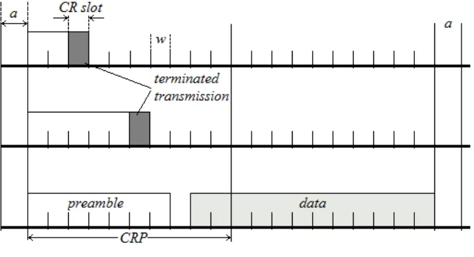
BCSMA/CA, if user, who has packet to send, finds the channel to be idle during the
time period with duration “a” (Figure 1) , then location of Collision Resolution (CR)
distribution specified in the analysis section. CRP stands for collision resolution
period and is a system design parameter since it has to be equal for all stations in the
network. CRP affects channel throughput and there is always an optimal value of CRP
for specific set of system parameters. If the channel is busy then user senses the
channel until it is free for an “a”. Transmission always begins with a preamble (not
useful data) that has a variable length depending on CR slot location. Preamble is
transmitted until the CR slot where user stops and evaluates channel conditions
(listens to channel). If foreign transmissions have been detected then user refrains
from further participation in order to release the channel for others and expects it to be
idle again for a duration of “a”. User is allowed to start data transmission if no
channel activity has been found during the CR slot. For the system to be functional
duration of CR slot denoted in Figure 1 as “w” has to be less than the time needed to
decide whether the channel is free before originating a new transmission stage (a). If
this condition is not met, then user that is about to join the channel and performs
initial carrier sensing will not be able to detect the user that is currently on a CR stage
channel listening, thereby causing a collision. The same consideration was made in
[3].
Behaviour of the described protocol can be referred to as 1-persistent type since
devices are given channel access as soon as they sense it is idle for a certain amount
of time. Thus, having two or more users awaiting current transmission to be over,
technically leads to a collision that ideally will be resolved. Figure 1 shows successful
collision resolving for three users. From the figure it follows that User 1 stops first
and detects Users 2 and 3. Therefore, he terminates the transmission as well as User 2
terminates his transmission because User 3 is active. Consequently, User 3 has
transmission. However, it is important to understand that successful collision
resolving in BCSMA/CA is not always guaranteed. Scenario where collision
resolving mechanism fails is depicted in Figure 2. Here User 1 successfully detects
other users and aborts his transmission whereas User 2 and 3 are not able to detect
each other since they have chosen the same CR slot therefore thinking that medium is
free. As a result both of them start using the channel causing a collision that can now
be resolved only on higher levels. Thus, in case where two or more users have chosen
[image:13.595.153.494.295.480.2]the same largest (among all chosen) CR slot is not resolvable.
[image:13.595.150.497.437.697.2]Fig. 1. Successful collision resolving
Fig. 2. Failure of collision resolving
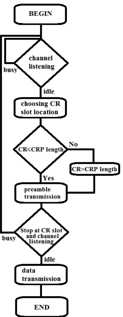
Figure 3 summarizes this section and shows the block-diagram of simplified operation
CR slot is greater than the length of CRP is explained in the following sections and
[image:14.595.238.444.156.685.2]depends on the method by which the CR slot is chosen randomly.
3. Throughput Analysis
Model description: In the analysis it is assumed that the medium is slotted after it
has been sensed idle for time a and users can start their transmission only at slot
boundaries – even weaker assumption of slotted medium than made in [3]. As was
mentioned in the previous section w denotes the duration of the time slot. In this case
it is easier to treat the time in terms of time slots. Thus, R and L denote the length of
CRP and data packet in time slots respectively. For the purpose of simplification L is
a fixed system parameter and channel is assumed to be idle providing error-free
packet reception for N users with no hidden or exposed nodes. Without loss of
generality L/w can be assumed to be an integer. The system is analysed under
saturation condition meaning that each user always has a packet to send. Thus, this
section provides throughput analysis for saturation mode which is defined in [12] as
fundamental performance figure that shows the limit of system throughput with
increasing of offered load. In other words, saturation throughput represents the
maximum load the network can handle in stable conditions.
Throughput analysis: According to the definition, normalized throughput is a
fraction of time the channel is used for useful transmission (data being transmitted)
and therefore can be expressed as:
(1 )
(1 )
mr
s mr c mr
L P
T P T P
η
= −− +
(1)
where Pmr is a probability that collision will not be resolved. Ts denotes time that
passes in case of successful transmission whereas Tc is time that the channel wastes
when collision occurs. The complementary probability of Pmr is the probability that
are less than k except one user that picks the k-th slot. Thus, for given R and N this
complementary probability is
1
1
1
mr R( ) P
N(
1)
k
P
Np k
−k
=
−
=
∑
−
(2)where p(i) is a Probability Mass Function (PMF) and P(i) is a Cumulative
Distribution Function (CDF) of random variable (RV) k that means selected by the
user slot number. Expressions for Ts and Tc are system dependent and always
functions of RV rmax which represents the largest chosen slot number. Probability of
the i-th slot to be the largest or, in other words, PMF of rmax is:
max max
1
( )
Pr(
)
( )
(
1),
[1, ]
N
N j N j
r j
j
p
i
r
i
C p i P
−i
i
R
=
=
= =
∑
−
∈
(3)where N
j
C is the number of combination of N taken j at a time. The fact that (1) now
is also a function of rmax leads to an expression for averaged saturation throughput of
BCSMA/CA: max max 1
[ (
)]
( )
( )
R r iE
r
i p
i
η
η
η
=
=
=
∑
(4)that can be determined for the given R, L, N, Ts, Tc and an arbitrarily chosen
distribution of k. The rest of the section specifies two different distributions – uniform
and exponential and gives all required derivations in order to obtain the saturation
throughput using expression (4).
A) Uniform distribution
For uniform distribution, the probability of choosing any time slot within the CRP
is the same and equal to 1/R. Thus, the PMF and CDF of uniformly distributed RV k
are given by:
1 , [1, ]
( ) R i R
p i
∈
0, 0
( ) , 0
1, i i
P i i R
R
i R ≤
= < ≤
>
(6)
Substituting (5) and (6) into (2) and solving for Pmr using standard algebra gives:
1 1
1
(
1)
NN R mr i
N
P
i
R
− == −
∑
−
(7)Substituting (5) and (6) into (3) results in:
max
1
1
1
( )
,
[1, ]
j N j N
N
r j
j
i
p
i
C
i
R
R
R
− =−
=
∈
∑
(8)Thus, using equations (1), (7), (8) and (4) a closed-form expression for saturation
throughput given R and N can be found.
1 1
1
1
(
N)
j N j
R N N j j s c
LNS
C
T NS
T R
NS
R
R
ξ
ξ
η
− = =−
=
+
−
∑
∑
(9)Here 1
1
( 1)N
N R i N S i R − =
=
∑
− and both Ts = Ts(ξ), Tc = Tc(ξ).B) Exponential distribution
Due to continuous nature of exponential distribution it is impossible to implement it
directly. For this purpose we use a quantization technique where each number if it is
smaller than R-1 is assigned to the nearest larger integer or to the R otherwise. Thus,
PMF is given by:
1
( ) Pr( ) , [1, 1]
i
x
i
p i k i
λ
e−λ dx i R −= = =
∫
∈ − (10)or (if the number exceeds R-1)
1 1
( ) Pr( ) x 1 R
R
p R k R
λ
e λ dx p∞ −
− −
Consequently the CDF is:
( ) Pr( ) Pr( ) k, [1, ]
i k i
P i k i k p i R
γ
γ
≤ ≤
= ≤ =
∑
= =∑
∈ (12)Here λ is the parameter of exponential distribution (λ-1 is the mean value) and has to
be defined along with other parameters as R, L, N, Ts, Tc. We notice again that Ts and
Tc are functions of RV rmax and therefore not constants. Thus, substituting (10), (11),
(12) into (2) and (3) and then using (4) together with (1), saturation throughput of
BCSMA/CA in case of exponential distribution can be calculated.
4. Results and Discussion
This section is divided into several parts. Part A gives a comparison of BCSMA/CA
protocol for uniform and exponential distribution and demonstrates the superiority of
the latter. In Part B the effect of different parameter combinations on system
performance are investigated. Next section shows the saturation throughput of
BCSMA/CA and WCSMA/CD for the same set of parameters. Finally, part D
describes the state-of-the-art 802.11 distributed coordination function (DCF) and a
method for embedding BCSMA/CA in it.
A) Comparison of uniform and exponential distribution.
In order to compare the two proposed distributions we show the most important
results of analytical model. Figures 4 and 5 depict probability of unsuccessful
transmission and saturation throughput versus number of users respectively. It is
important to say that propagation delay is negligible here since it is assumed to be
much smaller than slot duration therefore giving values of Ts and Tc as:
Since BCSMA/CA does not distinguish whether transmission is successful or not,
time the channel is spent in collision and successful transmission are equal. The
values of all other parameters that have been used to obtain numerical results are
detailed in Table I.
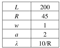
L 200
R 45
w 1
a 2
[image:19.595.263.366.184.266.2]λ 10/R
Table 1. Parameters used to compare uniform and exponential distribution
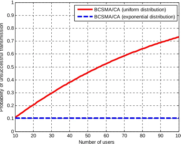
From Figure 4 it follows that probability for the packet to collide in case of uniform
distribution grows rapidly and is over 0.7 for a hundred users whereas the same
probability for exponential distribution grows extremely slowly so that it is even
difficult to notice. This fact can be explained by nature of exponential distribution
where choosing small values is most likely. Thus, any new user does not affect the
system performance significantly since the slot number he chooses is also small and
probably not the largest. For the uniform distribution it is not true. Users here choose
any slot with equal probability and therefore the chosen slot number has much higher
probability to be selected by anybody else and be the largest at the same time. Thus, it
is not a surprise that saturation throughput shown in Figure 5 is so much different for
proposed distributions. The blue dashed line representing the exponential distribution
decays less than 5% over a span of 100 users with approximate throughput of 80%. In
addition, exponential distribution is more flexibility and adaptive due to its parameter
λ that can be adjusted according to environment and needs. For example, by changing
λ for a certain group of users or applications Quality of Service (QoS) can be
provided. Since the superiority of the exponential distribution is obvious, in the rest of
10 20 30 40 50 60 70 80 90 100 0 0.1 0.2 0.3 0.4 0.5 0.6 0.7 0.8 0.9 1
Number of users
P ro b a b il it y o f u n s u c c e s s fu l tr a n s m is s io n
BCSMA/CA (uniform distribution) BCSMA/CA (exponential distribution)
Fig. 4. Probability of unsuccessful transmission for uniform and exponential distribution
10 20 30 40 50 60 70 80 90 100
0.2 0.3 0.4 0.5 0.6 0.7 0.8 0.9 1
Number of users
S a tu ra ti o n t h ro u g h p u t
[image:20.595.161.471.88.334.2]BCSMA/CA (uniform distribution) BCSMA/CA (exponential distribution)
Fig. 5. Saturation throughput for uniform and exponential distribution
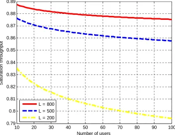
B) Effect of different parameters on system performance
As described in chapter 2, BCSMA/CA introduces variable overhead by using
preamble along with CR slot. Thus, even if collision is resolved successfully the time
Such behaviour is confirmed by numerical results and depicted in Figure 6. Moreover,
advantage of large packet size is also provided by ideal channel conditions since with
error-prone reception probability that a single bit is corrupted and therefore
probability that packet is retransmitted increases with the size of the packet. As in
former section parameter values are summarized in Table 2.
L 800, 500, 200
R 50
w 1
a 2
[image:21.595.254.378.210.289.2]λ 10/R
Table 2. Parameters used to evaluate the effect packet size
10 20 30 40 50 60 70 80 90 100
0.79 0.8 0.81 0.82 0.83 0.84 0.85 0.86 0.87 0.88 0.89
Number of users
S
a
tu
ra
ti
o
n
t
h
ro
u
g
h
p
u
t
L = 800 L = 500 L = 200
Fig. 6. Saturation throughput for different packet sizes
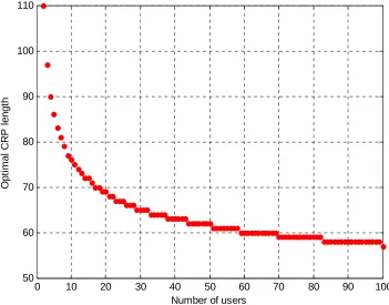
Another critical parameter which affects the system performance is the length of
CRP. On the one hand, a small value of R reduces the overhead introduced by the
protocol which increases the throughput. On the other hand, insufficient CRP length
[image:21.595.138.491.339.611.2]value of R for given number of users is expected. Figure 7 proves this fact and shows
optimal duration of CRP for different number of users.
0 10 20 30 40 50 60 70 80 90 100
50 60 70 80 90 100 110
Number of users
O
p
ti
m
a
l
C
R
P
l
e
n
g
[image:22.595.138.489.145.420.2]th
Fig. 7. Optimal CRP length for different number of users
However, using optimal CRP value is not practical. This information must be
somehow distributed among the users in the network which is not an easy goal to
achieve since the number of users in the network frequently changes. For that reason
Figure 8 gives the channel throughput for optimal and fixed length of CRP. Relying
on the previous figure, R value has been chosen to be close to the optimal value for
large N. This choice explains the fact that sub-optimal curve is below the optimal one
only when number of users is relatively small and matches it otherwise. Thus, using
fixed CRP length does not affect the system throughput significantly, especially for
0 10 20 30 40 50 60 70 80 90 100 0.86
0.87 0.88 0.89 0.9 0.91 0.92 0.93
Number of users
S
a
tu
ra
ti
o
n
t
h
ro
u
g
h
p
u
t
[image:23.595.136.489.88.364.2]Optimal CRP CRP = 58
Fig. 8. Saturation throughput for optimal and sub-optimal CRP values
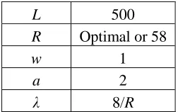
Parameters used to obtain two previous figures are given in Table 3.
L 500
R Optimal or 58
w 1
a 2
λ 8/R
Table 3. Parameters used to evaluate the effect of CRP length
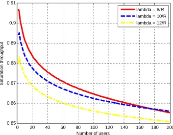
Parameter of exponential distribution λ also has an effect on saturation throughput.
For simplicity, we assume that it is a function of CRP length (i.e. λ = λ(R)). Since in
real system design CRP does not change Figure 9 investigates how λ influence the
system performance in terms of throughput for a fixed sub-optimal value of R taken
from Table 3. All other parameters also remained their values. Note that in figure 9,
[image:23.595.253.379.426.505.2]0 20 40 60 80 100 120 140 160 180 200 0.85
0.86 0.87 0.88 0.89 0.9 0.91
Number of users
S
a
tu
ra
ti
o
n
t
h
ro
u
g
h
p
u
t
[image:24.595.137.490.88.364.2]lambda = 8/R lambda = 10/R lambda = 12/R
Fig. 9. Saturation throughput for different values of lambda
From the figure it follows that choice of λ can vary depending on the number of
users expected. For example, if N lies in the range of 1 and 170 then it is better to use
λ = 8/R. In the case when N is larger than 180 utilizing λ = 10/R appears to be more
preferable.
The next parameter examined in this section is the slot duration w. It is important to
remember that slot duration and time required for sensing the channel idle before
initiating a new transmission are related to each other. Thus, figure 10 shows the
channel throughput for different combinations of w and a while keeping the same
values of other parameters (Table 3). Presented results are intuitive since increasing
values of w and a results in increased overhead and therefore lower values of
saturation throughput. Note that slot duration is not a characteristic of the MAC layer.
It is defined by physical layer and comprised of RX-to-TX and TX-to-RX turnaround
0 10 20 30 40 50 60 70 80 90 100 0.75
0.8 0.85 0.9 0.95 1
Number of users
S
a
tu
ra
ti
o
n
t
h
ro
u
g
h
p
u
t
[image:25.595.137.485.90.361.2]w=1, a=2 w=2, a=4 w=3, a=6
Fig. 10. Saturation throughput for different combinations of w and a
It is also interesting to investigate the effect of the number of users on the system.
From figure 4 it follows that probability for a single packet to collide is constant
within the specified range. Consequently, the question why does the channel
throughput go down arises. Figure 11 clarifies that and shows the distribution of RV
rmax given by (3). It can be seen from the figure that for larger N distribution moves to
the right meaning that greater value of CR slot is most likely to be the largest among
all chosen. This fact increases the average time of preamble and therefore explains
throughput degradation. Table 4 reports the parameters used to obtain the results for
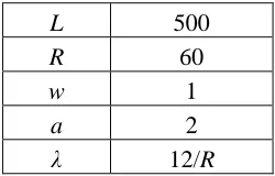
this part.
L 500
R 60
w 1
a 2
λ 12/R
[image:25.595.253.378.656.736.2]0 10 20 30 40 50 60 0
0.01 0.02 0.03 0.04 0.05 0.06 0.07 0.08
CR slot number
P
ro
b
a
b
il
it
y
N=10 N=100
Fig. 11. Probability for the specific CR slot to be the largest for different number of users
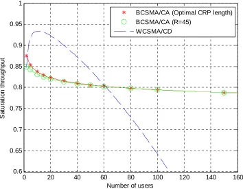
C) Comparison of BCSMA/CA and WCSMA/CD
Some additional assumptions and changes have been made in BCSMA/CA in order
to accurately compare it with WCSMA/CD. Medium now is synchronised in terms of
time slots a and values of L/a and a/w are assumed to be integers. As in section A
propagation delay is neglected and values of Ts and Tc are given by the same
expression (12). Saturation throughput of both protocols is shown in figure 12 for the
same set of parameters as in [11]. Figure 12 also presents curves for optimal and
suboptimal CRP values in case of BCSMA/CA, whereas similar parameter named
CDP in WCSMA/CD is always optimal. It can be noticed that for the given
parameters extra time of w is wasted in every packet transmission when the largest
CR slot is not even. However, in order to make the comparison with [11] fair, neither
analysis nor simulation reflect this fact since [11] includes w into the packet length
figure this statement is valid for the curve with optimal as well as suboptimal fixed
CRP value since they are very close to each other.
0 20 40 60 80 100 120 140 160
0.6 0.65 0.7 0.75 0.8 0.85 0.9 0.95 1
Number of users
S
a
tu
ra
ti
o
n
t
h
ro
u
g
h
p
u
t
BCSMA/CA (Optimal CRP length) BCSMA/CA (R=45)
[image:27.595.132.486.145.420.2]WCSMA/CD
Fig. 12. Comparison of saturation throughput for BCSMA/CA and WCSMA/CD
(a = 2, w = 1, L = 200, λ = 10/R, p = 0.03)
D) Performance of 802.11 DCF under BCSMA/CA
We begin by briefly describing the 802.11 DCF [6] and then discuss how it can
benefit from the proposed protocol. Every station starts evaluating the channel
immediately after it gets a new packet from higher levels. If the channel is sensed idle
for a period of time called distributed interframe space (DIFS), the station is allowed
to transmit. Otherwise, it keeps sensing until medium is free for the DIFS and after
that generates an additional backoff interval according to BEB in order to minimize
the probability of collision. It is important that after the DIFS station treats the
channel in terms of time slots and therefore can transmit only at slot boundaries. BEB
implies that backoff interval (which is now discrete) is uniformly distributed in the
many times the transmission of this packet failed. After the certain number of
unsuccessful retransmissions called retransmission limit packet is discarded. The
station decrements backoff time counter for each idle time slot and transmits only
when it reaches zero. 802.11 DCF assumes that transmission is successful if sender
receives and acknowledgement (ACK) that is transmitted by the receiver as soon as
the packet is received correctly. The time between the RX packet reception and start
of ACK transmission is called short interframe space (SIFS).
Along with the described technique named Basic access method, DCF also defines
an optional mechanism known as RTS/CTS access method. This method follows the
same rules above with an exception that station instead of data packet transmits
special frame called request to send (RTS). Right after receiving the RTS and SIFS
time recipient responds with a clear to send (CTS) frame. Requesting station is
allowed to transmit only when it correctly receives the CTS message. RTS/CTS
technique is used to deal with a hidden nodes problem as well as large number of
users in the network. Operation of both Basic and RTS/CTS access method are
[image:28.595.131.521.525.664.2]depicted in figures 13 and 14 respectively.
Fig. 14. Operation of 802.11 DCF (RTS/CTS access method) [6]
Proposed protocol can successfully replace binary exponential backoff scheme
implemented in IEEE 802.11 DCF for collision avoidance. In this case a refers to the
DIFS time, L refers to the payload size and w to the slot duration. Figure 15 shows the
comparison of saturation throughput of original DCF obtained by analytical model
from [13] and DCF with embedded BCSMA/CA. Due to extra time required for
preamble transmission Ts and Tc are larger by wrmax than those in [13] and now equal
to:
max
max bas
s
bas c
T wr H L SIFS ACK DIFS
T wr H L SIFS ACK DIFS
δ δ
δ δ
= + + + + + + +
= + + + + + + +
(13)
max
max rts
s
rts c
T wr RTS SIFS CTS SIFS
H L SIFS ACK DIFS
T wr RTS SIFS CTS DIFS
δ δ
δ δ
δ δ
= + + + + + +
+ + + + + + +
= + + + + + +
(14)
for the Basic and RTS/CTS methods respectively. H here denotes a total packet
header (H = PHYhdr + MAChdr) and δ is a propagation time. To be consistent with [13]
we use the same payload size and parameters therefore following IEEE 802.11
standard [6] for DSSS with an exception for retransmission limit that is assumed to be
practical, results are given for R = 65 in case of basic method and R = 20 when
RTS/CTS method is used. The values of the parameters used to obtain numerical
results for analytical model as well as for simulation are detailed in Table 5. Since the
curve for basic method of original DCF depicted in figure 15 lies relatively low, the
difference between the rest of the curves is not apparent. For this purpose, figure 16
shows the result in expanded scale for axis y not including aforementioned curve.
Observation of figure 16 shows that DCF under BCSMA/CA is significantly more
efficient and preferable to use when the number of users is large. All analytical results
presented in this section and section D are validated through simulation performed in
Matlab. Simulation results are superimposed over the analytical curves using marker
points.
Packet payload 8224 bits
MAC header 224 bits
PHY header 192 bits
ACK 112 + PHY header
RTS 160 + PHY header
CTS 112 + PHY header
Channel bit rate 1 Mbit/s
Propagation delay 1 µs
Slot time 20 µs
SIFS 10 µs
[image:30.595.206.425.400.589.2]DIFS 50 µs
Table 4. 802.11 DSSS system parameters and additional
0 50 100 150 200 250 300 0.2 0.3 0.4 0.5 0.6 0.7 0.8 0.9 1
Number of users
S a tu ra ti o n t h ro u g h p u t
DCF (BCSMACA) Basic DCF (BCSMACA) RTS/CTS DCF (BEB) Basic
[image:31.595.143.479.87.352.2]DCF (BEB) RTS/CTS
Fig. 15. Evaluation of saturation throughput for traditional and modified DCF
( CRPBasic = 65, CRPRTS/CTS = 20, λ = 10/CRP )
0 50 100 150 200 250 300
0.75 0.76 0.77 0.78 0.79 0.8 0.81 0.82 0.83 0.84
Number of users
S a tu ra ti o n t h ro u g h p u t
DCF (BCSMACA) Basic DCF (BCSMACA) RTS/CTS DCF (BEB) RTS/CTS
Fig. 16. Evaluation of saturation throughput for traditional and modified DCF (expanded scale)
[image:31.595.140.478.426.694.2]5. Conclusion
In this thesis we proposed a novel random channel access protocol for wireless
networks named BCSMA/CA. Each user in BCSMA/CA is given the channel access
right after the medium is sensed idle for a certain amount of time. However,
transmission starts with preamble (instead of data) by which users can detect each
other and therefore avoid collisions. With the help of analytical model that assumes
ideal channel conditions, fixed packet size and finite number of users, the effect of
different parameters on BCSMA/CA performance was investigated. We gave
recommendations for choosing specific parameters’ values and showed that using
fixed suboptimal value of contention resolution period has marginal impact on
saturation throughput. This work also includes the comparison of WCSMA/CD
described in [11] and BCSMA/CA for the same set of parameters. Comparison
showed the rapidly growing positive difference between saturation throughput of the
proposed protocol and WCSMA/CD as the number of users increases. Being
implemented into the IEEE 802.11 DCF instead of BEB, BCSMA/CA was also
compared to the original DCF and proved to have an advantage for large number of
users. Even though, proposed protocol gives promising results in highly populated
wireless networks, certain parameters as λ and quantization technique might be
non-optimal. Thus, optimization of these parameters as well as study of delay and fairness
6. Bibliography
[1] N. Abramson, “The Aloha System – Another Alternative for Computer Communications”,
Proc. AFIPS Fall Joint Computer Conf., 1970.
[2] R.M. Metcalf and D.R. Boggs, “Ethernet: Distributed Packet Switching for Local Computer Networks”, Comm. ACM, vol. 19, pp. 395-404, July 1976.
[3] R. Rom, “Collision Detection in Radio channels”, in Local Area and Multiple Access
Networks, Computer Science Press, 1986.
[4] Douglas S. Chan and Toby Berger, “Collision Detection for Carrier Sense Multiple Access”, IEEE 16th international Symposium on Personal, Indoor and Mobile Radio
Communications, 2005.
[5] Jun Peng, Liang Cheng, Biplab Sikdar, “A wireless MAC Protocol with Collision Detection”, IEEE Transactions on mobile computing, vol. 6, NO. 12, December 2007
[6] Wireless LAN Medum Access Control (MAC) and Physical Layer (PHY) Specifications, IEEE Std. 802.11, IEEE Computer Society, 1999.
[7] Khalid M.J. Khayat, Fayez Gebali, Esam Abdel-Raheem, “Performance Analysis of the IEEE 802.11 DCF”, IEEE International Symposium on Signal processing and Information
Technology, 2007.
[8] Jianli Zhang, Zhiyi Fang, Yunlong Zhang, Yongbo Ma, “ZDCF: An improvement DCF Solution of IEEE 802.11”, IEEE international Symposium on Parallel and Distributed
Processing with Applications, 2009.
[9] J. Lee, I. Yeom, “Avoiding Collisions with Hidden Nodes in IEEE 802.11 Wireless Networks”, IEEE Communications letters, vol. 13, NO. 10, October 2009
[10] J. Choi, J. Yoo, S. Choi, C. Kim, “EBA: An Enhancement of the IEEE 802.11 DCF via Distributed Reservation”, IEEE Transactions on mobile computing, vol. 4, NO. 4, July/August
2005
[11] K. Voulgaris, A. Gkelias, I. Ashraf, M. Dohler, A. H. Aghvami, "Throughput Analysis of Wireless CSMA/CD for a finite user population," IEEE Vehicular Technology Conference
(VTC2006-Fall), Montreal, Canada, Sept. 2006.
[12] G. Bianchi, “Performance Analysis of the 802.11 Distributed Coordination Function”,
IEEE Journal on selected areas in communications, vol. 18, NO. 3, March 2000