Web crippling strength of cold-formed stainless steel lipped
channels with web perforations under end-two-flange loading
Amir M. Yousefi1, Asraf Uzzaman2, James B.P. Lim1, G. Charles Clifton1,
Ben Young3
1Department of Civil and Environmental Engineering, The University of Auckland, New Zealand 2Department of Mechanical and Aerospace Engineering, The University of Strathclyde, 75 Montrose
Street, Glasgow G1 1XJ, UK
3Department of Civil Engineering, The University of Hong Kong, Pokfulam Road, Hong Kong
(Received: ; Revised: ; Accepted: )
Abstract: This paper presents a finite element investigation into the web crippling strength of cold-formed stainless steel lipped channels with circular web perforations under end-two-flange (ETF) loading. The cases of web openings located both centred and offset to the load bearing plates, are considered. In order to take into account the influence of the circular web openings, a parametric study involving 2,190 finite element analyses was performed, covering duplex EN1.4462, austenitic EN1.4404 and ferretic EN1.4003 stainless steel grades; from the results of the parametric study, strength reduction factor equations are determined. The strength reduction factor equations are first compared to equations recently proposed for cold-formed carbon steel lipped channels. It is demonstrated that the strength reduction factor equations proposed for cold-formed carbon steel are conservative for the stainless steel grades by up to 10%. New coefficients for web crippling strength reduction factor equations are then proposed that can be applied to all three stainless steel grades.
Nomenclature
A Web opening ratio;
a Diameter of circular web opening;
bf Overall flange width of section;
bl Overall lip width of section;
COV Coefficient of variation;
d Overall web depth of section;
E Young’s modulus of elasticity;
h Depth of the flat portion of web;
L Length of the specimen;
N Length of the bearing plate;
PASCE Nominal web crippling strength obtained from American Code;
PAS/NZS Nominal web crippling strength obtained from Australian/New Zealand Code;
PFEA Web crippling strength per web predicted from finite element (FEA);
PBS Nominal web crippling strength obtained from British Code;
PEuro Nominal web crippling strength obtained from Euro Code;
Pm Mean value of analysed-to-predicted load ratio;
R Reduction factor;
RP Proposed reduction factor;
ri Inside corner radius of section;
Angle between web and bearing surface
t Thickness of section;
VP Coefficient of variation of Analysed-to-predicted load ratio;
x Horizontal clear distance of the web openings to the near edge of the bearing plate;
1 Introduction
Cold-formed stainless steel sections are most often used for both architectural and
structural applications in conditions characterised by high corrosion aggressiveness; not only
because they are aesthetically pleasing, but they also have favourable characteristics in
terms of strength, durability and formability (Zhao et al. 2016; Nethercot et. al. 2011; Rosi
et al. 2009). To provide ease of access for services, the use of web openings for such sections
are also becoming popular in industry (Lawson et al. 2015) (see Fig. 1). Such web openings,
however, result in the sections being more susceptible to web crippling, especially under
concentrated loads in the vicinity of the openings.
The authors have recently proposed unified strength reduction factor equations for the
web crippling strength of cold-formed stainless steel lipped channel-sections with circular
web openings under the one and two flange loading conditions (Yousefi et al. 2016a, b, c, d).
The equations covered three stainless steel grades: duplex grade EN 1.4462; austenitic grade
EN 1.4404 and ferritic grade EN 1.4003. Similar equations for cold-formed carbon steel under
end-one-flange loading condition have previously been proposed by Lian et al. (2016a, b),
which was a continuation of the work of Uzzaman et al. (2012a, b, c, 2013) who had
considered the two-flange loading conditions. When applied to the stainless steel grades,
Yousefi et al. (2016b) showed that the equations proposed by Lian et al. (2016b) for the
end-one-flange (EOF) loading condition were unconservative by up to 7%. Also, Yousefi et al.
(2016d) showed that the equations proposed by Uzzaman et al. (2012a, c) for the
interior-two-flange (ITF) loading condition were unconservative by up to 17%.
In the literature, for cold-formed stainless steel lipped channel-sections, only Krovink
et al. (1995) has considered web crippling strength, but limited to sections without openings.
Zhou and Young (2006, 2007, 2008, 2013) have considered the web crippling strength of
al. (2015), while concerned with circular web openings, focussed on the bending strength of
the sections and not on the web crippling strength under concentrated loads (see Fig. 1).
In terms of cold-formed carbon steel, Keerthan and Mahendran (2012) and Keerthan et
al. (2014) considered the web crippling strength of hollow flange channel beams, again
without openings. Sundararajah et al. (2016) and Gunalan and Mahendran (2015) have also
considered a Direct Strength Method approach for the web crippling strength of channel
sections, again without openings. For cold-formed carbon steel lipped channel-sections, recent
work has included Natario et al. (2014); Chen et al. (2015) and Gunalan and Mahendran
(2015), all without openings.
This paper considers the case of the web crippling strength of cold-formed stainless steel
lipped channels with circular web perforations under the end-two-flange (ETF) loading
condition (see Figs. 2 and 3), and applicability of the proposed equations by Uzzaman et al.
(2012c, 2013) to the same three stainless steel grades, namely the duplex grade EN 1.4462;
austenitic grade 1.4404 and ferritic grade 1.4003. Similar to previous investigations, typical
stress-strain curves for the three grades were taken from Chen and Young (2006) and
Arrayago et. al. (2015).
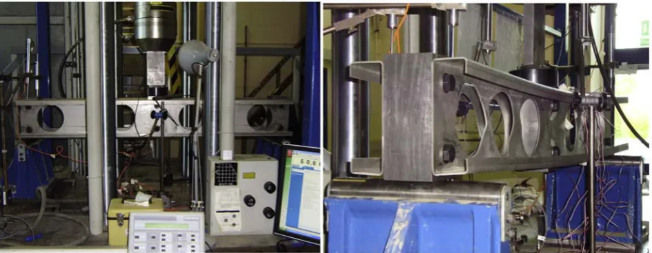
2 Experimental Investigation
For cold-formed carbon steel, Uzzaman et al. (2012b, 2013) conducted 100
end-two-flange (ETF) laboratory tests on lipped channel-sections with circular web openings subjected
to web crippling (see Fig. 3). The size of the circular web openings was varied in order to
investigate the effect of the web openings on the web crippling strength. All the test specimens
were fabricated with web openings located at the mid-depth of the webs with centred and
offset to the bearing plates. The laboratory test results were used to validate a non-linear
et al. (2012b, 2013)), which was then used for a parametric study to investigate the web
crippling strength of cold-formed stainless steel lipped channel-sections with circular web
openings under the end-two-flange (ETF) loading condition. Recommendations were
proposed in the form of strength reduction factor equations, relating the loss of strength due
to the web openings to the strength of the web without openings. The size of the circular web
openings was varied in order to investigate the effect of the web opening size on the web
crippling strength. Full details of both the laboratory tests can be found in Uzzaman et al.
(2012b, 2013).
3 Numerical Investigation
3.1 General
In this study, the non-linear elasto-plastic general purpose finite element program
ABAQUS (2014) was used to simulate the cold-formed stainless steel lipped channels with
and without circular web perforations subjected to web crippling. The bearing plates, the
lipped channel-section with circular web perforations and the interfaces between the bearing
plates and the lipped-channel section were modelled. In the finite element model, the model
was based on the centreline dimensions of the cross-sections. Details of the finite element
models in ABAQUS (2014) are summarised below.
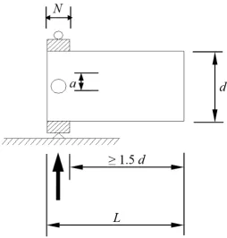
3.2 Specimens labelling
The dimensions of the lipped channel-section modelled are given in Table 1. Fig. 4
shows the definition of the symbols used to describe the dimensions of the cold-formed carbon
steel lipped channel-sections considered in the test programme. The same definitions were
used in this numerical investigation; the models have been coded such the nominal dimension
circular web perforations to the depth of the flat portion of the webs (a/h) can be determined
from the coding system. As an example, the label “142-N100-A0.2-FR” means the following.
The first notation is the nominal depth of the models in millimeters. The notation ''N100''
indicates the length of bearing in millimeters (i.e. 100 mm). The notation ''A0.2'' indicates the
ratio of the diameter of the holes to the depth of the flat portion of the webs (a/h) and are one
of 0.2, 0.4, 0.6 and 0.8 (i.e. A0.2 means a/h = 0.2; A0.4 means a/h = 0.4 etc). Channel-sections
without circular web perforations are denoted by ''A0''. The flanges unfastened and fastened
cases are identified as ''FR'' and ''FX'', respectively.
3.3 Geometry and material properties
In the finite element model, full model of the test set-up of Uzzaman et al. (2012b,
2013) was modelled, as shown in Fig 5. The stress-strain curves for duplex grade EN 1.4462;
austenitic grade 1.4404 and ferritic grade 1.4003 were obtained from Chen and Young (2006)
and Arrayago et al. (2015). The stress-strain curves were converted into true stress- strain
curves as per the equations described in the ABAQUS manual (2014).
3.4 Element type and mesh sensitivity
Fig. 5 shows details of a typical finite element mesh of the channel section and the
bearing plates. The effect of different element sizes in the cross-section of the channel section
was investigated to provide both accurate results and reduced computation time. Finite
element mesh sizes were 5 mm × 5 mm for the cold-formed steel channel sections and 10 mm
× 10 mm for the bearing plates.
Cold-formed steel lipped channels with and without web perforations were modelled using
S4R shell element. The S4R is a four-node double curved thin or thick shell element with
that the S4R element is suitable for complex buckling behaviour. The S4R has six degrees of
freedom per node and provides accurate solutions to most applications. The bearing plates and
load transfer block were modelled using analytical rigid plates and C3D8R element, which is
suitable for three-dimensional modelling of structures with plasticity, stress stiffening, large
deflection, and large strain capabilities. The solid element is defined by eight nodes having
three translational degrees of freedom at each node.
3.5 Loading and boundary conditions
Contact between the bearing plates and the cold-formed stainless steel section was
modelled in ABAQUS using the contact pairs option. The interface between the bearing plates
and the cold-formed stainless steel section were modelled using the surface-to-surface contact
option. The bearing plates were the master surface, while the flange of the cross-section of
stainless steel section was the slave surface extended up to the corners. Since the web-flange
rounded transition will contact the bearing plates due to undergoing heavy deformation, the
contact surfaces must include the corner elements and the flange. The two contact surfaces
were not allowed to penetrate each other. The vertical load applied to the channel sections in
the laboratory tests was modelled using displacement control method; an imposed
displacement is applied to the nodes of the top bearing plate where the vertical load is applied.
The top bearing plate was restrained against all degrees of freedom, except for the translational
degree of freedom in the Y-direction. In the flanges fastened condition, the connector was
used in the region where the flanges connected to the bearing plates. The nodes were prevented
from translating in all degrees of freedom except in the y direction. Cartesian connectors were
used to simulate the bolts instead of physically modelling bolts and holes. “CONN3D2”
connector elements were used to model the in-plane translational stiffness i.e. x- and
(2004a, b) suggestion would be suitable. In the y direction, the nodes were prevented from
translating.
3.6 Verification of finite element model
In order to verify the finite element model, the results of experimental study on lipped
carbon steel channel sections 142×60×13-t1.3-N30 and 202×65×13-t1.4-N120 (flanges
unfastened and fastened to the bearing plates) for the cases of web holes located centred and
offset to the bearing plates under ETF loading condition conducted by Uzzaman et al. (2012b,
2013) (see Fig. 3) were compared to the results obtained from the finite element analyses
(Figs. 6 and 7) using the same material as developed for stainless steel materials in this study.
As can be seen, there is good agreement between the failure loads of the tested specimens and
the finite element results. For cold-formed stainless steel lipped channel-sections, the
numerical failure loads with and without circular web perforations were then determined for
the three stainless steel grades: duplex grade EN 1.4462; austenitic grade 1.4404 and ferritic
grade 1.4003 (see Table 1). These results were compared with the failure loads calculated in
accordance with ASCE 8-02 (2002), BS 5950-5 (1998), Eurocode-3 (2006), NAS (2007) and
AS/NZS 4600 (2005) (see Table 2). The failure loads predicted from the finite element results
are generally similar to the standard codified failure loads of the sections.
4 Parametric study for stainless steel grades
In this study, in order to investigate the effect of circular web perforations on the web
crippling strength of cold-formed stainless steel lipped channels, a total of 2,190 finite element
analyses of lipped channels with various dimensions and thicknesses were considered for the
three stainless steel grades: duplex EN1.4462, austenitic EN1.4404 and ferritic EN1.4003.
The web crippling strength predicted was influenced primarily by the ratio of the circular web
of the web and the location of the web hole as defined by the distance of the web perforation
from the edge of the bearing divided by the flat portion of the web (Uzzaman et al. (2012a,b,c,
2013)). In order to find the effect of a/h, N/h and x/h on the web crippling strength of channel
sections with circular web perforations, parametric studies were carried out considering the
circular web perforations, different bearing plate lengths, the cross-section sizes and location
of the circular web perforations. The cases of both flanges fastened and flanges unfastened to
the bearing plates were considered.
The specimens consisted of three different section sizes, having thicknesses (t) ranging
from 1.23 mm to 6.0 mm and web slenderness (h/t) values ranging from 111.7 to 157.8. The
ratios of the diameter of the circular web perforations (a) to the depth of the flat portion of the
webs (h) were 0.2, 0.4, 0.6 and 0.8. The ratios of the distance of the web perforations (x) to
the depth of the flat portion of the web (h) were 0.2, 0.4 and 0.6. Bearing plates of lengths (N)
equal to 100 mm, 120 mm and 150 mm are considered. For each series of specimens, the web
crippling strengths of the sections without the web perforations were obtained. Thus, the ratio
of the web crippling strengths for sections with web perforations divided by the sections
without web perforations, which is the strength reduction factor (R), was used to quantify the
degrading influence of the web perforations on the web crippling strengths.
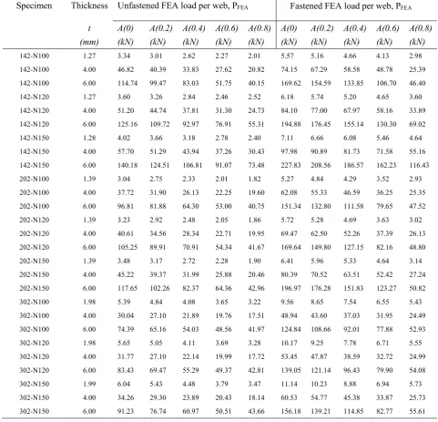
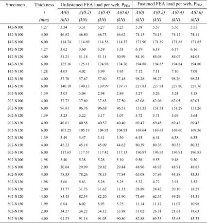
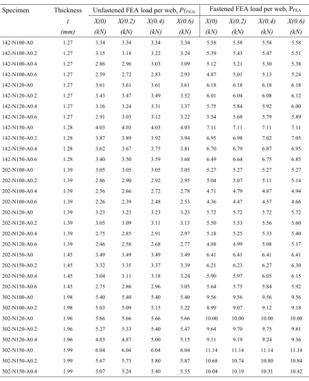
The parametric study investigated the effect of the ratios of a/h, N/h and x/h. The web
crippling strengths (PFEA) per web predicted from the FEA are summarised in Tables 3 to 5
for the duplex grade EN 1.4462. As can be seen from Tables 3 to 5, the failure load of the
cold-formed stainless steel sections reduces as web perforations are present and continues to
reduce with increase in the size of web perforations. The results demonstrate that the failure
load obtained from the cold-formed stainless steel sections with the case of flanges fastened
to bearing plates is in average 25% higher than the case of flanges unfastened to bearing plates
perforations with a horizontal clear distance to the near edge of the bearing plates, the web
crippling strength of the sections is higher than the case of web holes located centred above
the bearing plates. Moreover, for the same section with different span and bearing plates, the
failure loads were found to be different among the results. Based on the results, it was found
that the failure load increases as the length of the bearing plates increases and as the length of
the sections increases. The effect of the ratios of a/h, N/h and x/h on the reduction factor of
the web crippling strength is shown in Fig. 8 for the C142 specimen.
Fig. 8(a) shows the ratio of the circular web perforation depth to the flat portion of the
web (a/h) versus the strength reduction factor, for the three stainless steel grades. As can be
seen, the reduction in strength increases as the parameter a/h increases for all three stainless
steels, in particular for the ferritic grade with lower thickness (1.3mm). The reduction in
strength of the ferritic grade 6 mm thick section is smallest and the reduction in strength
increases as the section becomes thinner. It can be seen that when the a/h ratioincreases from
0.2 to 0.6, the reduction in strength for the ferritic grade increases by 28%.
Fig. 8(b) shows the ratio of the bearing length to the flat portion of the web (N/h) versus
the strength reduction factor, for the three stainless steel grades. As can be seen, the reduction
in strength is not sensitive to the ratio N/h and the 6 mm thick sections have the smallest
reduction in strength or the highest strength reduction factor.
Fig. 8(c) shows the ratio of the circular web hole location to the flat portion of the web
(x/h) versus the strength reduction factor, for the three stainless steel grades. As can be seen,
the reduction in strength is sensitive to the horizontal distance of the web perforations to the
bearing plates. As the ratio of x/h decreases from 0.6 to 0.2, the strength reduction factor
decreases by 7%. Also, it can again be seen that the reduction in strength is less for the
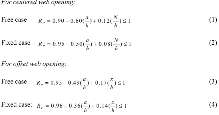
5 Reduction factor comparison with Uzzaman et al. (2012c, 2013)
For ease of reference, the reduction factor equations proposed by Uzzaman et al. (2012c,
2013) are summarised below:
For centered web opening:
Free case RP 0.90 0.60( ) 0.12(a N) 1
h h
(1)
Fixed case P 0.95 0.50( ) 0.08( ) 1
a N
R
h h
(2)
For offset web opening:
Free case RP 0.95 0.49( ) 0.17( ) 1a x
h h
(3)
Fixed case: RP 0.96 0.36( ) 0.14( ) 1a x
h h
(4)
where the limits for the reduction factor in Eqs. (1)-(4) are h t/ 156, N t/ 84,
/ 0.63,
N h a h/ 0.8, and 900.
In order to evaluate the applicability of the proposed equations to cold-formed stainless
[image:11.595.83.467.159.360.2]steel grades, an extensive statistical analysis was performed on all four proposed equations.
Table 6 compares the reduction factors determined from the finite element models to Eqs.
(1)-(4) for cases of centred and offset web perforation where the flanges are unfastened to the
bearing plates.
As can be seen from Table 6, the four equations proposed by Uzzaman et al. (2012c,
2013) for carbon steel are conservative for the stainless steel grades, especially for the ferritic
stainless steel grade which are conservative by up to 10%. As an example, for the ferritic
stainless steel grade, for the centred web perforation case, the mean value of the web crippling
reduction factors are 1.10 and 1.00 for the cases of flanges unfastened and fastened to the
Similar values nearly are reported for the case of the duplex stainless steel grade. In the next
section, new equations are proposed for each of the three stainless steel grades.
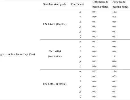
6 Proposed strength reduction factors
Tables 3 to 5 show the dimensions considered and web crippling strengths of the
stainless steel sections predicted from the finite element analysis. Using bivariate linear
regression analysis, two unified strength reduction factor equations (Rp) for three stainless
steel grades with web openings are proposed. The equations are as follows:
Centred web opening: Rp ( )a ( ) 1N (5)
h h
Offset web opening: Rp ( )a ( ) 1x (6)
h h
The limits for the reduction factor Eqs. (5)-(6) are h t/ 157.68, N t/ 120.97, N h/ 1.15,
/ 0.8
a h , and 90 .0 The coefficientsα, γ, λ, ρ, μ andζof the equations are calibrated
with the stainless steel finite element analysis results, and the coefficients are presented in
Table 7.
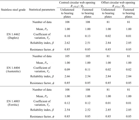
7 Comparison of numerical results with proposed reduction factors
For the three stainless steels grades, the values of the strength reduction factor (R)
obtained from the numerical results are compared with the values of the proposed strength
reduction factor (Rp) calculated using Eqs. (5) and (6). The results for C142, C202 and C302
are shown in Figs. 9 to 12. In order to evaluate the accuracy of proposed equations, extensive
statistical reliability analyses are performed. The results are summarized in Table 8. It should
be noted, in calculating the reliability index, the resistance factor of was used,
corresponding to the reliability index β from the North American Specification (NAS, 2007).
reliability analysis, where DL is the dead load and LL is the live load. In this study, Mm= 1.10
and VM= 0.10, which are the mean and coefficients of variation for the material properties
factors, Fm= 1.00 and VF= 0.05, which are the mean and coefficients of variation for the
fabrication factors, and Vq= 0.21, which is the coefficient of variation of load effect were used.
According to the NAS specification, design rules are reliable if the reliability index is more
than 2.5. As can be seen in Table 8, the proposed reduction factors are a good match with the
numerical results for the both cases of flanges unfastened and flanges fastened to the bearing
plates.
For example, for the centred circular web perforation, the mean value of the web
crippling reduction factor ratios are 1.00 and 1.00 for the cases of flanges unfastened and
flanges fastened to the bearing plates, respectively. The corresponding values of COV are 0.10
and 0.13, respectively. Similarly, the reliability index values (β) are 2.62 and 2.51,
respectively. For the offset circular web perforation, the mean value of the web crippling
reduction factor ratios are 1.00 and 1.00 for the cases of flanges unfastened and flanges
fastened to the bearing plates, respectively. The corresponding values of COV are 0.02 and
0.01, respectively. Similarly, the reliability index values (β) are 2.84 and 2.85, respectively.
Therefore, the proposed strength reduction factor equations are able to reliably predict the
influence of the circular web perforations on the web crippling strengths of cold-formed
stainless steel lipped channels under end-two-flange (ETF) loading.
8 Conclusions
In this paper, an investigation into the effect of circular web perforations on the web
crippling strength of cold-formed stainless steel lipped channels has been conducted. For this
purpose, a parametric study comprising 2,190 lipped channels with various dimensions,
austenitic EN1.4404 and ferretic EN1.4003. Cases with and without circular web perforations
under the end-two-flange (ETF) loading were considered with web holeslocated centred and
offset to the bearing plates.
In order to take into account the influence of the circular web perforations, strength
reduction factor equations were determined. The strength reduction factor equations were then
compared to equations proposed by Uzzaman et al. (2012c, 2013) for cold-formed carbon
steel. It was observed that the strength reduction factor equations proposed for cold-formed
carbon steel are conservative for the stainless steel grades by up to 10%.
Based on the finite element results obtained from this study, new coefficients for web
crippling strength reduction factor equations considering different web hole diameter and
location in the web were proposed for both cases of flanges unfastened and flanges fastened
to the bearing plates under end-two-flange (ETF) loading. Reliability analyses were performed
in order to evaluate the reliability of the proposed strength reduction factors. It was
demonstrated that the proposed strength reduction factors are generally conservative and agree
well with the finite element results. The proposed new unified strength reduction factors are
capable to produce reliable and safe yet not too conservative design values when calibrated
Acknowledgement
The University of Auckland Doctoral Scholarship is greatly acknowledged.
Declaration of Conflicting Interests
The author(s) declared no potential conflicts of interest with respect to the research, authorship
and/or publication of this article.
Funding
The author(s) received no financial support for the research, authorship and/or publication of
References
ABAQUS. (2014), Analysis User’s Manual-Version 6.14-2 ABAQUS Inc., USA.
Arrayago, I., E. Real, L. Gardner (2015), "Description of stress–strain curves for stainless steel alloys", Materials & Design, 87, 540-552.
AS/NZS 4600 (2005), Cold-formed steel structures: AS/NZS 4600:2005, Standards Australia, Sydney, Australia.
ASCE 8-02 (2002), Specification for the Design of Cold-Formed Stainless Steel Structural Members: SEI/ASCE 8-02, Reston, VA.
BS 5950-5 (1998), Structural use of steelwork in buildings, Part 5 Code of practice for the design of cold-formed sections. British Standards Institution, London.
Chen, J., and Ben Young (2006), "Stress–strain curves for stainless steel at elevated temperatures", Engineering Structures, 28(2), 229-239.
Chen, Y., Xixiang Chen, Chaoyang Wang (2015), "Experimental and finite element analysis research on cold-formed steel lipped channel beams under web crippling", Thin-Walled Structures, 87, 41-52.
Gunalan, S., M. Mahendran (2015), "Web crippling tests of cold-formed steel channels under two flange load cases", Journal of Constructional Steel Research, 110, 1-15. Eurocode-3 (2006), Design of steel structures: Part 1.3: General rules — Supplementary
rules for cold-formed thin gauge members and sheeting, in: ENV 1993-1-3, European Committee for Standardization, Brussels, Belgium.
Keerthan, P., and Mahen Mahendran (2012), "Shear behaviour and strength of LiteSteel beams with web openings", Advances in Structural Engineering, 15(2), 171-184. Keerthan, P., Mahen Mahendran, Edward Steau (2014), "Experimental study of web
crippling behaviour of hollow flange channel beams under two flange load cases",
Thin-Walled Structures, 85, 207-219.
Korvink, S.A., G.J. van den Berg, P. van der Merwe (1995), "Web crippling of stainless steel cold-formed beams", Journal of Constructional Steel Research, 34 (2-3), 225-248.
Lian, Y., Uzzaman A., Lim J.B.P., Abdelal G., Nash D., Young B. (2016a), "Effect of web holes on web crippling strength of cold-formed steel channel sections under end-one-flange loading condition - Part I: Tests and finite element analysis", Thin-Walled Structures, 107, 443-452
Lian, Y., Uzzaman A., Lim J.B.P., Abdelal G., Nash D., Young B. (2016b), "Effect of web holes on web crippling strength of cold-formed steel channel sections under end-one-flange loading condition - Part II: Parametric study and proposed design equations",
Thin-Walled Structures, 107, 489-501.
Lim, J.B.P., and Nethercot, D.A. (2004a). "Finite element idealisation of a cold-formed steel portal frame", Journal of Structural Engineering, 130:1, pp.78-94.
Lim, J.B.P., and Nethercot, D.A. (2004b). "Stiffness prediction for bolted moment-connections between cold-formed steel members", Journal of Constructional Steel Research, 60:1, pp.85-107.
NAS (2007), North American Specification for the Design of Cold-Formed Steel Structural Members: American Iron and Steel Institute, AISI S100-2007, AISI Standard. Natário, P., N. Silvestre, D. Camotim (2014), "Web crippling failure using quasi-static FE
models", Thin-Walled Structures, 84, 34-49.
Nethercot, D. A., Salih, E. L. and Gardner, L. (2011). "Behaviour and design of stainless steel bolted connections", Advances in Structural Engineering, Vol. 14, No. 4, pp. 647-658. Rossi, B., Jaspart, J. P., & Rasmussen, K. J. (2009), Combined distortional and overall
flexural-torsional buckling of cold-formed stainless steel sections: design. Journal of structural engineering, 136(4), 361-369.
Sundararajah, L., Mahendran, M., Keerthan, P. (2016). Experimental Studies of Lipped Channel Beams Subject to Web Crippling under Two-Flange Load Cases. Journal of Structural Engineering, 04016058.
Uzzaman, A., James B.P. Lim, David Nash, Jim Rhodes, Ben Young (2012a), "Web crippling behaviour of cold-formed steel channel sections with offset web holes subjected to interior-two-flange loading", Thin-Walled Structures, 50, 76-86.
Uzzaman, A., James B.P. Lim, David Nash, Jim Rhodes, Ben Young (2012b), "Cold-formed steel sections with web openings subjected to web crippling under two-flange
loading conditions-part I: Tests and finite element analysis", Thin-Walled Structures,
Uzzaman, A., James B.P. Lim, David Nash, Jim Rhodes, Ben Young (2012c), "Cold-formed steel sections with web openings subjected to web crippling under two-flange
loading conditions-part II: Parametric study and proposed design equations", Thin-Walled Structures, 56, 79-87.
Uzzaman, A., James B.P. Lim, David Nash, Jim Rhodes, Ben Young (2013), "Effect of offset web holes on web crippling strength of cold-formed steel channel sections under end-two-flange loading condition", Thin-Walled Structures, 65, 34-48.
Yousefi, A. M., James B.P. Lim, Asraf Uzzaman, Ying Lian,G. Charles Clifton, Ben Young (2016a), "Web crippling strength of cold-formed stainless steel lipped channel-sections with web openings subjected to Interior-One-Flange loading condition", Steel and Composite Structures,21 (3), 629-659.
Yousefi, A. M., James B.P. Lim, Asraf Uzzaman, Ying Lian,G. Charles Clifton, Ben Young (2016b), "Design of cold-formed stainless steel lipped channel-sections with web openings subjected to web crippling under End-One-Flange loading condition", Advances in Structural Engineering,20(11), 1-22.
Yousefi, A. M., James B.P. Lim, Asraf Uzzaman, Ying Lian,G. Charles Clifton, Ben Young (2016c), "Web Crippling Strength of Cold-Formed Duplex Stainless Steel Lipped Channel-Sections with Web Openings Subjected to Interior-One-Flange Loading Condition", Proceeding of TheWei-Wen Yu International Specialty Conference on Cold-Formed Steel Structures, Baltimore, Maryland, USA.
Yousefi, A. M., Asraf Uzzaman , James B.P. Lim, G. Charles Clifton, Ben Young (2016d), "Numerical investigation of web crippling strength in cold-formed stainless steel lipped channels with web openings subjected to interior-two-flange loading condition", Steel and Composite Structures, revised.
Zhao, O., Leroy Gardner, Ben Young, (2016), Buckling of ferritic stainless steel members under combined axial compression and bending, Journal of Constructional Steel Research, Vol. 117, pp. 35-48.
Zhou, F., and Ben Young (2006), "Yield line mechanism analysis on web crippling of cold-formed stainless steel tubular sections under two-flange loading", Engineering Structures, 28(6), 880-892.
Zhou, F., and Ben Young (2008), "Web crippling of cold-formed stainless steel tubular sections", Advances in Structural Engineering, 11(6), 679-691.
List of tables
Table 1 Dimensions and web crippling strengths predicted from finite element analysis of cold-formed stainless steel lipped channels
(a) For the case of flanges unfastened to the bearing plates
(b) For the case of flanges fastened to the bearing plates
Table 2 Comparison of numerical results with design strengths for the case of flanges fastened to bearing plates without web hole
Table 3 Web crippling strengths of duplex stainless steel sections predicted from finite element analysis: a/h for centred circular web perforation
Table 4 Web crippling strengths of duplex stainless steel sections predicted from finite element analysis: a/h for offset circular web perforation
Table 5 Web crippling strengths of duplex stainless steel sections predicted from finite element analysis: x/h for offset circular web perforation
Table 6 Comparison of web crippling strength reduction factor for cold-formed stainless steel lipped channels with reduction factors equations proposed by Uzzaman et al. (2012c, 2013)
(a) Flanges unfastened to the bearing plates
(b) Flanges fastened to the bearing plates
Table 7 Coefficients of the proposed strength reduction factor equations
Table 1 Dimensions and web crippling strengths predicted from finite element analysis of cold-formed stainless steel lipped channels
(a) For the case of flanges unfastened to the bearing plates
Specimen Web Flange Lip Thickness Length Web
opening Duplex Ferritic Austenitic
d (mm) bf (mm) bl (mm) t (mm) L (mm) a (mm) P(A0) (kN) P(Opening) (kN) P(Opening) (kN) P(A0) (kN) P(Opening ) (kN) P(Opening ) (kN) P(A0) (kN) P(Opening ) (kN) P(Opening ) (kN)
Offset Centred Offset Centred Offset Centred
142-N100-MA0.6-FR 141.82 60.63 13.66 1.27 720.0 139.27 3.34 3.25 2.28 3.03 2.95 2.05 2.75 2.68 1.88
142-N120-MA0.6-FR 142.24 60.37 13.90 1.27 740.0 139.70 3.61 3.53 2.47 3.02 3.19 2.21 2.95 2.89 2.04
142-N150-MA0.4-FR 142.40 59.79 13.28 1.28 770.0 139.84 4.03 3.99 3.18 3.35 3.56 2.84 3.29 3.27 2.30
202-N100-MA0.4-FR 202.04 64.79 14.78 1.38 899.2 199.28 3.05 2.98 2.33 2.82 2.76 2.16 2.61 2.54 2.02
202-N100-MA0.6-FR 202.04 64.79 14.78 1.38 899.2 199.28 3.05 2.89 2.02 2.82 2.66 2.02 2.61 2.46 1.80
202-N120-MA0.4-FR 202.00 65.00 14.73 1.38 920.0 199.24 3.23 3.17 2.49 2.98 2.92 2.3 2.74 2.69 2.14
202-N120-MA0.6-FR 202.00 65.00 14.73 1.38 920.0 199.24 3.23 3.07 2.06 2.98 2.83 2.06 2.74 2.62 1.82
202-N150-MA0.4-FR 202.01 65.04 14.98 1.38 950.0 199.24 3.49 3.41 2.73 3.2 3.12 2.49 2.74 2.9 2.31
302-N100-MA0.6-FR 303.18 87.91 18.83 1.90 1200.0 299.37 5.40 5.1 3.66 5.09 4.79 3.49 5.53 4.55 3.68
302-N120-MA0.6-FR 303.07 87.95 18.26 1.90 1221.0 299.26 5.66 5.25 3.69 5.66 5.11 3.51 5.77 4.76 3.70
(b) For the case of flanges fastened to the bearing plates
Specimen Web Flange Lip Thickness Length Web
opening Duplex Ferritic Austenitic
d (mm) bf (mm) bl (mm) t (mm) L (mm) a (mm) P(A0) (kN) P(Opening) (kN) P(Opening ) (kN) P(A0) (kN) P(Opening ) (kN) P(Opening ) (kN) P(A0) (kN) P(Opening ) (kN) P(Opening ) (kN)
Offset Centred Offset Centred Offset Centred
142-N100-MA0.6-FX 142.49 60.33 13.79 1.29 720.0 139.27 5.58 5.55 4.13 4.73 4.69 3.56 4.35 4.27 3.28
142-N120-MA0.6-FX 142.38 60.21 13.68 1.29 740.0 139.70 6.19 6.16 4.65 6.18 5.20 3.96 4.84 4.76 3.68
142-N150-MA0.4-FX 142.18 60.12 13.19 1.28 770.0 139.84 7.12 7.10 6.08 8.05 6.04 4.77 5.61 5.58 4.85
202-N100-MA0.4-FX 201.99 64.87 14.76 1.37 900.0 199.28 5.27 5.24 4.29 4.58 4.57 3.75 4.30 4.28 3.53
202-N100-MA0.6-FX 201.99 64.87 14.76 1.37 900.0 199.28 5.27 5.18 3.52 4.58 4.55 3.52 4.30 4.24 2.98
202-N120-MA0.4-FX 202.05 64.99 14.82 1.41 920.0 199.24 5.72 5.69 4.69 4.96 4.94 4.09 4.64 4.62 3.83
202-N120-MA0.6-FX 202.05 64.99 14.82 1.41 920.0 199.24 5.72 5.64 3.63 4.96 4.92 3.29 4.64 4.59 3.06
202-N150-MA0.4-FX 202.00 64.93 15.00 1.41 950.0 199.24 6.43 6.38 5.33 5.57 5.55 4.67 5.43 5.20 4.33
302-N100-MA0.6-FX 303.20 88.24 18.66 1.96 1199.0 299.37 9.56 9.30 6.55 8.40 8.21 6.02 7.99 7.83 5.68
302-N120-MA0.6-FX 303.50 88.53 18.36 1.93 1219.0 299.26 10.17 3.52 6.71 8.93 8.78 6.16 8.47 8.40 5.21
Table 2 Comparison of numerical results with design strengths for the case of flanges fastened to bearing plates without web hole
Specimen Web slenderness
Bearing length to thickness ratio
Bearing length to web height ratio
Inside bend radius ratio
Failure load per web
Web crippling strength per web
predicted from current design codes Comparison
h/t N/t N/h ri/t PFEA PNAS PASCE PBS PEuro PAS/NZS P/PNAS P/PASCE P/ PAS/NZS P/PBS P/PEuro
(kN) (kN) (kN) (kN) (kN)
142-N100-A0 114.01 81.30 0.71 3.90 2.94 3.12 2.56 2.37 2.54 3.12 0.94 1.15 0.94 1.24 1.16
142-N120-A0 111.67 96.01 0.86 3.84 3.05 3.24 2.73 2.52 2.78 3.24 0.94 1.12 0.94 1.21 1.10
142-N150-A0 112.64 120.97 1.07 3.87 3.37 3.44 3.06 2.82 3.26 3.44 0.98 1.10 0.98 1.20 1.03
202-N100-A0 147.62 74.07 0.50 3.70 3.17 2.94 2.52 2.49 2.62 2.94 1.08 1.26 1.08 1.27 1.21
202-N120-A0 147.68 88.89 0.60 3.70 3.41 3.27 2.97 2.93 3.19 3.27 1.04 1.15 1.04 1.16 1.07
202-N150-A0 147.72 111.11 0.75 3.70 3.76 3.48 3.32 3.27 3.71 3.48 1.08 1.13 1.08 1.15 1.01
302-N100-A0 157.69 52.63 0.33 2.63 5.62 5.40 5.28 5.34 5.34 5.40 1.04 1.07 1.04 1.05 1.05
302-N120-A0 157.13 63.16 0.40 2.63 6.02 5.47 5.43 5.49 5.58 5.47 1.10 1.11 1.10 1.10 1.08
302-N150-A0 157.67 78.95 0.50 2.63 6.64 5.59 5.71 5.76 6.12 5.59 1.19 1.16 1.19 1.15 1.09
Mean, Pm 1.04 1.14 1.04 1.17 1.09
Table 3 Web crippling strengths of duplex stainless steel sections predicted from finite element analysis: a/h for centred circular web perforation
Specimen Thickness Unfastened FEA load per web, PFEA Fastened FEA load per web, PFEA
t A(0) A(0.2) A(0.4) A(0.6) A(0.8) A(0) A(0.2) A(0.4) A(0.6) A(0.8)
(mm) (kN) (kN) (kN) (kN) (kN) (kN) (kN) (kN) (kN) (kN)
Table 4 Web crippling strengths of duplex stainless steel sections predicted from finite element analysis: a/h for offset circular web perforation
Specimen Thickness Unfastened FEA load per web, PFEA Fastened FEA load per web, PFEA
t A(0) A(0.2) A(0.4) A(0.6) A(0) A(0.2) A(0.4) A(0.6)
(mm) (kN) (kN) (kN) (kN) (kN) (kN) (kN) (kN)
Table 5 Web crippling strengths of duplex stainless steel sections predicted from finite element analysis: x/h for offset circular web perforation
Specimen Thickness Unfastened FEA load per web, P(FEA) Fastened FEA load per web, PFEA
t X(0) X(0.2) X(0.4) X(0.6) X(0) X(0.2) X(0.4) X(0.6)
(mm) (kN) (kN) (kN) (kN) (kN) (kN) (kN) (kN)
Table 6 Comparison of web crippling strength reduction factor for cold-formed stainless steel lipped channels with reduction factors equations proposed by Uzzaman et al. (2012c, 2013)
(a) Flanges unfastened to the bearing plates
Specimen Factored resistance (Eq. 1)
Factored resistance
(Eq. 3) Reduction factor
Comparison with resistance from Uzzaman et al R/ RUzzaman
Duplex Ferritic Austenitic Duplex Ferritic Austenitic
R=P(Opening)/P(A0) R=P(Opening )/P(A0) R=P(Opening )/P(A0)
Centred Offset Centred Offset Centred Offset Centred Offset Centred Offset Centred Offset Centred Offset
142-N100-MA0.6-FR 0.63 0.92 0.68 0.92 0.68 0.99 0.69 0.98 1.09 1.08 1.08 1.07 1.09 1.06
142-N120-MA0.6-FR 0.63 0.92 0.68 0.93 0.73 0.99 0.69 0.98 1.08 1.07 1.16 1.07 1.10 1.07
142-N150-MA0.4-FR 0.75 1.03 0.79 0.96 0.78 0.99 0.79 0.99 1.05 0.96 1.04 0.96 1.05 0.96
202-N100-MA0.4-FR 0.73 1.02 0.77 0.93 0.77 0.98 0.78 0.98 1.05 0.96 1.05 0.96 1.06 0.96
202-N100-MA0.6-FR 0.63 0.90 0.66 0.98 0.72 0.95 0.69 0.95 1.05 1.05 1.14 1.05 1.10 1.05
202-N120-MA0.4-FR 0.73 1.02 0.77 0.93 0.77 0.98 0.78 0.98 1.05 0.96 1.05 0.96 1.06 0.96
202-N120-MA0.6-FR 0.63 0.91 0.64 0.88 0.69 0.95 0.66 0.96 1.01 1.06 1.09 1.05 1.05 1.06
202-N150-MA0.4-FR 0.74 1.02 0.78 0.95 0.78 0.98 0.78 0.98 1.06 0.96 1.06 0.96 1.07 0.97
302-N100-MA0.6-FR 0.58 0.96 0.68 0.98 0.69 0.94 0.66 0.94 1.17 0.98 1.19 0.98 1.15 0.97
302-N120-MA0.4-FR 0.58 0.97 0.65 0.95 0.62 0.96 0.64 0.94 1.12 0.95 1.07 0.99 1.10 0.97
302-N150-MA0.4-FR 0.58 0.99 0.63 0.99 0.67 0.95 0.61 0.96 1.08 0.96 1.15 0.96 1.05 0.96
Mean, Pm 1.07 1.00 1.10 1.00 1.08 1.00
Coefficient of
variation, Vp
(b) Flanges fastened to the bearing plates
Specimen Factored resistance (Eq. 2)
Factored resistance (Eq. 4)
Reduction factor Comparison with resistance from Uzzaman et al R/ RUzzaman
Duplex Ferritic Austenitic Duplex Ferritic Austenitic
R=P(Hole)/P(A0) R=P(Hole)/P(A0) R=P(Hole)/P(A0)
Centred Offset Centred Offset Centred Offset Centred Offset Centred Offset Centred Offset Centred Offset
142-N100-MA0.6-FX 0.71 0.96 0.74 1.00 0.75 0.99 0.75 0.98 1.05 1.03 1.06 1.03 1.07 1.02
142-N120-MA0.6-FX 0.71 0.96 0.75 0.99 0.64 0.99 0.76 0.99 1.06 1.03 0.90 1.03 1.07 1.02
142-N150-MA0.4-FX 0.81 1.05 0.86 1.00 0.59 0.99 0.86 0.99 1.05 0.95 0.73 0.95 1.07 0.95
202-N100-MA0.4-FX 0.80 1.03 0.81 1.00 0.82 0.99 0.78 1.00 1.02 0.97 1.03 0.96 0.97 0.96
202-N100-MA0.6-FX 0.71 0.95 0.67 0.98 0.77 0.99 0.69 0.99 0.94 1.03 1.08 1.05 0.97 1.04
202-N120-MA0.4-FX 0.80 1.04 0.82 1.00 0.82 1.00 0.78 1.00 1.03 0.97 1.03 0.97 0.98 0.96
202-N120-MA0.6-FX 0.71 0.95 0.64 0.99 0.66 0.99 0.66 0.99 0.90 1.04 0.93 1.04 0.93 1.04
202-N150-MA0.4-FX 0.80 1.03 0.83 0.99 0.84 0.99 0.78 0.96 1.04 0.96 1.05 0.96 0.98 0.93
302-N100-MA0.6-FX 0.68 1.00 0.68 0.97 0.72 0.98 0.66 0.98 1.01 0.98 1.06 0.98 0.98 0.98
302-N120-MA0.4-FX 0.78 1.01 0.76 0.98 0.79 0.98 0.78 0.99 0.98 0.66 1.01 0.99 1.00 0.98
302-N150-MA0.4-FX 0.79 1.03 0.80 0.99 0.81 0.99 0.80 1.00 1.01 0.97 1.02 1.00 1.01 0.97
Mean, Pm 1.01 1.00 1.00 1.01 1.00 1.01
Coefficient of
variation, Vp
Table 7 Coefficients of the proposed strength reduction factor equations
Stainless steel grade Coefficient Unfastened to bearing plates
Fastened to bearing plates
Strength reduction factor Eqs. (5-6)
EN 1.4462 (Duplex)
α 0.97 1.02
γ 0.59 0.76
λ 0.01 0.09
ρ 0.93 0.98
μ 0.03 0.02
ζ 0.05 0.01
EN 1.4404 (Austenitic)
α 0.91 0.98
γ 0.57 0.64
λ 0.09 0.06
ρ 0.94 1.01
μ 0.03 0.04
ζ 0.04 0.06
EN 1.4003 (Ferritic)
α 0.97 1.04
γ 0.62 0.73
λ 0.04 0.07
ρ 0.94 0.99
μ 0.03 0.07
Table 8 Statistical analysis of strength reduction factor for three stainless steel grades
Statistical parameters
Centred circular web opening
R (FEA) / Rp
Offset circular web opening
R (FEA) / Rp
Stainless steel grade Unfastened to bearing plates Fastened to bearing plates Unfastened to bearing plates Fastened to bearing plates
Number of data 108 108 81 81
Mean, Pm 1.00 1.00 1.00 1.00
EN 1.4462
(Duplex) Coefficient of variation, Vp 0.10 0.13 0.02 0.01
Reliability index, β 2.62 2.51 2.84 2.85
Resistance factor, 0.85 0.85 0.85 0.85
Number of data 105 105 81 81
Mean, Pm 1.00 1.00 1.00 1.00
EN 1.4404 (Austenitic)
Coefficient of
variation, Vp 0.09 0.11 0.02 0.02
Reliability index, β 2.66 2.54 2.84 2.84
Resistance factor, 0.85 0.85 0.85 0.85
Number of data 108 108 81 81
Mean, Pm 1.00 1.00 1.00 1.00
EN 1.4003
(Ferritic) Coefficient of variation, Vp 0.12 0.12 0.01 0.01
Reliability index, β 2.54 2.52 2.85 2.85
Figure Captions
Fig. 1. Photograph of cold-formed stainless steel lipped channel-sections with circular web openings after Lawson et. al. (2015)
Fig. 2. End-two-flange (ETF) loading condition after Uzzaman et al. (2012b, 2013)
(a) With circular web opening centred from bearing plates
(b) With circular web openings offset from bearing plates
Fig. 3. Experimental analysis of cold-formed steel lipped channel-sections under end-two-flange (ETF) loading condition for the case of flanges unfastened and fastened to bearing plates after Uzzaman et al.
(2012b, 2013);
(a) Centred circular web opening
(b) Offset circular web opening
Fig. 4. Definition of symbols
Fig. 5. Deformed shape predicted from finite element analysis of cold-formed steel lipped channels under end-two-flange (ETF) loading condition for case of flanges unfastened and fastened to bearing plates;
(a) Centred circular web perforation
(b) Offset circular web perforation
Fig. 6. Comparison of finite element results and experimental results by Uzzaman et al. (2012b) for sections with centred circular web opening
(a) For the case of flanges unfastened to bearing plates
(b) For the case of flanges fastened to bearing plates
Fig. 7. Comparison of finite element results and experimental results by Uzzaman et al. (2013) for sections with offset circular web opening
(a) For the case of flanges unfastened to bearing plates
(b) For the case of flanges fastened to bearing plates
Fig. 8. Variation in reduction factors for C142 section for the case of flanges unfastened to bearing plates
(a) with a/h for centered circular web perforation
(b) with N/h for centered circular web perforation
(c) with x/h for offset circular web perforation
Fig. 9. Comparison of strength reduction factor for C142 section with centered circular web perforation
(a) Forthe case of flanges unfastened to bearing plates
(b) Forthe case of flanges fastened to bearing plates
(a) Forthe case of flanges unfastened to bearing plates
(b) Forthe case of flanges fastened to bearing plates
Fig. 11 Comparison of strength reduction factor for sections with centered circular web perforation
(a) For the case of flanges unfastened to bearing plates
(b) For the case of flanges fastened to bearing plates
Fig. 12. Comparison of strength reduction factor for sections with offset circular web perforation
(a) For the case of flanges unfastened to bearing plates
(a) With circular web opening centred from bearing plates
[image:34.595.183.438.71.338.2](b) With circular web openings offset from bearing plates
(a) Centred circular web opening
[image:35.595.40.554.322.545.2]
(b) Offset circular web opening
Fig. 3. Experimental analysis of cold-formed steel lipped channel-sections under end-two-flange (ETF) loading condition for the case of flanges unfastened and fastened to bearing plates after Uzzaman et al.
(a) Centred circular web perforation
[image:37.595.58.572.76.206.2](b) Offset circular web perforation
Fig. 5. Deformed shape predicted from finite element analysis of cold-formed steel lipped channels under end-two-flange (ETF) loading condition for case of flanges unfastened and fastened to bearing plates
y
z x
y
z x
y
z x
y
a) For the case of flanges unfastened to bearing plates
[image:38.595.148.455.67.309.2]b) For the case of flanges fastened to bearing plates
a) For the case of flanges unfastened to bearing plates
[image:39.595.146.461.339.547.2]b) For the case of flanges fastened to bearing plates
(a) with a/h for centered circular web perforation 0.0
0.1 0.2 0.3 0.4 0.5 0.6 0.7 0.8 0.9 1.0
0 0.1 0.2 0.3 0.4 0.5 0.6 0.7 0.8 0.9
R
a/h ratio
(b) with N/h for centered circular web perforation
0.0 0.1 0.2 0.3 0.4 0.5 0.6 0.7 0.8 0.9 1.0
0.6 0.7 0.8 0.9 1.0 1.1 1.2
R
N/hratio
(c) with x/h for offset circular web perforation
Fig. 8. Variation in reduction factors for C142 section for the case of flanges unfastened to bearing plates
0.4 0.5 0.6 0.7 0.8 0.9 1.0
0 0.2 0.4 0.6 0.8 1
R
x/hratio
(a) For the case of flanges unfastened to bearing plates
[image:43.595.109.518.78.334.2](b) For the case of flanges fastened to bearing plates
Fig. 9. Comparison of strength reduction factor for C142 section with centered circular web perforation 0.4
0.6 0.8 1 1.2 1.4
0 0.1 0.2 0.3 0.4 0.5 0.6 0.7 0.8 0.9 1
R/Rp
a/h Ratio
Duplex o-R (FEA) / Rp(Eq. 5)
Ferritic +-R (FEA) / Rp(Eq. 5)
Austenitic ×-R (FEA) / Rp(Eq. 5)
0.4 0.6 0.8 1 1.2 1.4
0 0.1 0.2 0.3 0.4 0.5 0.6 0.7 0.8 0.9 1
R/Rp
a/h Ratio
Duplex o-R (FEA) / Rp(Eq. 5)
Ferritic +-R (FEA) / Rp(Eq. 5)
(a) the case of flanges unfastened to bearing plates
[image:44.595.107.517.77.334.2](b) the case of flanges fastened to bearing plates
Fig. 10. Comparison of strength reduction factor for C142 section with offset circular web perforation 0.4
0.6 0.8 1 1.2 1.4
0 0.1 0.2 0.3 0.4 0.5 0.6 0.7 0.8 0.9 1
R/Rp
a/h Ratio
Duplex o-R (FEA) / Rp(Eq. 6)
Ferritic +-R (FEA) / Rp(Eq. 6)
Austenitic ×-R (FEA) / Rp(Eq. 6)
0.4 0.6 0.8 1 1.2 1.4
0 0.1 0.2 0.3 0.4 0.5 0.6 0.7 0.8 0.9 1
R/Rp
a/h Ratio
Duplex o-R (FEA) / Rp(Eq. 6)
Ferritic +-R (FEA) / Rp(Eq. 6)
(a) Forthe case of flanges unfastened to bearing plates
[image:45.595.119.501.93.323.2](b) Forthe case of flanges fastened to bearing plates
Fig. 11. Comparison of strength reduction factor for sections with centered circular web perforation 0
0.2 0.4 0.6 0.8 1 1.2 1.4
0 20 40 60 80 100 120 140 160 180 200
R/Rp
h/tRatio
Duplex o-R (FEA) / Rp(Eq. 5)
Ferritic +-R (FEA) / Rp(Eq. 5)
Austenitic ×-R (FEA) / Rp(Eq. 5)
0 0.2 0.4 0.6 0.8 1 1.2 1.4
0 20 40 60 80 100 120 140 160 180 200
R/Rp
h/tRatio
Duplex o-R (FEA) / Rp(Eq. 5)
Ferritic +-R (FEA) / Rp(Eq. 5)
(a) Forthe case of flanges unfastened to bearing plates
[image:46.595.103.515.76.323.2](b) Forthe case of flanges fastened to bearing plates
Fig. 12. Comparison of strength reduction factor for sections with offset circular web perforation 0
0.2 0.4 0.6 0.8 1 1.2 1.4
0 20 40 60 80 100 120 140 160 180 200
R/Rp
h/t Ratio
Duplex o-R (FEA) / Rp(Eq. 6)
Ferritic +-R (FEA) / Rp(Eq. 6)
Austenitic ×-R (FEA) / Rp(Eq. 6)
0 0.2 0.4 0.6 0.8 1 1.2 1.4
0 20 40 60 80 100 120 140 160 180 200
R/Rp
h/t Ratio
Duplex o-R (FEA) / Rp(Eq. 6)
Ferritic +-R (FEA) / Rp(Eq. 6)