International Journal of Innovative Technology and Exploring Engineering (IJITEE) ISSN: 2278-3075, Volume-8 Issue-8, June 2019
Abstract:The main scope of this paper is to investigate the performance of a single phase grid tied PV system. Novel control algorithm has been considered to control the inverter against the variations in the solar radiation in DG based systems either an autonomous mode or grid tied mode. In this paper, the characteristics of the inverter incorporated in the grid-tied system are discussed and the performance is analyzed. The effect of change in transmission line inductance & capacitance of the capacitor bank on Voltage, Current, THD, Distortion Factor, and Power Factor are observed and analyzed. Load compensation capability of the grid connected system when the system is isolated from the grid is analyzed. Actual power generated by the grid tied PV system is measured and compared with the predicted power generation of the system. All this analysis is useful to design a better converter controller for future power applications. The proposed configuration is implemented and the results are presented by making use of PV Grid Tied Training system.
Index Terms: Solar cell, Phase Locked Loop, Single phase inverter, Irradiance.
I. INTRODUCTION
The DG units permit the generation of clean electricity to avoid carbon footprint and by contributing portion of electricity with the renewable sources it is possible to avoid generation of electricity by the conventional sources. Among all the DG units one of the most important DG unit is Photovoltaic cell. The name photovoltaic is extracted from “photo” means light and “voltaic” reflects the creation of electricity. Hence photovoltaic means “Creation of electricity directly from sunlight”.While creating electricity from sunlight the power outcome from the PV system is fluctuating due to the discontinuous personality of sunlight. This quality of the solar energy is not adequate in numerous practical applications. Abundant methodologies have been projected in literature for overcoming the discontinuous personality of the solar energy. But many of the methods are restricted to simulation studies or theoretical investigation.This paper presents and investigates the real time configuration of hardware test setup with the help of battery and simulated virtual grid. The hardware configuration consists of two 250watts PV panels, 300watt single phase inverter, 2 batteries each rated 12V, 7.5Ah and a charge controller.To supply good quality of power an efficient control technique of the inverter is very important.All the commercial inverters are most probably voltage source inverters. From many years voltage source
Revised Manuscript Received on June 07, 2019.
N.Chaitanya,EEE Department, R.V.R & J.C College of Engineering, Guntur, INDIA.
Dr.K.Chandra Sekhar, Professor & HOD, EEE Department, R.V.R &J.C College of Engineering, Guntur, INDIA.
inverters are using extensively in grid connected systems to fulfill the following requirements.
1.To regulate the real power spawned to the grid.
2.To regulate the reactive power transfer among the distributed generation units and grid.
3.To adjust the DC link voltage.
4.To protect the quality of power injected to grid.
5.For synchronization of grid with the distributed generation units [2].
The classical controllers involve proportional, proportional integration, proportional integral derivative and proportional derivative. The fundamental benefits of implementing these controllers are their ability to tune themselves according to the requirement of the plant and their simple structure [3].When a PV panel is connected to the grid through the inverter, primary criteria is synchronization of grid to the inverter. In olden days PLL technique is widely used in various industrial fields such as communication, motor control systems, Induction heating power supplies. There has been an increasing interest in PLL topologies for distributed generation system [1], [4]. Now a days Phase Locked Loop techniques are used for synchronization between grid interactive inverters and micro grid. This PLL method is widely accepted synchronization solution to a time varying signal .To generate the switching pulses of the PV inverter a 1ϕ PLL is used. This PLL is a feedback control system which automatically adjusts the phase of locally generated signal to match the phase of an input signal.In single-phase PLL, accurate and fast phase estimation can be obtained by processing a signal in phase with the grid voltage (original signal) and another one which is 90◦ phase shifted from it [5- 6].Power electronics find vivid applications in the field of PV grid tied system in order to learn the advance concepts related to power electronic applications in power control, one should have clear understanding of basic electrical concept and mathematical definitions related to linear and nonlinear voltages and currents.Transmission lines serve as interlinks between remote power generator and distribution network. Usually transmission lines run over several hundreds of kilo meters and have high X/R ratio. Also presence of power transformers in the network results in significant inductance between generator and end users or PCC.There are several power quality issues associated with inductance like excessive reactive power requirement for charging of transmission lines, voltage sag and increased THD in voltage at PCC when a nonlinear load is connected to the system.
Performance Analysis of a Grid Tied PV System
Increased usage of nonlinear loads like mobile/battery chargers, power electronic converters/inverters, Diode Bridge rectifiers are polluting the electrical network as such loads draw current with high order harmonics present in addition to fundamental current. Such loads affect the performance of nearby loads also.
The experimental validation helps in examining the performance of PV system, this platform also used to analyze the voltage, current harmonics for both linear and nonlinear loads at the point of common coupling and stability of the inverter at worst operating conditions can be examined.
II. PVARRAY
[image:2.595.309.549.53.169.2]The PV panel consists of two modules each rated 250 watt connected in series. The PV panel specifications are shown in table.1. Modeling of PV cell is carried out by basic single diode model as shown in figure1[14]. Iph represents the photon currents generated when the light source falls on the panel. D is the diode connected across the current source for showing the effect of charge diffusion in the semiconductor. The Solar cell circuit includes the losses due to the solar cell manufacturing process, Rs is the series resistance associated with the cell. Rp is the parallel resistance, which represents the leakage current through the cell. Figures 2 , 3 shows the IV and PV curves for different irradiances.
Figure.1 PV Module Model
[image:2.595.312.554.253.472.2]Figure.2 IV curves for different irradiances
Figure.3 PV curves for different irradiances
Table 1. Parameters of solar cell
III. PLLTECHNIQUE
Now a day, switch over of living with more and more electronic devices the power demand get bigger. Due to the rise in demand the sources like coal depleting day by day. In order to compensate the needs, researchers, industries and government focus on inexhaustible renewable sources.Not only the wide implementation of distributed generation, some major points still need to be enhanced to get quality of power in the utility grid at levels required by standards to fulfill the consumer requirements. In this aspect one of the major problems is the synchronization of inverter output current with the voltage of utility grid [7].To track voltages and currents various PLL techniques have been proposed and are used for single phase systems, three phase systems as well as in aircraft electrical systems [8]. Reference [9] contains an overview of the historical development of the phase locked loops, general information about their operation.Information and categorization of the most commonly used types of control and synchronization methods are presented in [10]. Different approaches of the implementation of phase locked loop in three phase and single phase are presented in [11-12].
S.No Parameter Rating
1 Power rating 250
watts
2 Maximum
voltage (Vmax)
45 V
3 Maximum
current (Imax)
7.14A
4 Open circuit
voltage
43.2V
5 Short circuit
current
7.5A
6 Module
dimension
980*174 5mm
7 Panel type Poly
[image:2.595.52.274.385.679.2]International Journal of Innovative Technology and Exploring Engineering (IJITEE) ISSN: 2278-3075, Volume-8 Issue-8, June 2019
Design of PLL using synchronous reference is discussed in [11]. A 1ϕ phase-locked loop with modified p-q power theory for utility connected systems is discussed in [13].Single phase PLL has only one input signal i.e source voltage by assuming that source voltage as direct axis component (Vd) it is possible to get quadrature axis component (Vq) as delayed by 90 degrees.In addition with Vd and Vq the PLL consists of three basic elements
1. Low pass filter
2. Voltage control oscillator 3. Feedback path
V
dq=V
d+j*V
q(1)
The basic structure of PLL is shown in figure. 4 where the disparity between phase angle of the input and output signal is calculated, the measured signal is send through low pass filter. The filtered signal is fed to the voltage controlled oscillator; the output of the voltage control oscillator is fed to the input signal.
q d qe deV
V
t
Sin
t
t
t
Sin
V
V
0 0 0 0cos
cos
(2)
IV. ANTIISLANDINGPROTECTIONOFGRIDTIED INVERTERFORSUDDENGRIDFAILURE
Islanding is nothing but a situation that which some of distributed generation units maintain to power a group of loads even the grid may get failed. DG units and loads may be any sequence of consumer owned and utility owned. By using islanding technique, part of the grid keeps running irrespective of severe fault, thus critical loads can be served. Conventionally, grid is a combination of large generating units operated by utilities, many operating engineers, maintenance mans. With expansion of electrical network, it has become hard for the engineer to review generators connected to grid against any kind of fault. With electrical network moving towards decentralized generation, it may even be hard to monitor the running status of all small, medium and large power generators, especially with roof top installed PV and wind based grid tied generator. Real problem appears when an electrical network is taken down for some maintenance by either shutting down the large and medium capacity generator or by opening the circuit breakers of feeding or transmission lines connected.Even then small capacity distributed power generators may keep on supplying the power to grid. It may result hazardous for maintenance crew unaware of such generator being online.Inverters which are operating in parallel while connecting to the grid will work as current sources used to supply power to the utility grid. The grid connected inverters supply power to the grid as
in the form of AC at grid voltage and frequency. Islanding is a case at which some part of an electric power system is empower individually by one or more local power systems wound up the group of points at the point of common coupling in order part of the area electric power system is electrically depurated from the remaining electric power system.The isolation may necessary because of many reasons for example due to the fault at the grid, critical load, resonant behavior of the utility. Isolation status be unsafe especially because of below reasons:
1.Security burden: If an isolating situation is started, then the grid employees can expose to abrupt live wires apart from no voltage is existing on the line.
2.Appliances repair: Consumer appliances could get repaired if the operating voltage may change with the nominal value. Then the utility only liable for the repair. 3. Reclosing problem: Reestablishment of the circuit at an active island account can trouble the utility appliances or it may affect the self starting reestablishment system as to miscarry the complications.
4.Inverter Repair: Reestablishment of an active island can harm the inverter also.
Above all reasons make the inverter to be implemented with anti islanding identification and safe guard structure to escape from the islanding condition. Many standards introduce distinct ways of islanding condition identification time and detachment time. To identify the islanding condition the system need inspection setup and proper guide lines to analyze the condition. Due to the differences in inspection methods, islanding situations are represented by quality factor of LC resonant load, but the grid frequency resonant load management for verification is same between the standards.
Many inverters identify the islanding state by considering the following conditions:
1.Unusual diversity in the system frequency. 2.Unusual diversity in voltage amplitude.
3.Unusual diversity in the amount of adjustment of frequency.
Fig. 4 Block diagram of PLL
Running The Grid Tied Pv System Using Virtual Grid
ZTX=2cos(ωt) (4)
From the above all it is concluded that there is a need of anti-islanding protection. Though this protection is essential but when grid power goes off, solar PV grid tied inverter does not operates due to the lack of grid reference. It results in loss of power that can be harnessed from the PV panels & even local load cannot be served. Suppose if somehow grid tied inverter is provided with a reference voltage that is isolated from the main grid, it is possible to utilize the PV panel power.Arrangement of this system is such that a standalone pure sine wave inverter provides the reference voltage for grid tied solar PV inverter. When grid power is not available, a smart change over switch automatically connects the solar inverter to the standalone inverter. This way solar inverter is isolated from the main grid.Even small capacity stand alone inverter is enough for such arrangement as its role is mainly to provide the voltage reference to solar inverter. Most part of local load is served by grid tied inverter. If PV power is less than local load than standalone inverter can serve it till its rating. Similarly if local load is less than PV power available, extra power can charge batteries of standalone inverter as standalone inverter is bidirectional. In this setup grid tied inverter is always works as primary source. Irrespective of rating of standalone inverter, solar inverter tries to serve the local load to maximum available PV power.
RESULTS&DISCUSSION
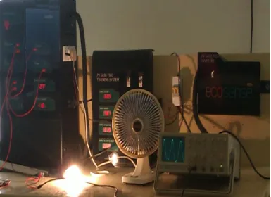
There are two modules of 250 watt power connected in series having 70 volts as DC link voltage. The generated DC voltage is feed to inverter which converts the DC voltage to 210 volts AC. The output of the inverter is connected to the micro grid through point of common coupling. When the DC link voltage goes down then the inverter automatically shut down and the system is isolated from the micro grid. Figure.5 shows the hardware configuration of grid tied PV system.
L TX S
PCC
V
Z
I
V
*
(3) rms
V
V
V
V
V
THD
2 5 2 4 2 3 2 2 (7) Where
2 5 2 4 2 3 2 2 21
V
V
V
V
V
V
rms(8)
Distortion factor =
2 2 4 2 3 2 2 2 1 1 1
THD
1
V
V
V
V
V
V
V
rms (9)Power factor= (Displacement factor)*(Distortion
factor) (10)
cos
1 rmsV
V
r
Powerfacto
(11)Fundamental voltage V1
V1=Vrms
2
1
THD
(12)Fundamental current I1
I1=Irms
1
THD
2 (13)Apparent power S=
P
2
Q
2 [image:4.595.298.551.225.692.2]International Journal of Innovative Technology and Exploring Engineering (IJITEE) ISSN: 2278-3075, Volume-8 Issue-8, June 2019
Table 4 shows voltage sag at PCC according to change in transmission line inductance for different loadsWhenever load rises the voltage sag also becomes higher. Due to the increase in distance also the voltage at PCC may become reduces. By changing the transmission line inductance it is possible to increase the distance of the transmission line.Figure. 6 shows the change in THD according to the change in transmission line inductance for linear loads, observed that with the increase in transmission line inductance it is possible to reduce THD in current.Table. 5 is the observation table for voltage THD, current THD, distortion factor, power factor according to the change in capacitance of the capacitor bank. Observed that with the increase in capacitance of the capacitor bank it is possible to
reduce voltage THD and hence improves the power factor with the cost of increase in current THD.Figure.7 is the graphical representation of voltage and current THD according to the change in capacitance of the capacitor bank.Total generated power= [number of modules × maximum power × solar irradiance × number of days]/ 1000.Table. 6 shows the information about monthly solar irradiance, number of sunny days at RVRJCCE location, according to irradiance level power generation capability is predicted and measured. Observed that almost 28% difference is there between predicted and actual power generation due to the poor efficiency of the solar power inverter, lack of current controller.
[image:5.595.123.508.255.535.2]
Figure.5 Hardware configuration of PV grid tied system Table 2 . Voltage and current THD for linear loads
Table 3 . Voltage and current THD for nonlinear loads
4. Change in voltage at PCC according to change in load
S.No Inductance
(milli henry)
Voltage THD (%)
Current THD (%)
1 0 3 32
2 1 4 26
3 3 8 20
Figure. 6 Change in voltage and current THD according to inductance
Table 5. Voltage, current THD and power factor according to the change in capacitance of capacitor bank
Figure. 7 Voltage and current THD according to change in capacitance of the capacitor bank
S.No Load type and range
Voltage before loading (volts)
Inductance (milli henrys)
Voltage at PCC (volts)
Voltage Sag (volts)
1 Linear 30 watts 210 0 209.5 0.5
2 Linear 100 watts 210 0 208 2
3 Linear 30 watts 210 3 207 3
4 Linear 100watts 210 3 205 5
5 Nonlinear 30
watts
210 0 205 5
6 Nonlinear 100
watts
210 0 202 8
7 Nonlinear 30
watts
210 3 204 6
8 Nonlinear 100
watts
210 3 201 9
S.No Capacitance of the capacitor bank
Voltage THD (%)
Current THD (%)
Distortion factor
Power factor
1 0 3 8 0.996 0.96
2 1 4 10 0.994 0.97
3 3 5 12 0.99 0.98
[image:6.595.100.499.413.684.2]International Journal of Innovative Technology and Exploring Engineering (IJITEE) ISSN: 2278-3075, Volume-8 Issue-8, June 2019 Table.6 Predicted and measured power generation in kwh
Month Solar irradiance
in kwh/m2/day
Number of sunny days
Predicted generation in kwh
Measured power generation in kwh
January 5.59 27 75.465 45.23
February 6.54 29 94.83 62.52
March 5.93 29 85.98 52.45
April 6.7 30 100.5 82.68
May 6.1 20 61 50.67
June 3.77 4 7.54 6.92
July 2.89 2 2.89 2.35
August 3.09 7 10.81 7.56
September 4.05 4 8.1 5.59
October 4.26 18 38.34 30.22
November 5.52 25 69 49.99
December 5.48 23 63.02 52.86
VII. CONCLUSION
A 500 watts grid connected PV system has been monitored along the year and its performance was assessed. Total annual expected generation is 617.475 kwh but the actual generation from the connected system is 449.04kwh due to low inverter efficiency, always the connected inverter at any time maintaining only 70 to 80 percent of efficiency. Due to sudden failure of grid generally the inverter may off, to avoid the shutting down of inverter running the grid tied PV system using virtual grid is discussed and remedial measures are given for the sudden grid failure. By changing the inductance of transmission line with linear and nonlinear loads voltage sag at point of common coupling is tabulated and observed by increasing the inductance of the transmission line the current THD may get reduced with the cost of voltage THD and voltage sag at PCC. The system performance is analyzed by increasing the capacitance of the capacitor bank and observed that by changing the capacitance of the capacitor bank voltage THD may get reduces but the current THD may get increases and the power factor also may get improved.Further studies can be made to develop the better controlling technique of the inverter and hence the inverter efficiency. Identified that it is not possible to get better voltage and current THD with only the transmission line inductance and filter capacitance.To encourage the power generation through solar cell this study is very much useful to the persons nearby areas with the irradiance table.
REFERENCES
1. Munir S and Yun Wei Li, “Residential distribution system harmonic compensation using PV interfacing inverter ,” IEEE Transactions on smart grid, vol. 4, Issue 2 , March 2013, pp. 816-827.
2. F. Blaabjerg, R.Teodorescu, M.Liserre, A.V.Timbus, “Overview of control and grid synchronization for distributed power generation systems,”IEEE Transactions on Industrial Electronics, vol. 53, Issue 5, 2006, pp. 1398-1409.
3. Sohaib Tahir, Jie Wang, Mazhar Hussain Baloch and Ghulam Sarwar Kaloi, “Digital Control techniques Based on Voltage Source Inverters in Renewable Energy Applications: A Review,” MDPI Electronics Journal,2018,pp.1-37.
4. Yi Fei Wang and Yun Wei Li, “A grid fundamental and harmonic component detection method for single-phase systems,” IEEE Transactions on power electronics, vol .28, Issue.5, May 2013,pp.2204-2213.
5. Monfared M, Sanatkar M and Golestan S, “Direct active and reactive power control of single-phase grid-tie converters,” Power Electronics, IET 5(4),pp. 1544-1550.
6. Thacker T, Boroyevich D, Burgos R and Wang F, “Phase locked loop noise reduction via phase detector implementation for single-phase systems,” IEEE Transactions on industrial electronics, vol .58, Issue.6, 2011,pp.2482-2490.
7. J. Rocabert, A. Luna, F. Blaabjerg and P. Rodriguez,“ Control of Power Converters in AC Micro grids,” IEEE Transactions on power electronics, vol .27, Issue.11, 2012,pp. 4734-4749.
8. F. Cupertino, E. Lavopa, P. Zanchetta, M. Sumner and L. Salvatore,“ Running DFT-based PLL algorithm for frequency, phase, and amplitude tracking in aircraft electrical systems,” IEEE Transactions on industrial electronics, vol .58, Issue. 3, 2011,pp. 1027-1035.
9. G.-C. Hsieh and J. C. Hung, “Phase-locked loop techniques- A survey”, IEEE Transactions on Industrial Electronics,vol 43, Issue.5, 2006, pp.609–615.
10. F. Blaabjerg, R. Teodorescu, M. Liserre and A. V. Timbus, “Overview of control and grid synchronization for distributed power generation systems”, IEEE Transactions on Industrial Electronics, vol 53, Issue.5, 2006, pp.1398–1409.
11.S. Golestan, M. Monfared and F. D. Freijedo, “Design-oriented study of advanced synchronous reference frame phase-locked loops”, IEEE Transactions on power electronics, vol .28, Issue.2, 2013,pp. 765-778. 12.D. Velasco, C. Trujillo, G. Garcera and E. Figueres, “An Active
Anti-Islanding Method Based on Phase-PLL Perturbation”, IEEE Transactions on power electronics, vol .26, Issue.4, 2011,pp. 1056-1066. 13.S. A. Oliveira da Silva, R. Novochadlo and R.A. Modesto, “Single-phase PLL structure using modified p-q theory for utility connected systems”, in Proc. IEEE Power Electron. Specialists. Conference (PESC 2008), 2008,pp. 4706-4711.