Parametric design as information modeling tool
in dynamic architecture
Olga Bukunova1,and Konstantin Shumilov1
1 Saint Petersburg State University of Architecture and Civil Engineering, Faculty of Civil Engineering, 190005 2-ya Krasnoarmeiskaya st. 4, Russian Federation
Abstract. Dynamic architecture is a separate upcoming trend in educational process. The article gives examples of parametric software languages development built into graphic packages. The implementation is carried out within the framework of improving the educational process of training specialists in the construction profile with the aim of implementing the program of the digital economy and information modeling technology in construction. Visual programming allows you to create programs without directly writing code by means of graphical objects manipulation. At present, parametric design can be referred to a young and rapidly developing sphere. Essential condition for its further development is availability of trained specialists of respective qualification.
1
Introduction
"The new oil of economy is the data … Digital economy is about how we create, transmit, store, protect and process this data and make well thought out and high-quality decisions based on this data" [1]. The draft program contains nine branches: governing, data infrastructure, research and development, control system, personnel and training, data security, management, "Smart City" and digital healthcare [1]. The first experience with digital economy system development associated with information modeling knowledge technologies (Building Information Modeling – BIM) proved to be positive; it was possible to gain at once four positive parameters in the development of construction industry in Great Britain [2]. To create systems that can work in the real world, a new discipline has appeared – model engineering [3].
A separate perspective direction is a dynamic architecture in the design of buildings. Today, the dynamics in architecture can be used to give buildings a futuristic look and aesthetic properties. Such buildings are resistant to the effects of natural conditions and can perform functions uncommon for structures with a fixed structure. The architecture of the future shall comply with the demands of modern society and change dynamically with the change of its demands. One of these trends is the dynamic architecture that can comply with this demand.
Russia needs to update the process of construction specialists training accounting for modern demands. It is suggested to extend possibilities of information modeling of buildings by using parametric software languages built into graphic packages. For further
development of parametric design it is necessary to have competent personnel capable of developing new technologies. Studying the possibilities of parametric programming in the learning process will provide benefits to graduates in the field of construction.
2
Revit as a Parametric Platform
Traditionally for buildings modeling geometry elements with known coordinate values were used. The process of editing manually is laborious, leading to numerous errors. Later parametric modeling supported systems appeared [4]. In this case a mathematical model of the object with adjustable parameters is created. Alteration of these parameters allows simplifying editing process and decreasing the number of errors.
Two main technologies are used in digital parametric modeling. One of them is based on saving of history of changes (repeating the actions for model and its components creation). The other one supports conditions for the possibility of geometry alteration and is called variational, or dimensional model [5].
When using variational parameterization, parametric connections and restraints which represent a system of equations setting dependencies between parameters are imposed on the object sketch. When using geometrical parameterization, the model is based on architecture components and display elements. In this technology, the object geometry is recalculated in case of its parameters and variables, as well as parent object position, alteration. As a result, geometric parameterization allows for a more flexible model editing mechanism [6].
Revit as a parametrical platform can become the main tool for future construction engineers. The essence of Revit design is generation of dependencies between building components and their implementation and introduction into model. Revit in future shall become as habitual for students as Word text editor or Excel electronic worksheets. That is why students shall study these software programs for a period of several terms. As of today there are two most common platforms for visual programming in design and architecture: Autodesk Dynamo and Grasshopper. Some others are also available in the market:
Teklamo (allows transmitting data from a program created in Dynamo);
Geometry Gym (allows transmitting data from Grasshopper to Tekla).
The use of such programs ensures closer connection between architecture and structure design processes and also allows more effective development of complex geometry structures, computerizing engineering design, transferring data bases between design engineers, working with data bases, automatic formatting of drawings, specifications and cost estimations [7, 8].
On the one hand, digital design simplifies design process and helps to avoid functional errors; on the other hand, it promotes the creation of avant-garde, innovative forms of buildings. It should be noted that building parametric model facilitates designing even in an educational project.
3
Studying the built-in graphical packages of parametric
programming languages by students
Dynamic architecture is a separate upcoming trend in educational process. In order to make the building move, designers use bottom-up stitches of independent floors on a solid foundation, there are blades between them, through which the wind passes, this causes the floors to move and still generates energy. The facade of the building does not have a clear architecture; it constantly acquires various forms [9]. In this «moving» design it is important to employ super hard materials; for the framework metal columns and monolithic
overlap are used. They are not only very strong and convenient in construction but also are not very expensive which is obviously important for even a project of 60 floors.
Despite the fact that this idea appeared in the twenties of the twentieth century, its popularity has grown in recent decades. This is due to development of computer technologies on the whole and visual programming in particular [10]. Visual programming practically needs no programming experience and allows after a short training to create user scripts for students of technical specialties with an analytical mindset. Visual programming allows creating programs without directly writing code by means of manipulation of graphical objects.
Dynamo (it is a Grasshopper analogue for its Rhino modeling tool) is an application on Revit for object modeling. Dynamo is provided with built-in Python which with the help of Revit API DataBase can receive any data on current object, properly process it (e.g., convert into Excel) and return it to Revit in a different form and with respect to other objects.
Thus, Dynamo is not only a small mechanization tool for Revit. Dynamo allows significant extending of standard software framework and increasing efficiency of its operation. With the help of Dynamo students can be taught new activities in Revit: build geometry, work with data, update properties and even send electronic letters. The application can import/export different data (Excel tables, raster displays, text files). Dynamo consists of two spaces combined in one window: programming space and that of geometry with the possibility of their mutual switching. Because of its novelty, Dynamo application is not yet widely spread but its high potential allows recommending this platform for study at the university.
Dynamo is a platform (a kind of ladder) that allows every engineer to transit from the user environment into that of developing own design tools. In some respect it is an analogue of VBA language built into MS Office, enabling to create macros to automate
workstations and optimize and simplify user’s life. Dynamo allows automation of practically all routine processes in geometry construction, formation of documentation, calculation and etc. The application is useful for all section designers. At the first level it is quite possible to use standard nodes (though their number increases rapidly with each new version and due to settings created by users). At the second level it is already possible to write codes in Design Script. At the third level it is possible to write codes in Python and get access to API, thus reaching the same level of those serious programmers who do not treat Dynamo as serious software.
4
Example of Use
Let us consider Dynamo application resources at the example of three-dimensional object construction with standard nodes as well as with DesignScript and Python.
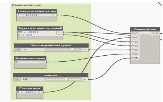
I. Architectural object is a tower.
The object – tower – was constructed by writing code in Python language and partially nodes were used to borrow flooring type from Revit and demonstrate tower turning and narrowing.
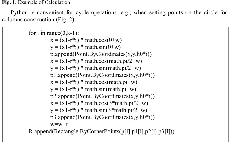
Initial data: number of floors, storey height, side of flooring, number of columns, building angular sweep, coefficient of narrowing, side of core.
Two types of nodes were used to input initial data: Code Block (ensures possibility of DesignScript code direct creation), Integer Slider (regulator creating integer values).
Fig. 1. Example of Calculation
Python is convenient for cycle operations, e.g., when setting points on the circle for columns construction (Fig. 2).
Fig. 2. Execution of Cycle Operations for i in range(0,k-1):
x = (x1-r*i) * math.cos(0+w) y = (x1-r*i) * math.sin(0+w)
p.append(Point.ByCoordinates(x,y,h0*i)) x = (x1-r*i) * math.cos(math.pi/2+w) y = (x1-r*i) * math.sin(math.pi/2+w) p1.append(Point.ByCoordinates(x,y,h0*i)) x = (x1-r*i) * math.cos(math.pi+w) y = (x1-r*i) * math.sin(math.pi+w) p2.append(Point.ByCoordinates(x,y,h0*i)) x = (x1-r*i) * math.cos(3*math.pi/2+w) y = (x1-r*i) * math.sin(3*math.pi/2+w) p3.append(Point.ByCoordinates(x,y,h0*i)) w=w+t
R.append(Rectangle.ByCornerPoints(p[i],p1[i],p2[i],p3[i])) H=(k-1)*h0-h0 /tower height/
x1 = A/pow(2,0.5) /radius of circle/
s=x1-r*(k-1) /radius of circle alteration for building columns/ x2 = s/pow(2,0.5)-500 /radius of circle for guidelines construction/ x3 = B*pow(2,0.5)
arr=[]
The same way pairs of points were obtained for column guidelines construction.
Fig. 3. Column Guidelines Construction
[image:5.482.102.383.213.390.2]Then initial data nodes were connected to PythonScript node (Fig. 4).
Fig. 4. Connection between Initial Data and Main Code Node
Then standard nodes Levels and Structural Column Type (obtaining supporting column level and type from Revit document) were used. With the help of StructuralFraming.ColumnByCurve node columns were constructed by the list of guidelines. To construct core, Wall.ByCurveAndHeight node was used. Floors were constructed with Floor.ByOutlineTypeAndLevel node for flooring creation by curve shape and level from Revit. Curve is obtained from initial code node by using Python Script node.
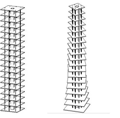
Alteration of sweep angle and tower narrowing coefficient allows online changing object geometric view to be used for further operations with walls, glazing etc.
Figure 5 shows tower view in Revit at sweep angle 0 and narrowing coefficient 0, and Figure 6 indicates the same at sweep angle 60 and narrowing coefficient 0.1.
for i in range(0,q):
x = x2 * math.cos(0+w1) y = x2 * math.sin(0+w1)
kol.append (Point.ByCoordinates(x,y,h0*0)) kol1.append (Point.ByCoordinates(x,y,H))
Fig. 5. Tower View at Sweep Angle 0 and Narrowing Coefficient 0
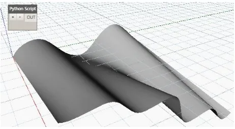
Fig. 6. Tower View in Revit at Sweep Angle 60 and Narrowing Coefficient 0.1. II. The object is envelopment.
Construction of envelopment surface is considered with the help of Python Script node. Surface was constructed with standard PolySurface.ByLoft function (surface construction by loft with curves).
As an example for the first curve k, z=Sin(y) function was used. With cycle for and library function Point.ByCoordinates a set of points was constructed (Fig. 7).
Fig. 7. Set of Points Construction for the First Curve
In a similar way a set of points was generated for the second curve construction z= 2*Cos(y/3) (Fig. 8).
Fig. 8. Set of Points Construction for the Second Curve sur1=[]
for i in range(0,a+1): x = b y = i
z= 2*math.cos(i/3)
sur1.append(Point.ByCoordinates(x,y,z)) sur=[]
for i in range(0,a+1): x = 0 y = i
z= math.sin(i)
[image:6.482.174.373.64.259.2]Fig. 5. Tower View at Sweep Angle 0 and Narrowing Coefficient 0
Fig. 6. Tower View in Revit at Sweep Angle 60 and Narrowing Coefficient 0.1. II. The object is envelopment.
Construction of envelopment surface is considered with the help of Python Script node. Surface was constructed with standard PolySurface.ByLoft function (surface construction by loft with curves).
As an example for the first curve k, z=Sin(y) function was used. With cycle for and library function Point.ByCoordinates a set of points was constructed (Fig. 7).
Fig. 7. Set of Points Construction for the First Curve
In a similar way a set of points was generated for the second curve construction z= 2*Cos(y/3) (Fig. 8).
Fig. 8. Set of Points Construction for the Second Curve sur1=[]
for i in range(0,a+1): x = b y = i
z= 2*math.cos(i/3)
sur1.append(Point.ByCoordinates(x,y,z)) sur=[]
for i in range(0,a+1): x = 0 y = i
z= math.sin(i)
sur.append(Point.ByCoordinates(x,y,z))
[image:7.482.126.357.107.234.2]Then NurbsCurve.ByPoints function is used to construct two curves by obtained points and Loft surface (Fig. 9).
Fig. 9. Loft Surface
For comparison, spherical surface was constructed and on its example the combination of Python Script node and standard nodes from Dynamo library was considered. Two radii were given as initial data. The first one is the radius of surface base; the second is radius of surface convexity.
As in the previous example, surface was constructed with Python Script node. Python Script node body contains required libraries, initial data and required number of points is set (q).
Surface was constructed with Surface.ByRevolve function (surface creation by profile graph shifting around axis radius representing axis vector starting at the point start_angle in degrees and finishing at sweep_angle).
[image:7.482.57.419.398.476.2]With for cycle and Point.ByCoordinates function, array sur of circle points was formed. Then with NurbsCurve.ByPoints function these points were joined into a circle (Fig. 10).
Fig. 10. Surface Construction for i in range(0,q+1):
x = R1 * math.cos(0+w1) y = R1 * math.sin(0+w1)
sur.append(Point.ByCoordinates(x,y,z)) w1=w1+qq
Successively surface was constructed and displayed for different data variants (Fig. 11).
Fig. 11. Surfaces with radius of surface base 100, Radius of surface convexity 50 and 100
With the help of Surface.Thicken function, obtained surface thickness is set. With the help of Surface.Area and Surface.Volume surface area and volume are obtained.
Constructed envelopments are exported to Revit as well as special calculation packages for permissible loads analysis, structure reliability estimation, etc.
The above mentioned examples show how convenient and brief is the combination of standard nodes with Python Script node. Firstly, it is easy to alter initial data without disturbing the main code. Secondly, thanks to standard nodes Number and Integer Slider it is possible to visually follow object shape alteration at different values of initial data. Thirdly, as the main part of surface construction is written inside Python Script node body, there is no huge amount of nodes and their interconnections, script processing and complex phrase construction time decreases substantially.
As a result of executed work possibilities of drafting program Revit extension were analyzed with comparatively new tool – Dynamo customization code. An important feature of the tool is the possibility of creating and modeling of three-dimensional objects not only with standard node library but also by writing own code. Optimum solution is combination of standard nodes from Dynamo library and nodes with own code.
Use of Python Script is mostly advisable for complicated calculations, implementation of multiple cycle operations and object transformations (creation and rotation of floors, design elements, calculation of point coordinates during modeling of envelopments, etc).
Besides Python, there is also a programming language – Design Script, but it is not low-level, it operates only internal and only base nodes without access to external API, directly. Rhino + Grasshopper is a more publicly available source, more established, has more textbooks and a lot of updates and plug-in software including physics imitation, evolutionary problem solver and other important tools. The combination is convenient for small projects with complicated parametrical detailing, sophisticated architectural design and imitation. It interacts with Grasshopper ArchiCAD.
Choice of software also depends on its demonstrativeness. There is no need to use graphical programming if it is possible not to parameterize elements. In the next few years all the three platforms (Dynamo + Revit, Rhino-Grasshopper + ArchiCAD, Marionette in Vector works) are expected to continue expanding their functionalities into respective solutions so as to cover as many BIM applications as possible. It will include reception and introduction of data on any element (implementer or documentation element), views and representations, histories, attributes, drawings, model sets, time-tables, publications. The main focus is on construction elements and then come all other program areas. In a few
years it will be possible to produce all automated items in ArchiCAD with Grasshopper [11].
5
Conclusion
The design methods suggested support the new trend – dynamic architecture. Dynamic architecture has a number of features distinguishing it from common construction. The first peculiarity is connected with construction shape that permanently undergoes changes, adapting to weather conditions [9]. The second peculiarity is the dynamic construction method. Usually such structures are made up of pre-fabricated parts that are manufactured at plants and get to site pre-fabricated. The third feature of dynamic buildings is the fact that they combine modern technologies and preserve environment. Dynamic buildings are also capable of producing power for their independent power supply, e.g., from wind power. The next feature comprises functionalities, e.g., bridges in which central part can be lifted. This type can be attributed to the new stadium Krestovsky in St. Petersburg, which has a retractable roof, which is very convenient for bad weather, and the field of the stadium is pushing beyond its limits.
On the basis of dynamic architecture design and construction experience analysis carried out, a number of dynamic architecture advantages have been identified. First, it is the reduction of construction time. It takes about three weeks to construct a storey using common technique and it only takes three days for moving structure, entire building construction period will decrease up to 18 months (standard construction takes about 30 months). Second, in such a project the number of workers can be decreased. And at last expenditures can be saved on building machinery. It will be necessary at construction initial stage, during building core construction; no special machinery will be required during storey stringing.
That is why it is so important to use applications allowing construction objects modeling in training. At present, parametric design can be referred to as a new but rapidly developing sphere. Its employment in training process facilitates establishment of new architectural thinking, and it is made up on new information technologies. Essential condition for its further development is availability of trained specialists of respective qualification and innovation and software that will make it possible for all architects and builders using new technologies to study parametric design. Mastered new parametric design capabilities will give advantages to engineering students [5]. Dynamic trend is just beginning to actively develop and get implemented into construction. This is a new dawn in architecture. And if its active growth continues, in 20 years the world will change beyond recognition.
References
1. O. Pavlenko, E. Kazachenko, Digital Economy Programme will Turn Data into New Oil, Conclusions [online], Available at: http://tass.ru/ekonomika/4279297 (2017) 2. A. P. Dobrynin et al., International Journal of Open Information Technologies, 4 (1)
(2016)
3. V. P. Kupriyanovskiy, D. E. Namiot, S. A. Sinyagov, International Journal of Open Information Technologies, (4) 2 (2016)
5. O. V. Bukunova, A. S. Bukunov, Innovative Science: Collection of Articles on V International Research and Practice Conference Materials “MtsNO”, 4(5) (2017) 6. F. J. Sabongi, The Integration of BIM in the Undergraduate Curriculum: an Analysis of
Undergraduate Courses [online], Available at: http://www.ascproc.asc-web.org (2009) 7. M. M Joannides, R. A. Issa, S. Olbina, Journal of Building Information Modeling
(2011)
8. H. Abdirad, C.S. Dossick, Journal of Information Technology in Construction (ITcon), 21 (2016)
9. C. Salter, Entangled: Technology and the Transformation of Performance (The MIT Press, Cambridge, 2010)
10. Seok-Heon Yun, Ki-hyun Jun, Chang-baek Son, and Sang-chul Kim, Journal of Civil Engineering, 18 (2) (2014)