International Journal of Innovative Technology and Exploring Engineering (IJITEE) ISSN: 2278-3075, Volume-9 Issue-2, December 2019
Adapting the Effect of Asynchronous Impulsive
Noise using Interleaving Based on Compound
Signal Classification in Broad Plc
Smitha Gayathri D , Usha Rani K R
Abstract: Power Line Communication (PLC) is a technology which transforms the power line into pathways for the conveyance of broadband data. It has the advantage for it can avoid new installation since the current installation used for electrical power can also be used for data transmission. However, this power line channel presents a harsh environment for data transmission owing to the challenges of impulsive noise, high attenuation, selective fading and etc. In this paper to provide special structure to signal in frequency domain we have applied interleaving of signal in time domain. Based on the special structure, IN support is determined by using compound signal classification (CSC) and its amplitude is estimated by Least Squares (LS) method in frequency domain, exploiting the noise information on null subcarriers in Discrete Multitone Transform (DMT) system.
I. INTRODUCTION:
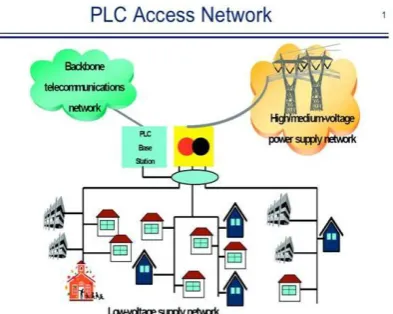
The demand for broadband in education, health, entertainment, gaming, advertising, business and home networking has increased tremendously over the years. A broadband access network includes wired line, wireless and satellite. In wired line network, new installation of cables such as coaxial, UTP Cat-5, UTP Cat-6 and optic fiber are required and devices are plugged directly into a modem or router for broadband access, this is referred to as wired LAN. The ever increasing demand for broadband leads to the consideration of transmitting broadband data on power line network. Power line communications (PLC) have become an attractive communication solution for smart grid and other applications due to their advantages of high penetration and low deployment costs over other communication technologies [1–3]. The applications of PLC, however, are limited by some unfavorable factors, among which the impulsive noise (IN) is the major factor that influences the data transmission over power grid. Asynchronous impulsive noise is primarily caused by switching transients of electrical appliances and characterized by short duration and high power impulses with random arrivals. Periodic impulsive noise typically arises from switching mode power supplies and contains longer bursts of interference spikes that occur periodically with half the main cycle of grid.Power Line Communication
Revised Manuscript Received on December 05, 2019.
Smitha Gayathri D , Assistant Professor ECE Department, Don Bosco Institute of Technology, Bangalore.
Usha Rani K R, Associate Professor ECE Department, RVCE,
(PLC) is a technology saddled with the responsibility of transforming the standard electric power network into a communication pathway. Hence narrowband/broadband information can be transmitted over its entire length to every device in use on the grid/network and to every user outlet(Yousuf, Rizvi, Arabia, & El-shafei, 2007). It is the technology implementing the existing house wiring to provide broadband internet access. Thus, high-speed internet access points are achieved of every electrical outlet in the house. New cable installation is therefore not necessary. PLC can assume two types of architecture; narrowband and broadband architectures (Korki, Hosseinzadeh, Vu, Moazzeni, & Foh, 2011). Narrowband PLC frequency spectrum is from 3 to 148.5 KHz in Europe and can be above 500 KHz in the US. Its data rate is in Kbps over a maximum distance of 1 Km, (Katayama, Yamazato, & Okada, 2006). Broadband PLC has a wider spectrum spanning from 1 to 30 MHz, thus, 1-15 MHz for outdoor applications and 15-30 MHz for indoor applications. Its data rate is 300 Mbps, (Korki et al., 2011).Discrete multitone is a multicarrier modulation technique where a high speed serial data stream is divided into multiple parallel lower speed stream streams and modulated onto sub-carriers of different frequencies for transmission.Discrete multitone (DMT) is a method of separating a Digital Subscriber Line (DSL) signal so that the usable frequency range is separated into 256 frequency bands (or channels) of 4.3125 KHz each. DMT
uses the fast Fourier transform
(FFT) algorithm for modulation and de-modulation. Dividing the frequency spectrum into multiple channels allows DMT to work better when AM radio transmitters are present. Within each channel, modulation uses quadratude amplitude modulation (QAM). By varying the number of bits per symbol within a channel, the modem can be rate-adaptive. Both G.DMT and G.Lite use DMT.
II. LITERATURE SURVEY:
[1]. The work of (Zahedpour, Feizi, Amini, Ferdosizadeh, & Marvasti, 2008) focused on removing additive impulse noise using the zeros in the Discrete Fourier Transform (DFT) domain. In this model, there is need for reconstruction of each impulsive noise, this is done with two information; location and amplitude of the impulsive noise. The method implemented is called Recursive Detection Estimation (RDE). This system consists of
Classification in Broad Plc
sample and the average of its neighbors. A non detection of a corrupt signal is considered a missed detection and it leads to a false alarm. So a binary mask is generated, zero, if impulsive noise is detected and one if otherwise. Iterative method on the other hand removes the impulsive noise by using the binary mask generated in the detection block and reproducing the original signal, this signal is reconstructed faster than noise. The half capacity (one fourth of the number of DFT zeros of the signal) had SNR improvement over the full capacity (half of the number of the DFT zeros of the signal) over different steps of RDE, when hard-limiting and low-pass processes were repeated in simulation as shown in figure 1.
[image:2.595.309.536.203.338.2]Figure 1 Impulsive noise cancellation using hard-decision and simple detector (Zahedpour et al., 2008) [2]. Two methods/apparatus were implemented by Ribeiro et al. (Ribeiro, Lopes, Romano, Member, & Duque, 2006) to model the transfer characteristics of the power line, these are bottom up and top down. The DMT symbol is then computed by passing the DMT transmitter vector through an N x N Inverse Discrete Fourier Transform (IDFT) matrix. The strategy implemented is a process intended at reducing signal noise power as this will increase the SNR of the system and thus increase the bit-rate capacity. The technique is a modified PLC-DMT, where a technique evolving from computational intelligence is used to mitigate the non- gaussian noise in the PLC. Multilayer Perception Neural Network (MLPNN) as a particular case of a computational intelligence, was used for the reduction of non-gaussian noise, this choice was due to the neural network's ability to learn nonlinear features from the data available and thus remove corrupted signal from the non-linear component. PLC-DMT shows that MLPNN successfully reduce the impulse noise at the output of the power line, yielding a background noise PSD of -120 dB/Hz, impulse noise PSD of -90 dB/Hz when the transmitting signal PSD is - 70dB/Hz. The obtained simulation results reveals that MLPNN results in an SNR increase, with an improvement of 5 dB and figure 17 shows its bits rate improvement over the PLC-DMT. The method presents a complexity when compared with other computational techniques of optimization.
Figure 2 M-PLC-DMT and PLC-DMT performances in terms of the length of a shortening equalizer for PL
channel (Ribeiro et al., 2006)
[image:2.595.50.284.213.301.2][3]. Various methods of time domain technique were adopted by different Authors to mitigate impulsive noise in PLC. A signal level limiter was implemented in Kim et al. (Y. Kim et al., 2008) to mitigate impulsive noise in coherent M-ary PSK and different MPSK of PL system. Signal level limiter, a simple non-linear function in the received time domain was carried out at three estimation scenarios, namely, least square, perfect channel and one-tap equalized channel estimations. The method achieved a 1 dB improvement in SNR (figure 3) over the one-tap equalization channel estimation, although the improvement is small.
Figure 3 Kim et al Impulsive noise mitigation result (Y. Kim et al., 2008)[4]Ndo et al. (Ndo et al., 2010) achieved
a 2.9 dB and 5 dB SNR
the two test scenarios considered, heavily and weakly disturbed respectively as shown in figure 6, using an automatic adaptive procedure of mitigation. This method involves the derivation of Bernoulli Gaussian (BG) noise parameters and clipping threshold updating according to the BG noise parameter value. The achievement recorded was with an increase in overhead in circuit complexity
Figure 4 Ndo et al. Impulsive noise mitigation result (Ndo et al., 2010)
SYSTEM MODEL:
[image:2.595.310.524.471.606.2]Adapting the Effect of Asynchronous Impulsive Noise Using Interleaving Based On Compound Signal Classification in Broad Plc
[image:3.595.62.259.54.211.2]The complex baseband model for DMT-based PLC systems is shown in Figure 5.
Figure 5: Block Diagram of proposed method At the transmitter, the generated bit stream bk is mapped into complex symbols by quadrature amplitude modulation 4 (QAM4), and then modulated onto multiple carriers frequencies by DMT technique. The ouput of DMT in time domain is interleaved and cyclic prefix is added before transmitting over power line channel.At the receiver, Cyclic prefix is removed from received signal and then De-Interleaving is done, and then demodulated into original transmitted symbol, and finally it is de-mapped into bit stream. IN is estimated and then mitigated from received signal. In our discussion, we mainly focus on the IN mitigation, assuming that power line channel is frequency flat for all the subcarriers.
III. DATA ACQUISITION:
Data acquisition and conversion systems are used to acquire analog signals from one or more sources and convert these signals into digital form for analysis or transmission by end devices such as digital computers, recorders, or communications networks.
Input data will be converted to corresponding binary bits to process further.
QAM-4 Mapping
As in many digital modulation schemes, the constellation diagram is useful for QAM. In QAM, the constellation points are usually arranged in a square grid with equal vertical and horizontal spacing, although other configurations are possible (e.g. Cross-QAM).
Since in digital telecommunications the data is usually binary, the number of points in the grid is usually a power of 2. In QAM Mapping we will convert the input data into complex number symbols.
DMT:
Discrete multi-tone (DMT) is a method of separating a Digital Subscriber Line (DSL) signal so that the usable frequency range is separated into 256 frequency bands (or channels) of 4.3125 KHz each. DMT uses the fast Fourier transform (FFT) algorithm for modulation and demodulation. Dividing the frequency spectrum into multiple channels allows DMT to work better when AM radio transmitters are present. Within each channel, modulation uses quadratude amplitude modulation (QAM). By varying the number of bits per symbol within a channel, the modem can be rate-adaptive.Advantage of DMT is that the carriers can be adjusted to different degrees in the transmission power. This makes it possible to compensate for the non-ideal frequency response of specific telephone lines.
Interleaving
[image:3.595.307.526.572.722.2]Interleaving is used to convert convolutional codes from random error correctors to burst error correctors. The basic idea behind the use of interleaved codes is to jumble symbols at the receiver. This leads to randomization of bursts of received errors which are closely located and we can then apply the analysis for random channel. Thus, the main function performed by the interleaver at transmitter is to alter the input symbol sequence. At the receiver, the de-interleaver will alter the received sequence to get back the original unaltered sequence at the transmitter.Interleaving is done at the bit level after the bits come out of the encoder. It’s not really time or frequency domain, but bit domain. Later on these bits get mapped to constellation positions in the frequency domain, and then those constellation positions get mapped to one or more DMT symbols in the time domain. So an interleaved bit could end up getting displaced in both frequency and time potentially.Impulsive noise in PLCNoise in PLC can be modeled by using Middleton's class a noise model. Two types of noise, background and impulsive noises are visible in this model. The background noise follows Gaussian distribution, while the impulsive noise is a noise that arrived according to Poisson distributed random sequence. Analysis of the effects from these noises on DMT-based PLC system shows that the background noise can be modeled as AWGN with zero mean and variance, and the impulsive noise is given by (K. S. Al-mawali, Sadik, Hussain, & System, 2009):
Figure 6: Impulse Noise in PLC
Impulsive noise is the noise that poses the most severe threat to digital signal in Power Line Communication system, as it comes in burst form, thus
Classification in Broad Plc
impulse noises will a great deal render the power line a more decent medium for broadband data transmission. This will enhance the acceptability of the medium, since it is easy to install and readily available.
Impulsive noise Modeling
Impulsive noise as described above poses the most severe threat to broadband signal transmitted on the power line network. This is so because the impulsive noise arrives randomly, spanning through microseconds to milliseconds, with a power spectral density (PSD) that is above the background noise. Owing to this characteristic, the impulsive noise has capacity to corrupt the signal being transmitted through power line network. Combating this noise in PLC will go a long way to achieving serenity of the power line used as its medium of propagation. Therefore, mitigating impulsive noise in PLC is a worthwhile activity. Noise Modeling Based On CSC
In DMT PLC systems, null subcarriers are reserved and can be used for IN estimation because they only include noise information. Noise mitigation based on CSC attempts to recover IN from the information on null subcarriers.
The interleaved received signal 𝑟′ can be 𝑥𝛼 regarded as
superposition’s of M sequences as x_, with 0<=𝛼 ≤ 𝑀 − 1. In light of (11), the interleaved received signal in the frequency domain can be expressed as
R’(J𝑚) + 𝑗 ) = 𝑀−1X𝛼(J𝑚 ) + 𝑗 ) 𝛼 =0
= 𝑀−1 X 𝑗 e𝛼 −iN2πj α
𝛼=0 e−iM
2πm α
…..1
where R’ represents the FFT of the interleaved received signal 𝑟 . If 𝑗 remains unchanged, the jth element in each segment can be rewritten in matrix form in (3). Covariance Matrix Eigenvalue Decomposition (ED) When 𝑗 is fixed, R’(𝑗 ) in (23) can be seen as all the collected signals on S antenna at timing 𝑗 . The covariance of the interleaved received signal at timing 𝑗 will be calculated as ...(2)
Where CRR(𝑗 ) = X(𝑗 ) X(𝑗 ) H in (2) and ()H denotes Hermitian operator. The expectation of CRR can be estimated as ...(3)
E{CRR} = BE{CXX}BH...(4)
...(5)
...(6)
The eigen values of E{CRR} are equal to those of E{CXX}, as matrix B is a full rank matrix. After IN interleaving, the frequency spectrum of these interleaved IN sequences can be assumed to be independent, thus deriving ...(7)
according to (6). Therefore, E{CXX} can be expressed as
...(8) Here we give an empirical threshold of 2 for selecting the main Eigen-values, differentiating from those of background noise. It implies that if the averaged power of interleaved sequence is higher than twice the power of background noise, it is detected as an IN interleaved sequence.
The estimated number of all the selected IN interleaved sequences is marked as p^. We select the p^ eigenvectors corresponding to the p^ selected eigen-values to form the subspace matrix SIN. The estimation of ^p was discussed theoretically [12], while it doesn’t perform well in our case because of fewer samples for estimation. Therefore, an empirical threshold is adopted based on statistics, which will be discussed in the simulation. In this step, we only determine the number of IN interleaved sequence and its projection space in the frequency domain. Next, we need to determine the concrete locations of these sequences.
Frequency Estimation (𝜶 Estimation)
The IN projection of each IN interlaved sequence onto time domain with the obtained subspace suffers from minimal interferences from others. The frequency estimation function can be expressed in (9). Since the number of IN interleaved sequences has been determined as p^, 𝛼 values corresponding to the p^ largest
Adapting the Effect of Asynchronous Impulsive Noise Using Interleaving Based On Compound Signal Classification in Broad Plc
...(9)
Where B(𝜶) refers to the 𝐻thcolumn of matrix B, and0<=
𝛼<=M – 1.
IN- estimation based on Least Squares
According to the former discussion, once all the values of 𝑝
IN interleaved sequences are selected as vector 𝑝 , (5) can be reduced as
...(10)
Where 0<= 𝑗 <= j-1 . Since all the elements of 𝑋𝑝 𝛼 are
recovered, we can deduce 𝑋^𝑎 with each estimated elements in 𝛼. 𝑿𝒑𝒋 can be solved using LS method as
...(20) Where 0<= 𝑗 <= j-1. Since all the elements of X^p(𝜶) are recovered, we can deduce with α each estimated element in ^_. Therefore, each IN interleaved sequence is recovered in the time domain by inverse FFT of
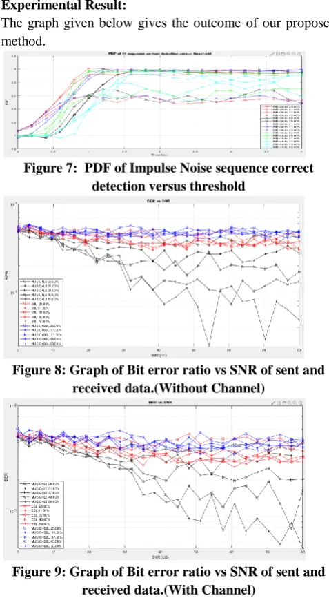
Experimental Result:
[image:5.595.303.536.82.284.2]The graph given below gives the outcome of our proposed method.
Figure 7: PDF of Impulse Noise sequence correct detection versus threshold
Figure 8: Graph of Bit error ratio vs SNR of sent and received data.(Without Channel)
Figure 9: Graph of Bit error ratio vs SNR of sent and received data.(With Channel)
Channel Capacity:
we consider the capacity performance C, which is obtained by applying the Shannon formula under the assumption of colored Gaussian noise with the SNR.
where f1 and f2 are the start and stop transmission frequencies.
IV.
CONCLUSION AND FUTURE WORK
In this paper, IN mitigation with interleaving based on CSC is proposed for IN support detection based on time domain interleaving, with IN bursts assumption. The LS algorithm is applied for IN estimation in the frequency domain. Besides, CSC with SBL based IN support detection is also investigated. The proposed CSC with LS method performs closely to SBL with higher INRs, while its performance degrades because of inaccurate IN support estimation with lower INR. Moreover, CSC with SBL holds advantages of CSC with LS algorithm and SBL method, performing best among three methods. It is also implemented with less computation overhead compared with SBL algorithm.
REFERENCE:
1. L. T. Berger, A. Schwager, and J. J. Escudero-Garzs,”PowerLine
Communications for Smart Grid Applications, JECE, vol. 2013, pp. 1- 16, 2013.
2. D. Anastasiadou and T. Antonakopoulos,” Multipath characterization
of indoor power-line networks,” IEEE Trans. Power Del., vol. 20, no. 1, pp. 90-99, Jan. 2005.
3. J. A. Cortes, L. Diez, F. J. Canete and J. J. Sanchez-Martinez,
”Analysis of the Indoor Broadband Power-Line Noise Scenario,” IEEE Trans. Electromagn. Compat., vol. 52, no. 4, pp. 849-858, Nov. 2010.
4. M. Zimmermann and K. Dostert, ”Analysis and modeling of impulsive
noise in broad-band powerline communications,” IEEE Trans. Electromagn. Compat., vol. 44, no. 1, pp. 249-258, Feb. 2002
5. V. Degardin, M. Lienard, A. Zeddam, F. Gauthier and P. Degauquel,
”Classification and characterization of impulsive noise on indoor powerline used for data communications,” IEEE Trans. Consum. Electron., vol. 48, no. 4, pp. 913-918, Nov 2002.
6. Al-Dweik, A.; Hazmi, A.; Sharif, B. and Tsimenidis, C., ”Efficient
interleaving technique for OFDM system over impulsive noise channels,” 21st Annu. IEEE Int. Symp. Personal, Indoor and Mobile Radio Communications, Instanbul, 2010, pp. 167 171.
7. S. Nayyef, C. Tsimenidis, A. Al-Dweik, B. Sharif and A. Hazmi,”
Time- and Frequency-Domain Impulsive Noise Spreader for OFDM Systems,” 11th Int. Conf. Trust, Security and Privacy in Computing and Communications, Liverpool, 2012, pp. 1856-1861.
8. S. Liu, F. Yang and J. Song, ”An Optimal Interleaving Scheme With
Maximum Time-Frequency Diversity for PLC Systems,” IEEE Trans. Power Del., vol. 31, no. 3, pp. 1007-1014, June 2016.
9. K. S. Al-Mawali and Z. M. Hussain, ”Performance of bit-interleaved
coded OFDM in power line communications with impulsive noise,” Int. Conf. Advanced Technologies for Communications, Hai Phong, 2009, pp. 49-53.
10. N. Andreadou and A. M.
[image:5.595.46.285.326.759.2]Classification in Broad Plc
Impulsive Noise in Power-Line Communications With LT Codes,” IEEE Trans. Power Del., vol. 28, no. 3, pp. 1483-1490, July 2013.
11. T. Shongwe, A. J. H. Vinck and H. C. Ferreira, ”The effects of periodic
impulsive noise on OFDM,” IEEE Int. Symp. Power Line Communications and Its Applications, Austin, TX, 2015, pp. 189-194.
12. S. V. Zhidkov, ”Analysis and comparison of several simple impulsive
noise mitigation schemes for OFDM receivers,” IEEE Trans. on Commun., vol. 56, no. 1, pp. 5-9, Jan. 2008.
13. S. V. Zhidkov, ”Performance analysis and optimization of OFDM
receiver with blanking nonlinearity in impulsive noise environment,” IEEE Trans. Veh. Technol., vol. 55, no. 1, pp. 234-242, Jan. 2006. 14. K. S. Al-Mawali and Z. M. Hussain, ”Adaptive-threshold clipping for
impulsive noise reduction in OFDM-based power line
Communications,” Int. Conf. Advanced Technologies for
Communications, Hai Phong, 2009, pp. 43-48.
15. G. Ndo, P. Siohan and M. H. Hamon, ”Adaptive Noise Mitigation in
Impulsive Environment: Application to Power-Line Communications,” IEEE Trans. Power Del., vol. 25, no. 2, pp. 647-656, Apr. 2010.
16. U. Epple and M. Schnell, ”Adaptive threshold optimization for a
blanking nonlinearity in OFDM receivers,” IEEE Global Communications Conf., Anaheim, CA, 2012, pp. 3661-3666.
17. F. H. Juwono, Q. Guo, Y. Chen, L. Xu, D. D. Huang, and K. P. Wong,
”Linear combining of nonlinear preprocessors for OFDM-based powerline communications,” IEEE Trans. Smart Grid, vol. 7, no. 1, pp. 253- 260, Jan. 2016.
18. F. H. Juwono, Q. Guo, Y. Chen, L. Xu, D. D. Huang, and K. P. Wong,
”On the performance of blanking nonlinearity in real valued OFDMbased PLC,” IEEE Trans. Smart Grid, vol. PP, 2017.
19. K. M. Rabie and E. Alsusa, ”Quantized Peak-Based Impulsive Noise
Blanking in Power-Line Communications,” IEEE Trans. Power Del., vol. 29, no. 4, pp. 1630-1638, Aug. 2014.
20. K. M. Rabie, E. Alsusa, A. D. Familua and L. Cheng, ”Constant
envelope OFDM transmission over impulsive noise power-line communication channels,” IEEE Int. Symp. on Power Line Communications and Its Applications, Austin, TX, 2015, pp. 13-18.
AUTHORS PROFILE
Dr. Usha Rani K R has received a B.E (Electronics
and Communication) in 1989 from Mysore
University, India, and M.E.( Power Electronics)in
1996 from Gulbarga university in 1996, Ph.D
(Power Line communication) in 2014 from Kuvempu University, India.
Prof.Smitha Gayathri D received a B.E. degree inElectronics and Communication engineering in
2006 from Visvesvaraya Technological
University,India and an M.E. degree in
![Figure 3 Kim et al Impulsive noise mitigation result (Y. Kim et al., 2008)[4]Ndo et al](https://thumb-us.123doks.com/thumbv2/123dok_us/8153994.247954/2.595.310.524.471.606/figure-kim-impulsive-noise-mitigation-result-kim-ndo.webp)