International Journal of Innovative Technology and Exploring Engineering (IJITEE) ISSN: 2278-3075, Volume-8 Issue-12, October 2019
Abstract: The process of lifting a ship’s block is one of the important process in shipbuilding. The purpose of lifting or transfering of the blocks is to relocate the block to a new position before joining with other blocks. Prior to the lifting operation of ship’s sub-block, some stress and deflection analysis shall be done, in order to assess the magnitude of the deformation and the stresses acting on the structural members of the block. Based on the assessment, some changes in lifting operation can be intiated for example changing the lifting eye pad location to minimize plate deformation and bucking of structural members. In this study, the structural behaviour of a block was investigated using basic finite element method in order to simulate the deflections and stresses during the lifting operation. The initial dimension of the sub-block that was being investigated are with its dimensions: 21 meters in length, 16 meters in width, 4 meters in height. The type of material of all the structural components used in the sub-block is High Tensile Steel DH36. The investigation used Multiframe software. There are four case studies conducted with varying padeye location and number of lifting eye pads used in a single lifting. The sub block is approximately at 160 tonnes. These results were assessed with the DNV-GL acceptance criteria which can be found in DNV-GL Rules for finite element analysis. The highest yield ulitilization factor was found in case study 3 at 0.864, where it did not comply with the permissible coarse mesh yield utilization factor which is limited to 0.80. The lowest yield utilization factor was found in case study 2 at 0.278.Using the DNV-GL acceptance criteria it is concluded that case study 2 is the best configuration in lifting the sub-block.
Index Terms: Sub-block, lifting, Multiframe, new-building.
I. INTRODUCTION
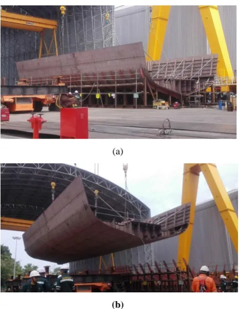
Nowadays, large vessel are being built in modular construction mode or in other word using hull block contruction method (HBCM), where instead building the ship through erection of all structural members and shell plating from the keel upwards, the vessels are being built into blocks, sub-blocks and parts assemblies [1][2]. A block is the largest construction unit, which forms a part of a part of the ship‟s hull. The blocks are assembled from sub-blocks, and the sub-blocks are assembled from parts assemblies. Then once all the blocks are ready, there are brought and welded together to form a single hull or a superstructure. An example of a block ready for joining is shown in Figure 1(a). Prior to welding to join together all the blocks to form a hull, most of the blocks need to be relocated and positioned correctly at the erection site. This operation requires lifting of the block using
Revised Manuscript Received on October 05, 2019.
Iwan Mustaffa Kamal, Maritime Engineering Technology Section, Universiti Kuala Lumpur, Malaysian Institute of Marine Engineering Technology, Lumut, Malaysia.
Roslin Ramli, Maritime Engineering Technology Section, Universiti Kuala Lumpur, Malaysian Institute of Marine Engineering Technology, Lumut, Malaysia.
Mohd Yazid Kamaruddin, Structural Engineering, Megaway Engineering & Trading Pte. Ltd, Singapore.
gantry crane as shown in Figure 1(b). During lifting operation of the blocks or the sub-blocks, the structural behavior of the structural members such as longitudinal and transverse frames, bulkheads, stiffeners, and platings are unknown. This lifting operation may cause plate deformation, and buckling of primary and secondary structural members.
(a)
(b)
Fig. 1 (a) A completed block awaiting for lifting. (b) The completed block being lifted and ready for transfer to the
erection site, later to be joined with the other blocks Prior to lifting operation, some risk assessment are needed in order to determining the magnitude of the deformation and stresses acting on the structural members of the blocks. Based on the assessment, some changes in lifting operation can be intiated for example changing the lifting eye pad location to minimize plate deformation and bucking of structural members. Therefore in this study, the deformation and the stresses of the blocks or sub-blocks were investigated using 3D beam and plate element method. In this study a 3D beam and plate element analysis software, Multiframe was chosen.
This software is available from Bentley Systems [3].
The Structural Behaviour of a Ship‟s Sub-Block
During Lifting Operation
[image:1.595.306.551.231.547.2]This method was chosen over the time consuming full finite-element analysis as it could provide a fast and a reliable static or dynamic analyses of the structural behavior of the members in a block.
There are some recent studies on the structural analysis during block lifting. One of the examples can be found in Misbah et al. [4]. Misbah et al. evaluated the deformations and stresses of a bottom portside block of a tanker with dimensions of 30.5 meters in width x 12 meter in length, and 6 meters in height. The bottom block consists of bottom and inner bottom structures. The bottom structure consists of bottom plate, bottom longitudinal, and bilge plate. The inner bottom structure consists of inner bottom plate and inner bottom longitudinal, with the plate floor, bottom center girder and bottom side girder were installed between the bottom plate and the inner bottom plate. A finite element modelling was used to analyse the stress and maximum deformation during the block lifting process. Eight node shell element was used to model the steel plates and three node beam element was used to model the stiffeners. The bottom structure models were analysed in 4 cases with various lifting eye pad position. The 4th case with the lifting eye pads positioned perpendicular to frame 42 and frame 45 girders, has the maximum deformation at 0.065mm. The 2nd case proved to be the best position of the lifting eye pads, where the eye pads were positioned axially with frame 43 and 44 girders. The result of the deformation is at 0.025mm.
Other examples can be found in Liebert and Rashid [5]. Liebert and Rashid simulated a lifting operation of a portable offshore unit. In their study, they compared two methods, one using a shell model and the other one using beam model. These two models were executed using ABAQUS 6.13 sofware and their own beam model code, based on Timoshenko‟s beam theory, written in MATLAB respectively. As expected the beam model simulated the collapse later than the shell model, where in general it is known that the beam model will be stiffer than the shell model. Liebert and Rashid commented that the reason for this is because the mass is applied to the whole cross section of the structure, which makes the beam model becoming stiffer when deformation take place. Some other examples of using finite element modelling in assessing the structural behavior of ship‟s structural members can be found in Fernandez et al. [6]. He conducted a full finite element analysis to assess the structural behavior of a Aframax oil tanker in intact and damage condition due to grounding using ANSYS® software. For the intact case, only one scenario was done, where the tanker was simulated in full load condition. For the damage condition, three scenarios were simulated by applying a change in the mechanical properties of the material, where the Young Modulus were reduced to 40%, 60%, and 80% from the original value.
II. CASESTUDY The hull block
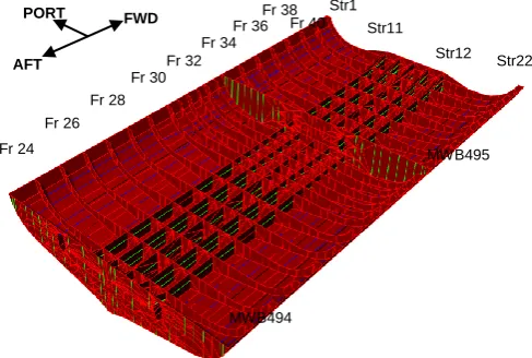
The hull block used for the case study is a bottom engine sub-block of a naval combatant vessel. The sub-block consist of 19 transverse frames, 8 longitudinal frames, 2 main watertight bulkhead as the primary structural members and 22 longitudinal stringers as the secondary structural members
[image:2.595.308.552.93.257.2]as shown in Figure 2. This sub-block is 21 meters in length, 16 meters in width and 4 meters in height. The weight of the sub-block is 160 tonnes.
Fig. 2 The bottom engine sub-block, which consist of 19 transverse frames, 8 longitudinal frames, 2 main watertight bulkheads and 22 longitudinal stringers. The 2
main watertight bulkheads are labelled as MWB494 and MWB495. The transverse frame are labelled from Fr24 to Fr40. The frames number is ascending towards the forward of the sub-block. The stringers are labelled from
Str1 to Str22 Modelling the sub-block
As the sub-block digitized data are only available in the form of 2D „dwg‟ format, a substantial amount of work need to be done to convert all the data to a 3D format. All the single lines in the 2D format need to be edited and converted into surfaces which form all the transverse frames, longitudinal frames, bulkheads, stringers and shell plating.
There were some simplifications were made to the hull block. Some of the support structures were removed such as the collar plate, bracket and bilge keel. Some of the compomemnts such as the engine seating and the generator seating for both port and starboard side were also removed. These modifications are necessary as some of the structural details could not be generated in Multiframe. Furthermore, only the primary and the secondary structural members are of interest in this investigation.
Variation in the case study
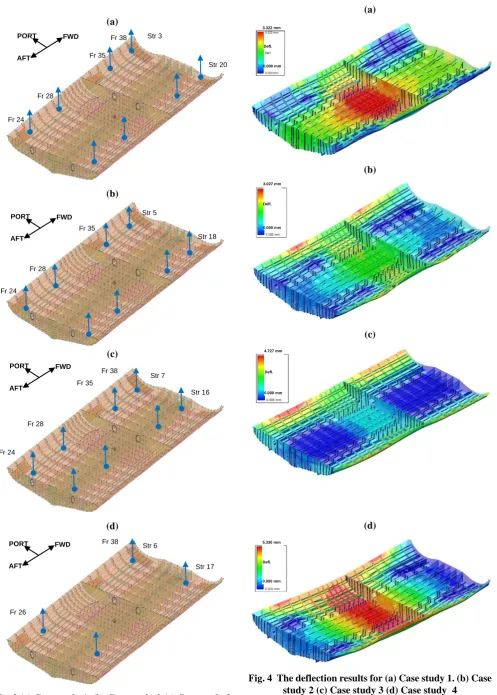
There are four cases of various lifting eye pads positions. The variations of the eye pads postiton are shown in Figure 3. In case 1 as shown in Figure 3 (a), there are 8 lifting eye pads were used. The lifting eye pads were positioned at frame number 24, 28, 35, and 38. Four of the lifting eye pads were positioned and aligned along stringer number 3 and another four eye pads were positioned and aligned along stringer number 20.
Fr 34 Fr 36
Fr 38 Fr 40
Fr 30
Fr 24
Fr 28 Fr 26
Fr 32
MWB495
MWB494 AFT
FWD
PORT Str1
Str22 Str11
International Journal of Innovative Technology and Exploring Engineering (IJITEE) ISSN: 2278-3075, Volume-8 Issue-12, October 2019
(a)
(b)
(c)
(d)
Fig. 3 (a) Case study 1. (b) Case study 2 (c) Case study 3 (d) Case study 4
(a)
(b)
(c)
[image:3.595.56.554.47.743.2](d)
Fig. 4 The deflection results for (a) Case study 1. (b) Case study 2 (c) Case study 3 (d) Case study 4
3.322 mm
0.000 mm Defl.
3.027 mm
Defl.
0.000 mm
Defl. 4.727 mm
0.000 mm
5.330 mm
Defl.
0.000 mm
Fr 24 Fr 28
Fr 35
AFT
FWD PORT
AFT
FWD PORT
AFT
FWD PORT
AFT
FWD PORT
Fr 24 Fr 28
Fr 35 Fr 38
Fr 24 Fr 28
Fr 35 Fr 38
Fr 26
Fr 38
Str 3
Str 20
Str 5
Str 18
Str 7
Str 16
Str 6
In case 2 as shown in Figure 3(b), there are 8 lifting eye pads fixed to the sub-block.
The eye pads were positioned at frame number 24, 28, 35, and 38. Four of the lifting eye pads were positioned and aligned along stringer number 5 and another four eye pads were positioned and aligned along stringer number 18. In case 3 as shown in Figure 3(c), there are 8 lifitng eye pads were used. The eye pads were positioned at frame number 24, 28, 35, and 38. Four of the lifting eye pads were positioned and aligned along stringer number 7 and another four eye pads were positioned and aligned along stringer number 16. In case 4 as shown in Figure 3(d), only 4 lifting eye pads were used. The eye pads were positioned at frame number 26, and 38. Two of the lifting eye pads were positioned and aligned along stringer number 6 and another two eye pads were positioned and aligned along stringer number 17.
III. SIMULATION IN MULTIFRAME
The simulation using Multiframe to simulate the responses in both longitudinal and transverse strength involved steps as the followings:
Construction of the model in Multiframe
The construction of the model consists of 22325 patches,
4722 members and 11655 of node as shown in Figure 3. The structure is divided into numerous imaginary elements either in triangular or rectangular shape, which meet up at nodes. All the elements need to be connected by nodes.
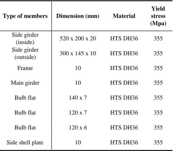
Assigning the structural members and the material All the structural members section in the sub-block need to be assigned before any simulation can be initiated. The structure sections need to be assigned as either „I‟ beam, bulb plate, plate etc. The individual structural member need are also to be assigned in terms of its dimensions i.e. height, length, thickness, radius of the bulb plate etc.
In Multiframe, the dimension can be easily be assigned using the built-in library with standard dimensions of the structural members as shown in Table 1. The material and the yield stress of the material of each section need to be assigned using the same interface in Multiframe. The material for all the structural members and plates are assigned as marine grade high tensile steel DH36, which is having a yield strength of 355Mpa.
[image:4.595.156.442.360.609.2]All the coordinate of the nodes need to be assigned, where all the nodes need to be connected properly. Stringers were added once all the frames were grouped.
Table. 1 Type of structural members with its dimensions and material selected using the library in Multiframe
Type of members Dimension (mm) Material
Yield stress (Mpa) Side girder
(inside) 520 x 200 x 20 HTS DH36 355
Side girder
(outside) 300 x 145 x 10 HTS DH36 355
Frame 10 HTS DH36 355
Main girder 10 HTS DH36 355
Bulb flat 140 x 7 HTS DH36 355
Bulb flat 120 x 7 HTS DH36 355
Bulb flat 120 x 6 HTS DH36 355
Side shell plate 10 HTS DH36 355
Structural constraints
All the lifting points in Case 1, 2, 3, and 4 were distributed evenly around the centre of gravity of the sub-block. As in case study 1, there are 8 points of load were used to simulate the lifting eye pads location during lifting. This 8 points of force would replicate a hanging sub-block during the lifting operation. These 8 points would act as the structural constraints. All these points need to be defined in Multiframe by selecting the points of the lifitng pads. By selecting the points, fixed constraint marks were assigned in Multiframe at all those points selected earlier.
Selection of boundary conditions
In the boundary conditions, the degree of freedom of all the
structural members need to be defined in order to make the sub-block behaving in a realistic way. In Multiframe, there are six degrees of freedom to be considered, 3 are the translations in the x, y and z axis namely as tx, ty, and tz
International Journal of Innovative Technology and Exploring Engineering (IJITEE) ISSN: 2278-3075, Volume-8 Issue-12, October 2019
Multiframe solving the displacement and forces
All the structural members i.e. frames, stringers were divided into numerous triangular elements. All these elements were connected by nodes in Multiframe. Then a displacement function was assigned in Multiframe to simulate the displacement at any point within the element at the nodes. Therefore strains and stresses can be determined from the displacement simulated. The forces at each node are equivalent to the boundary forces on the structural element under consideration. The displacement of one element must be compatible with those of adjacent elements. Finally, the whole array of the internal forces and applied external forces must be in equilibrium in order for the computation to converge. The simulations were typically completed in a few minutes of computation using a 4 cores 2.0 GHz processor.
IV. RESULTSANDDISCUSSIONS
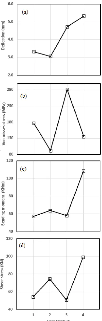
The results generated in Multiframe are deflection, von Mises stress, bending moment, and shear stress as presented in the sub-sections below.
Deflection
The highest deflection was found in case study 4 at 5.33mm, and the lowest deflection was found in case study 2 at 3.054mm, as shown in Figure 5 (a). It was observed that most of the maximum deflection occurred at the side shell which have no structural members, see Figure 4(b) and 4(c). However in case study 1 and 4, the maximum deflection was observed occurring at the bottom longitudinal frames in the vicinity of the centre of gravity, see Figure 4(a) and 4(c).
Generally the rules of the classification society do not concern on the deflection as long the structural members does not fail [7]. But in the shipbuilding process, this may be a source of concern, where typically for a long slender structure, the deflection may be relatively large that it may cause crack in the structural members or the adjacent members. Therefore some of the method that shipbuilders employed prior to the lifting operation in reducing deflection and stress is by adding supporting members such as brackets. These brackets helps in reducing the deflection and stress by absorbing and distributing all the forces onto the bracket itself.
Von Mises stress and assessment using DNV-GL rules The highest Von Mises stress was found in case study 3 at 281.91Mpa, and the lowest Von Mises stress was found in case study 2 at 90.84Mpa, as shown in Figure 5 (b). These results were assessed with the DNV-GL acceptance criteria which can be found in DNV-GL Rules for classification, Pt.3 Ch.7, Finite element analysis, Sec.3, Partial Ship Structural Analysis [8]. The acceptance criteria in the rules is in terms of the permissible coarse mesh yield utilization factors, λy perm. The permissible coarse mesh yield utilization factor is given as 0.80 in Table 1 for acceptance criteria 1 which can be applied to plating of all longitudinal hull girder structural members and primary supporting structural members and bulkheads.
The yield utilization factor, λy, should be lower than the permissible coarse mesh yield utilization factor. This yield
utilization for shell elements in general can be calculated using Equation 1:
y vm y
R
(Eqn. 1)where σvm is the von Mises stress obtained from the simulation in N/mm2, and Ry is the nominal yield stress taken to be equal to 235/k as shown in Equation 2.
k
R
y235
(Eqn. 2) [image:5.595.306.550.295.426.2]where k is the material factor, and for material DH36, the material factor can be taken as 0.72 as in Table 2 in DNV-GL rules Ch 3 Sec.1 [9]. Using Equation 1 and 2, the yield utilization factor can be calculated for all the case studies as shown in Table 2.
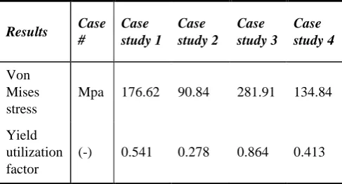
Table. 2 Yield utilization factor for all the case study. Case study 3 yield utilization factor was more than the
permissible coarse mesh utilization factor.
Results Case
#
Case study 1
Case study 2
Case study 3
Case study 4
Von Mises stress
Mpa 176.62 90.84 281.91 134.84
Yield utilization factor
(-) 0.541 0.278 0.864 0.413
The highest yield ulitilization factor was found in case study 3 at 0.864, where it did not comply with the permissible coarse mesh yield utilization factor which is limited to 0.80. The lowest yield utilization factor was found in case study 2 at 0.278, where it is approximately three times lower than the permissible yield utilization factor. Therefore it is concluded that case study 2 is the best configuration of lifting for this sub-block
Bending moment
The highest bending moment was found in case study 4 at 108.49kNm, and the lowest bending moment was found in case study 1 at 57.12kNm, as shown in Figure 5 (c). Most of the bending moment occurred at the eye pads location. The shell plate which were at the furthest from the eye pads location has the least bending moment.
Shear stress
Fig. 5 The results in terms of (a) Deflection in mm (b) von Mises stress in kN (c) Bending moment in kNm (d) Shear
stress in kN, with respect to the case studies.
V. CONCLUSION
A study on the structural behavior of a sub-block during lifting operation was presented. The study was done using
Multiframe’s finite element method. There are four cases of various lifting eye pads positions. The lifting eye pads were
varied in its location at different frame number and stringer number. The case studies were labeled as case study 1, 2, 3 and 4. The highest deflection was found in case study 4 at 5.33mm, and the lowest deflection was found in case study 2 at 3.054mm. It was observed that most of the maximum deflection occurred at the side shell which have no structural members. In case study 1 and 4, the maximum deflection was observed occurring at the bottom longitudinal frames in the vicinity of the centre of gravity. The highest bending moment was found in case study 4 at 108.49kNm, and the lowest bending moment was found in case study 1 at 57.12kNm. The highest shear stress was found in case study 4 at 99.17kN, and the lowest shear stress was found in case study 3 at 50.84kN. The highest Von Mises stress was found in case study 3 at 281.91Mpa, and the lowest Von Mises stress was found in case study 2 at 90.84Mpa. These results were assessed with the DNV-GL acceptance criteria which can be found in DNV-GL Rules for finite element analysis. The highest yield ulitilization factor was found in case study 3 at 0.864, where it did not comply with the permissible coarse mesh yield utilization factor which is limited to 0.80. The lowest yield utilization factor was found in case study 2 at 0.278, where it is approximately three times lower than the permissible yield utilization factor. Therefore using this acceptance criteria it is concluded that case study 2 is the best configuration in lifting the sub-block.
REFERENCES
1. R.L. Storch, Ship Production, 2nd Edition, Cornell Maritime Press, Centreville, Maryland, 1995.
2. D.J. Eyres and G.J. Bruce, Ship Construction, 7th Edition, Butterworth-Heinemann, 2012.
3. Bentley Systems, Multiframe Windows version 16 user manual, Bentley Systems Incorporated, USA, 2013.
4. M.N. Misbah, S.H.Sujiatanti, D. Setyawan, R.C. Ariesta, and S. Rahmandianto, Structural analysis on the block lifting in shipbuilding construction process, MATEC Web of Conferences, Volume 177, EDP Sciences, 2018
5. C. Liebert and M. Rashid, Finite element analysis of a lifting portable offshore unit – A comparison between a shell and a beam model, Master‟s Thesis, Department of Applied Mechanics, Chalmers University of Technology, Goteborg, Sweden, 2015.
6. R. Fernandez, I. Lazakis, G. Theotokatos, E. Boulougouris, “Tanker ship structural analysis for intact and damage cases,” International Conference on Maritime Safety and Operations, Glasgow, 13th -14th October, 2016, pp. 145–153.
7. DNV-GL, Rules for classification of ships, Part 3 Hull, Chapter 1 General principles, DNV-GL AS, 2015.
8. DNV-GL, Rules for classification of ships, Part 3 Hull, Chapter 7 Finite element analysis, DNV-GL AS, 2018.