Joint Multi-User Precoding in Multi-Relay Systems
Hang Long
1, Wei Xiang
2, Yueying Zhang
1, Jing Wang
1, and Wenbo Wang
11: Key Laboratory of Universal Wireless Communication, Ministry of Education
Beijing University of Posts & Telecommunications Beijing 100876 China
2: Faculty of Engineering and Surveying
University of Southern Queensland Toowoomba, QLD 4350, Australia
Abstract—Multi-user precoding in multi-relay systems is in-vestigated in this paper. Firstly, a distributed precoder through the relay nodes is presented, which performs as a sub-optimum solution in terms of both the outage probability and ergodic capacity. Then, a multi-user precoder at the source node is jointly designed, where is used to enhance the maximum signal-to-leakage-and-noise ratio of each data stream.
I. INTRODUCTION
The relay technique has attracted significant attention in both academia and industry areas. Meanwhile, the multi-user (MU)-multi-input-multi-output (MIMO) system is an impor-tant research area that allows for spatial division multi-access and multi-user diversity. If only one relay node with multiple antennas is used between the source node and multiple users, the relay system can be treated as a simple concatenation of a single-user MIMO system (the source-relay link) and a MU-MIMO system (the relay-users links), where precoding schemes in conventional MIMO systems can be directly used [1], [2]. If multiple relay nodes are located between the source node and users, coherent combination of signals from multiple relay nodes and inter-stream interference (ISI) mitigation techniques are both required for the precoding design.
Similar to the work on conventional MU-MIMO systems, the downlink multi-user multi-relay systems [3] - [8] are much more popular than their uplink counterparts [9]. Precoding can be utilized at the source node to mitigate ISI [6] - [8]. On the other hand, if multiple relay nodes transmit to the users simultaneously, a distributed precoder can be used through these relay nodes. The two precoders in the downlink multi-user multi-relay system can be designed either independently or jointly.
The decode-and-forward protocol in [3] - [6] divides the entire source-relay-destination transmission into two indepen-dent parts. Additionally, the entire transmission is carried out in three phases as shown in [3] - [6], which is inefficient. Hence, precoding design for two-phase relaying protocols [7] - [9] is more attractive.
In [7], a single antenna is assumed for relay and destination nodes, where multi-user precoding at the source node and distributed precoding through relay nodes are employed. The
0This research was supported by the National Science Foundation for
Post-doctoral Scientists of China under Grant 20110490329 and National Key Technology R&D Program of China under Grant 2010ZX03005-001-03.
transmit powers of the source and relay nodes are used as the optimization objective functions. However, the scheme in [7], [9] is so complicated that there is no closed-form expression for the precoder, and iterative algorithms are adopted. Similar problem exists in the design in [8], where a separate transmit power constraint for each relay node is also assumed.
With the amplify-and-forward (AF) relaying protocol, the multi-user precoder at the source node and the distributed precoder through relay nodes impact on each other. In this paper, the distributed precoder through relay nodes are de-signed independently at first. Considering the trade-off among multiple users, a hybrid signal-to-interference-and-noise ratio (SINR) is defined as the optimization objective function for the distributed precoder design. Then, joint precoder design of the two precoders is investigated. Users are adaptively divided into two groups. The precoding vectors at the source node of the first group are used to maximize the maximum
signal-to-leakage-and-noise ratio (SLNR) which is defined according to the equivalent channels through relay nodes for the distributed precoder design. The precoding vectors of the second group are designed to change the equivalent channels, so that the distributed precoder can improve on the SINR of each destination node simultaneously.
II. SYSTEMMODEL ANDLINEARTWO-PHASERELAYING PROTOCOL
Notations:
AT, A∗,AH, A−1 andkAk
F denote the transpose, con-jugation, conjugate-transpose, pseudoinverse and Frobenius norm of matrixA, respectively. A(i, j) is the element in the
ith row and thejth column ofA.A(i,:)andA(:, i)denote the
ith row and theith column ofA, respectively.Inis then×n identity matrix. 0m,n is the m×n all-zero matrix. diag(a) is the n×n diagonal matrix with a as its diagonal whena
is an n×1 or 1 ×n vector. E(·) represents mathematical expectation. Pr(·) is used as the probability notation. bxc is the largest integer which is not larger thanx.
S
. .
. ..
.
R
N
R 1
R
1
D
D
N
D
H
G
. . .
Phase I Phase II
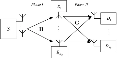
Fig. 1. System model of the multi-user multi-relay system.
destination nodes are not considered in this study. Without explicit explanation, i is used as the index of a relay node (i∈ {1,2,· · ·, NR}), andjis used as the index of a destination node (j∈ {1,2,· · ·, ND}) in the following.
InPhase I, the transmit signal ofSisxS ∈CNS×1with the power constraint of E(xH
SxS) =ES, and the received signal at Ri isyRi. The received signals atNR relay nodes can be written in vector form
yR1 .. .
yRNR
| {z }
yR
=
h1,1 · · · h1,NS ..
. . .. ...
hNR,1 · · · hNR,NS
| {z }
H
xS+
nR1 .. .
nRNR
| {z }
nR .
(1) In Phase II, the relaying signal ofRi isxRi, and the received signal at Dj is yDj. Similarly, the received signals at ND destination nodes can also be written in vector form
yD1 .. .
yDND
| {z }
yD
=
g1,1 · · · g1,NR ..
. . .. ...
gND,1 · · · gND,NR
| {z }
G
xR1 .. .
xRNR
| {z }
xR
+
nD1 .. .
nDND
| {z }
nD .
(2) In (1) and (2), i∈ {1,2,· · · , NR}, j∈ {1,2,· · · , ND}, and
k∈ {1,2,· · ·, NS}. In addition,
• hi,k is the channel gain from thekth antenna ofStoRi; • gj,iis the channel gain from Ri toDj;
• nRi andnDj denote the additive white Gaussian noise at Ri andDj, respectively, i.e.,nRi, nDj∼ CN(0, σ2). Noted that the two-phase relaying protocol assumed in this study is different from those in [3] - [6]. In Phase I, the transmit signal ofS can be rewritten as
xS =Fd (3)
whered∈CND×1 is the data vector before precoding, andF is the precoding matrix at S. It is assumed that only one data stream is sent to each destination node, so that E(ddH) =
IND. F is constrained as kFk 2
F = ES to satisfy the power constraint of S. It is assumed thatNS≥ND andNR≥ND. In Phase II, the transmit signal of Ri can be written as a linear function of the received signal
xRi =βiyRi (4)
withβibeing the relaying coefficient ofRi. We can divideβi into two parts as follows
βi=piαi (5)
where αi is the power normalization coefficient with
α2 iE[|yRi|
2] = 1. Integrating (3) into (1) gives rise to
α−2i =E[|yRi|
2] =kH(i,:)Fk2
F +σ2, i∈ {1,2,· · · , NR}. (6) In (5), pi is the distributed precoding element of Ri. The distributed precoding elements of the NR relay nodes consti-tute the distributed precoding vectorp= [p1, p2,· · ·, pNR]
T.
The relaying signal vectorxR can also be written as a linear function of yR
xR=ByR (7)
where
B= diag(a)diag(p) (8)
is the diagonal relaying matrix, and
a= [α1, α2,· · ·, αNR]
T (9)
is the normalization vector.
Integrating (1), (3) and (7) into (2) gives
yD=GBHFd+GBnR+nD. (10)
We can define the equivalent channel matrix as
H(e)=GBHF. (11)
The diagonal elements of H(e) are the equivalent channels of the target signals at the destination nodes, whereas the other elements of H(e) represent ISI. Therefore, ISI cannot be suppressed at the receiver since only a single antenna is equipped at each destination node.
The covariance matrix of the equivalent noise is defined as
Rn=E[(GBnR+nD)(GBnR+nD)H]
= (GBBHGH+I
ND)σ
2. (12)
According to (10)-(12), the received SINR at Dj can be calculated as
γj =
¯
¯H(e)(j, j)¯¯2 °
°H(e)(j,:)°°2 F−
¯
¯H(e)(j, j)¯¯2+R n(j, j)
(13)
wherej∈ {1,2,· · ·, ND}.
[image:2.612.57.291.54.169.2]III. DISTRIBUTEDPRECODING THROUGHRELAYNODES
In this section, distributed precoding design is studied without considering the multi-user precoding matrix F, i.e.,
NS = ND, and F = IND. Under this assumption, the dis-tributed precoder phas two effects: 1) coherent combination of signals from NR relay nodes at each destination node; 2) ISI mitigation. Additionally, the trade-off among the ND destination nodes should also be considered in the distributed precoder design.
The normalized channel matrix of Phase II is defined as
Ga =Gdiag(a). (14)
The equivalent channel vector of target signal dj from S to
Dj through NR relay nodes is defined as
ej= diag [Ga(j,:)]H(:, j), j∈ {1,2,· · · , ND}. (15)
Correspondingly, the power of the received target signal at
Dj is |H(e)(j, j)|2 =pTejeHj p∗. Likewise, the interference channel vector ofdk atDj (k6=j) is defined as
ckj= diag [Ga(j,:)]H(:, k), j, k∈ {1,2,· · · , ND}. (16)
|H(e)(j, k)|2 = pTc
kjcHkjp∗ is the received interference power at Dj fromdk, i.e., the data stream for thekth user.
The received relaying noise power at Dj is pTRDjp ∗σ2, in which
RDj = diag
n
[|Ga(j,1)|2,|Ga(j,2)|2,· · · ,|Ga(j, NR)|2] o
.
(17) The received SINR ofDj in (13) is rewritten as a function of
p
γj=
pTe jeHj p∗
pT "
P
k,k6=j
(ckjcHkj) +RDjσ2
#
p∗+σ2
. (18)
In this section, the total power of NR relay nodes is constrained as E(xH
RxR) = ER, which is different from the assumption in [8]. Since αi is used to normalize the power of the received signal at each relay node, the total power constraint of the relay nodes is equivalent to the Frobenius norm of the precoding vector p
kpk2
F =pTINRp ∗=E
R. (19)
According to (19), the last term in the denominator of (18) can be rewritten asσ2=pT(σ2/E
RINR)p∗. As a result, (18) is rewritten as
γj =
pTe jeHj p∗
pTC jp∗
(20)
where
Cj= X
k,k6=j
ckjcHkj+ µ
RDj+
1
ERINR 
σ2. (21)
The optimization objective function is fairly important in the precoder design. Objective functions in relation to system capacity and reliability are usually adopted, e.g.,
pMC = arg max
kpk2 F=ER
ND
X
j=1
log2(1 +γj) (22)
and
pMM= arg max
kpk2 F=ER
µ
min
1≤j≤ND γj
. (23)
The precoder design in (22) can achieve the maximum system capacity performance, whereas the one in (23) with maximiz-ing the minimum SINR is usually employed for the system reliability performance improvement.
Generally speaking, system capacity and reliability are two conflicting design criteria in multi-user systems. A precoder design cannot perform well in both criteria. A trade-off between reliability and capacity performance needs to be considered. Also, the trade-off among the ND users should be taken into account. Therefore, a hybrid SINR is proposed as follows
γE = p TEp∗
pTCp∗ (24)
where
E=
ND
X
j=1
(ejeHj ),C=
ND
X
j=1
Cj. (25)
The numerator ofγE is the sum of the numerators of γj, j∈
{1,2,· · ·, ND}, whose denominators are added to become the denominator ofγE. The precoder is achieved as follows
pH= arg max
kpk2 F=ER
γE. (26)
The received powers of the ND users are equally combined in the expression of γE, whereas the interference covariance matrices are also simply summed up as shown in (24) and (25). In the future work, different user weights can be introduced into the expression of γE.
E and C are two Hermitian matrices as can be seen from (25). The optimization problem in (26) can be solved as a classical eigenvalue problem [10], [11]. The eigenvalue decomposition ofC is shown as
C=UCDCUHC (27)
whereUC is constructed of the eigenvectors of C, and DC is a diagonal matrix with descendingly sorted eigenvalues. An assistant matrixQis defined as
Q=
³
UCD− 1 2 C
´H
E
³
UCD− 1 2 C
´
. (28)
The range of γE is determined by the eigenvalues ofQ
λQ,min≤γE = p TEp∗
where λQ,min and λQ,max are the minimum and maximum eigenvalues of Q, respectively. The precoder that maximizes
γE can be written as
pH= arg max
kpk2 F=ER
γE=µU∗CD −1/2
C [UQ(:,1)]∗ (30) where µ is the normalization coefficient satisfying
kpHk2F =ER, and UQ(:,1) is the eigenvector of Q relative to λQ,max.
Usually, the optimization problems defined in (22) and (23) cannot be solved exactly, and there is no closed-form expression for the precoders. Some iterative methods can be employed, but the complexity is remarkably higher compared with the solution in (30).
Simulation results in Section V demonstrate that the pro-posed distributed precoder apparently outperforms the fixed AF protocol. Compared with the precoders optimizing the system capacity or reliability in (22) and (23), the proposed distributed precoder in (30) has a closed-form expression and is able to provide performance close to optimum in terms of both outage probability and ergodic capacity. The proposed distributed precoder is a design trade-off between the system capacity and reliability in the multi-user system.
IV. JOINTPRECODINGDESIGN
In Section III, the design of p is presented without the consideration ofFatS. However, replacingHwithHF, the design in (30) can also be used. The design ofFin cooperation withpis considered in this section.
A. SLNR Maximization
If the distributed precoding vector is constrained bykpk2 F =
1, the maximum received target signal power atDj iskejk2F whenp=e∗
j/kejkF. Similarly, the equivalent channel vector of the interference from dj to Dk iscjk,j 6=k as shown in (16). This also implies that the maximum received interference power atDk fromdj iskcjkk2F (p=c∗jk/kcjkkF). Therefore, the maximumSLNR of thejth data stream can be defined as
γM,j=
ERkejk2F
ER P
k,k6=j
kcjkk2F+σ2
(31)
where the “P” term in the denominator is the interference power experienced at other destination nodes leaking from
dj. The definition in (31) is based on the maximum received signal and maximum interference power as mentioned above. Therefore, it is termed themaximum SLNR.
The maximum SLNR defined in (31) can be written as a function of the precoding vectorfj =F(:, j). It is required that
kFk2
F =ES due to the power constraint ofS. In addition, it is assumed that the columns of F(fj) have the same Frobenius norm, i.e.,kfjk2F =ES/ND.
Considering multi-user precoding atS, (15) can be rewritten as
ej =HG,jfj (32)
where
HG,j = diag [Ga(j,:)]H. (33)
Similarly,
cjk=HG,kfj. (34)
According to the Frobenious norm constraint of the precoding vectors, the noise power in the denominator of (31) can be replaced withfH
j (ND/ES·σ2·INS)fj. ThemaximumSLNR is thus rewritten as
γM,j =
fH
j HHG,jHG,jfj P
k,k6=j
fH
j HHG,kHG,kfj+σ2
= f
H
j HHG,jHG,jfj
fH j
" P
k,k6=j ³
HH G,kHG,k
´
+NDσ2
ES INS
#
fj
.(35)
Note that ej andcjk are quite similar as can be observed in (32) and (34). The difference lies in the corresponding rows ofGa. The multi-user precoding design atS should take the interference signal power into account. If each precoding vector is designed to maximize the target signal power, the interference power will also be enhanced due to the similarity between ej and cjk. The maximum SLNR defined in (31) includes the target signal and leakage interference powers. Furthermore, the precoding design is easier since γM,j is a function of fj and independent of the other columns ofF.
The fraction expression of (35) is similar to (24), so that the classical solution in (28)-(30) can be extended to achieve the initial multi-user precoding vectors as follows
fj = arg max
fj
γM,j =µUCLD −1/2
CL UQL(:,1) (36)
wherej ∈ {1,2,· · · , ND},µis the normalization coefficient,
UCL andDCL can be obtained by the eigenvalue decompo-sition ofCL
CL= X
k,k6=j ¡
HH G,kHG,k
¢
+NDσ
2
ES INS =UCLDCLU H CL,
(37) andUQL(:,1) is the eigenvector of the largest eigenvalue of QL
QL= ³
UCLD −1
2 CL
´H
HH G,jHG,j
³
UCLD −1
2 CL
´
. (38)
B. Channel Similarity
of all the users. If the equivalent target signal channels of several users are similar, e.g., the angle between any two channel vectors is close to0, i.e.,
¯ ¯eH
j ek ¯ ¯
kejkFkekkF
→1, j6=k, (39)
pH can approximately maximize the received SINRs at all the destination nodes. The similarity among the equivalent channels can be used to improve on system performance.
On the other hand, the equivalent channels are affected by
F. Therefore, we can divide theNDusers into two groups, i.e., the interference mitigation group and channel similarity group. The precoding vectors atSof the interference mitigation group are designed to maximize the maximum SLNR as described in (36)-(38). The ones of the channel similarity group are designed to guarantee the channel similarity among all the equivalent channels. It is intuitive that the performance of the users in the first group are worse than that of those in the second group if random grouping or fixed group division is used. Adaptive group division should be adopted. The users with better channel qualities are selected into the interference mitigation group.
The initial multi-user precoding matrix F is calculated to maximize the maximumSLNR. Then the equivalent channels
ej, j∈ {1,2,· · ·, ND}are calculated using (32). The Frobe-nius norms of all the equivalent channels are calculated and sorted, and the first bND/2cusers with the largest Frobenius norms are chosen into the interference mitigation group. It can be assumed without loss of generality that the 1st
-bND/2cth users are chosen. Then, the precoding vectors of the channel similarity group (fj,bND/2c+ 1≤j≤ND) are designed to guarantee the similarity between e1 ∼ ebND/2c and ebND/2c+1 ∼eND. Each precoding vector is calculated independently as follows
fj = arg max
kfjk2F=ES/ND bNXD/2c
k=1 ¯ ¯eH
j ek ¯ ¯2
= µHHG,jUEbND/2c(:,1). (40)
whereUEbND/2c(:,1) is the eigenvector of the largest
eigen-value ofEbND/2c
EbND/2c= bNXD/2c
j=1
ejeHj =UEbND/2cDEbND/2cU
H EbND/2c.
(41) The relationship between the two groups can be seen clearly from a special case of ND = 2. Equation (40) can be simplified as
f2=µHHG,2HG,1f1. (42)
That is, the equivalent channels of the two users are the same without considering the Frobenious norm. With adaptive grouping, the performance of all the users are identical.
-5 0 5 10 15 20
0.01 0.1 1
p
AF
p
H
p
MM
p
MC
N
S
= N
R
= N
D
= 2
th
= -3 dB,
SR
= 15 dB
RD
(dB)
p
o
u
t
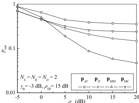
Fig. 2. Distributed precoding through relay nodes: outage probability.
V. NUMERICAL ANDSIMULATIONRESULTS Independent and identically distributed Rayleigh fading channels are assumed, i.e.,H(i, k)∼ CN(0, σ2
SR), G(j, i)∼
CN(0, σ2
RD), k ∈ {1,2,· · ·, NS}, i∈ {1,2,· · ·, NR}, and
j ∈ {1,2,· · · , ND}. ES = ND, ER = 1, σ2 = 1. The average signal-to-noise ratios (SNRs) of the two phases are defined asρSR=ESσSR2 /σ2, ρRD=ERσRD2 /σ2.
Two evaluation metrics are considered, i.e., the ergodic capacity
C=
ND
X
j=1
log2(1 +γj), (43)
and the outage probability
pout= 1
ND ND
X
j=1
Pr(γj < γth) (44)
whereγth is the SNR threshold.
Firstly, distributed precoding through NR relay nodes is evaluated as shown in Figs. 2 and 3. The three precoders described in Section III [(30), (22) and (23)] are compared. Moreover, the simple AF relaying scheme without adaptation
pAF = p
ER/NR[1,1,· · · ,1]T is also used as a compari-son. The two precoders in (22) and (23) are achieved with exhaustive search through the unitary space.
As shown in Fig. 2, the outage probability curves of the four precoders exhibit the so-called “floor”, since ISI cannot be completely eliminated with a small number of relay nodes. It is intuitive that pMM in (23) is best if ρRD is large enough.pH performs close to pMMand outperforms it when
[image:5.612.327.551.54.220.2]ρRD < 1 dB. With pAF, signals from relay nodes are randomly combined at each destination node, so that pAF gives the worst performance.
0 5 10 15 20 25 1
2 3 4 5
E
r
g
o
d
i
c
c
a
p
a
c
i
t
y
(
b
i
t
/
c
h
a
n
n
e
l
u
s
e
)
RD
(dB) p
AF
p
H
p
MM
p
MC
SR
= 10 dB
SR
= 15 dB
N
S
= N
R
= N
D
= 2
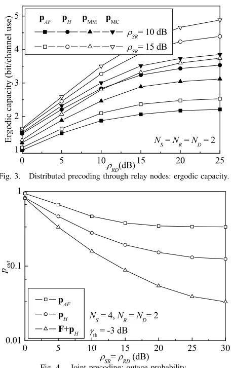
Fig. 3. Distributed precoding through relay nodes: ergodic capacity.
0 5 10 15 20 25 30
0.01 0.1 1
N
S
= 4, N
R
= N
D
= 2
th
= -3 dB
SR
=
RD
(dB)
p
o
u
t
p
AF
p
H
F+p
H
Fig. 4. Joint precoding: outage probability.
and capacity. Additionally, pH has a closed-form expression as shown in (30), which is an evident advantage and different from the designs in (22) and (23).
Then, the joint design of multi-user precoding at S and distributed precoding through NR relay nodes in Section IV is evaluated in Figs. 4 and 5. The fixed distributed precoding vector pAF is also used as a comparison. The legend “pH” in the two figures denotes the distributed precoding vector in (30). If the distributed precoder is used without the cooperation of the multi-user precoder at S, ND antennas at S are randomly selected for transmission, which is equivalent to
F = [IND,0ND,NS−ND]
T. Fig. 4 gives the outage proba-bility performance of distributed precoding as well as joint precoding. The distributed precoderpH outperforms the fixed precoderpAF, and the cooperation of the multi-user precoding matrix F further improves on the system reliability. Similar conclusions can be drawn from Fig. 5. The advantage of joint precoding in Section IV is very apparent at high SNRs (ρSR=ρRD>15 dB).
VI. CONCLUSION
Multi-user precoders, i.e., the multi-user precoder at the source node and the distributed precoder through relay nodes, in the multi-relay system is investigated. The trade-off among
0 5 10 15 20 25 30
0 1 2 3 4 5 6 7 8
N
S
= 4, N
R
= N
D
= 2
E
r
g
o
d
i
c
c
a
p
a
c
i
t
y
(
b
i
t
/
c
h
a
n
n
e
l
u
s
e
)
SR
=
RD
(dB) p
AF
p
H
F+p
H
Fig. 5. Joint precoding: ergodic capacity.
multiple users is considered in the precoding design, as well as the trade-off between system reliability and capacity. A hybrid SINR is defined and the closed-form expression for the distributed precoder is derived. Then, we investigate the joint design of the two precoders. The users are adaptively divided into two groups. The precoding vectors of the first group are designed to enhance the received signal power and mitigate the leakage interference to other users. The precoding vectors of the second group are designed to guarantee that the distributed precoding vector can enhance the SINR of each user simultaneously. The joint precoding is preferred for the high SNR region when a large number of antennas are equipped at the source node.
REFERENCES
[1] C. B. Chae, T. Tang, R.W. Heath Jr., and S. Cho, “MIMO relaying with linear processing for multiuser transmission in fixed relay networks,”
IEEE Trans. Signal Processing, vol. 56, no. 2, pp. 727-738, Feb. 2008. [2] R. Zhang, C.C. Chai, and Y.C. Liang, “Joint beamforming and power control for multiantenna relay broadcast channel with QoS constraints,”
IEEE Trans. Signal Processing, vol. 57, no. 2, pp. 726-737, Feb. 2009. [3] N. Devroye, N.B. Mehta, and A.F. Molisch, “Asymmetric cooperation among relays with linear precoding,” in Proc. IEEE Globecom 2007, Washington DC., Nov. 2007, pp. 4391-4396.
[4] G. Atia and A.F. Molisch, “Cooperative relaying with imperfect channel state information,” inProc. IEEE Globecom 2008, New Orleans, Nov. 2008, pp. 1-6.
[5] N. Devroye, N.B. Mehta, and A.F. Molisch, “Asymmetric cooperation among wireless relays with linear precoding,” IEEE Trans. Wireless Communications, vol. 7, no. 12, part 2, pp. 5420-5430, Dec. 2008. [6] J. Zhao, M. Kuhn, A. Wittneben, and G. Bauch, “Cooperative
transmis-sion schemes for decode-and-forward relaying,” inProc. IEEE PIMRC 2007, Athens, Greece, Sept. 2007, pp. 1-5.
[7] Y. Zheng and S. Blostein, “Downlink distributed beamforming through relay networks,” inProc. IEEE Globecom 2009, Honolulu, Hawaii, USA, Dec. 2009, pp. 1-6.
[8] H. Long, F. Wang, Y. Zhang, K. Zheng, and W. Wang, “Successive phase sharing and distributed multi-user precoding in multi-relay systems,”
IEEE Signal Processing Letters, vol. 17, no. 10, pp. 859-862, Oct. 2010. [9] Y. Zheng and S. Blostein, “Optimization of power constrained multi-source uplink relay networks,” inProc. IEEE Globecom 2009, Honolulu, Hawaii, Dec. 2009, pp. 1-6.
[10] K.K. Wong, R.D. Murch, and K.B. Letaief, “Performance enhancement of multiuser MIMO wireless communication systems,” IEEE Trans. Comms., vol. 50, no. 12, pp. 1960-1970, 2002.
[11] K.K. Wong, R.D. Murch, and K.B. Letaief, “Orthogonal space division multiplexing through joint use of multi-user MIMO smart antennas,” in
[image:6.612.62.290.49.412.2]