Int. J. Electrochem. Sci., 12 (2017) 6137 – 6155, doi: 10.20964/2017.07.85
International Journal of
ELECTROCHEMICAL
SCIENCE
www.electrochemsci.orgThe Corrosion Inhibition Effect of Pyrrole Derivatives on
Carbon Steel in 1.0 M HCl
H.S.Gadow1,*, H. M. Dardeer 2 1
Higher Institute for Engineering and Technology, New Demietta. 2
Chemistry Department, Faculty of Science, South Valley University, Qena, Egypt *
E-mail:hsgado73@gmail.com
Received: 27 March 2017 / Accepted: 14 May 2017 / Published: 12 June 2017
The inhibition effect of new pyrrole derivatives , namely, 13-((4-aminophenyl)sulfonyl)-10,11-dihydro-9H-9,10-[3,4]epipyrrolo anthracene-12,14(13H,15H)-dione (1), anthracen-9(10H)-ylidenehydrazine(2),(11S,15R)-13-(anthracen-9(10)-ylideneamino)10,11-dihydro-9H-9,10
[3,4]epipyrroloanthracene-12,14-(13H,15H)-dione (3) , 1,6-bis-(N -hexachloro-5-norbornene-2,3-dicarboximidyl) hexane (4) and N-Phenylsulfonyloxy-hexachloro-5-norbornene-2,3-dicarboximide (5), against the corrosion of carbon steel in 1.0 M HCl solution has been systematically studied by electrochemical measurements (potentiodynamic polarization measurements –impedance spectroscopy-electrochemical frequency modulation). The results of Potentiodynamic polarization indicate that all pyrrole derivatives are Mixed type inhibitors . Among the studied compounds, exhibited the best inhibition activity of 82.8% at 21x10-6M from compound (1). The chemical structure of the synthesized compounds was established by proton and carbon thirteen nuclear magnetic resonance (1H-NMR),(13C-NMR), Fourier transform infrared (FTIR)and mass spectroscopy.Solution analysis (UV–visible spectrophotometric method- Fourier transform infrared [FTIR]) support the above inferences.
Keywords: carbon steel; corrosion inhibition; pyrrole derivatives; HCl; EFM; FTIR
1. INTRODUCTION
equipment, chemical processing, transportation, pipelines, mining and construction. The alloys of iron as construction materials in industrial sectors has become a great challenge for corrosion engineers or scientists nowadays [1]. Corrosion inhibitors consider very important for protecting many metals and alloys. This leads to study the use of organic compounds as corrosion inhibitors. Adsorption of organic molecules on the surface of metals depend on their molecular structures, surface charge density [2,3]. Most of the organic compounds containing nitrogen, sulphur, oxygen with aromatic and heterocyclic rings through which they are adsorbed on the metal surface have been reported to be effective inhibitors for the corrosion of steel in acid media [4-8]. The choice of appropriate inhibitors depends on the type and the concentration of acid, temperature, the presence of dissolved organic and/or inorganic substances even in minor amounts and on the type of metallic material which protected [9]. Pyrrole and its derivatives are present in nature. Pyrrole derivatives have different applications in medicinally active compounds containing cholesterol reducing agent, antifungicides, antibiotics[10]. Also pyrrole derivatives use as solvent for resin [11] , lumine scence chemistry[12], catalyst for polymerization process[13], synthesis of alkaloids[14] and corrosion inhibitor[15,16] .
The aim of this paper is to synthesis of new pyrrole derivatives and explore, for the first time, the use of pyrrole derivatives as corrosion inhibitors for carbon steel in 1.0 M HCl medium. The choice of these compounds was based on the consideration that these organic compounds contain many π-electrons and hetero atoms like nitrogen, sulphur and oxygen atoms which induce greater adsorption on the steel surface compared with other organic inhibitors. The corrosion inhibitive activity of these organic compounds was examined successively via potentiodynamic polarization curves, electrochemical impedance spectroscopy (EIS), electrochemical frequency modulation (EFM ), isotherm calculations, FT-IR and UV spectroscopy techniques.
2. EXPERIMENTAL
2.1 Materials
2.1.1 Electrode and solutions.
For electrochemical studies, the working electrode was cut from a carbon steel sheet its composition by (weight%) is 0.200 C, 0.350 Mn, 0.024 P, 0.003 Si and the balance Fe. The dimensions of the working electrode were 20 x20 x1 mm, and The exposed area of the electrode was abraded by different grades of emery papers (grades 320- 1200), then rinsed and dried according to the standard methods[17].The corrosive medium (1.0 M HCl) was prepared from 37% hydrochloric acid (Merck) analytical grade chemical and double-distilled water.
2.1.2 Synthesis of inhibitors.
purification. The reactions were monitored by thin layer chromatography (TLC) using silica gel G (Spectrochem Pvt. Ltd., Mumbai). Each new compounds were fully characterized by FT/IR-4100 type A Serial Number B117761016. Mass spectrometry (HP Model, MS 5988 and AmD 402/3, EI 70 ev), in addition to 1H-NMR recorded on Bruker Avance П 400 NMR Spectrophotometer using DMSO and CDCl3 as solvent ,Chemical shifts are relative to TMS as internal reference.
Synthesis of 13-((4-aminophenyl)sulfonyl)-10,11-dihydro-9H-9,10-[3,4]epipyrroloanthracene- 12,14(13H,15H)-dione (1).
(11S,15R)-9,10,11,15-tetrahydro-9,10-[3,4]furanoanthracene-12,14-dione (0.5 gm, 1.81 mmole) and sulfanilamide (0.31 gm, 1.81 mmole) was heated under reflux in DMF (10 ml) for 5 hrs. The reaction mixture was poured onto water, the solid formed was filtered off, then dried and crystallized from benzene to give 13-((4-aminophenyl)sulfonyl)-10,11-dihydro-9H-9,10-[3,4]epipyrroloanthracene-12,14 (13H,15H)-dione (0.68 gm, 1.58 mmole) (1) as white crystals and obtained in 85 % yield: mp: 306 0C; IR (KBr, cm-1): indicates characteristic bands due to (NH2) at 3342, 3259 cm-1; (C-H aromatic) at 2969 cm-1 ; (C=O's) in the region 1776-1650 cm-1; (C=C aromatic) at1610 cm-1; (C-N) at 1317 cm-1 ; 1H-NMR (400 MHz/DMSO) δ (ppm): 3.46 (s, 2H, 2CH sp3); 4.89 (s, 2H, 2CH sp3); 6.68-7.81 (m, 12H, arom.H+2H, NH2); MS (EI, m/z): 430M+ corresponding to molecular formula (C24H18N2O4S). EA (%C, %H, %N,%S): Calc.: 66.99,4.18 ,6.51 ,7.45, Found, 66.96,4.21 ,6.48, 7.42.
Synthesis of anthracen-9(10H)-ylidenehydrazine (2).
A suspension of anthrone (0.5 gm., 2.6 mmol.) and hydrazine hydrate (3 mmol.) in toluene was refluxed for 6 hrs. After cooling; The precipitate formed was filtered off, dried and recrystallized from ethanol to give anthracen-9(10H)-ylidenehydrazine (0.42gm, 2.02 mmol.) as pale yellow crystals and obtained in 77.8% yield; m.p.240-242 °C; FT-IR (KBr, cm-1): showed the presence of bands due to(NH2) at 3345,3259 cm-1; (C-H aromatic) at 3080 cm-1 ; (C-H aliphatic) at 2900 cm-1 ; (C=N) at 1704 cm-1; 1H-NMR (300 MHz/CDCl3) indicated at δ 3.29 (s, 2H, CH2); 4.79(s, 2H, NH2); 7.12-8.34 (m, 8H, arom. H); MS (m/z): 208M+ corresponding to molecular formula (C14H12N2); EA (%C, %H, %N); Calc.: 80.77, 5.77 ,13.46 ; Found, 80.75, 5.79,13.43.
Synthesis of (11S,15R)-13-(anthracen-9(10)-ylideneamino)10,11-dihydro-9H-9,10-[3,4] epipyrrolo- anthracene-12,14-(13H,15H)-dione(3).
due to(C-H aromatic) at 3262 cm-1 ; (C-H aliphatic) at 2923 cm-1 ;(C=O’s) in the region 1776-1700 cm-1; (C=N) at 1620 cm-1; 1H-NMR (400 MHz/DMSO) indicated at δ 3.44 (s,2H,CH2); 3.65 (s, 2H, 2CH sp3); 4.87 (s, 2H, 2CH sp3); 6.66-7.79 (m, 16H, arom. H); MS (m/z): 466M+ corresponding to molecular formula (C32H22N2O2). EA (%C, %H, %N); Calc.: 82.40, 4.72 , 6.01 ; Found, 82.38, 4.75, 6.08.
Synthesis of 1,6-bis-(N -hexachloro-5-norbornene-2,3-dicarboximidyl) hexane (4).
A mixture of hexachloro-5-norbornene-2,3-dicarboxylic anhydride (0.5 gm, 1.35 mmole) was heated under reflux in toluene (20 ml) with hexamethylenediamine (1.35 mmole) for 4 hrs. After cooling the solid formed was collected and crystallized from benzene to give compound (4) (0.88 gm, 1.07 mmole) as white crystals and obtained in 80% yield: mp: 282-4 0C; IR (KBr, cm-1): indicated the presence of bands due to (CH2) aliphatic at 2861 cm-1 and two bands for (C=O's) in the region 1781-1700 cm-1 ; (C=C aromatic) at 1598 cm-1 ; (C-N aliphatic) at 1155 cm-1 ; 1H-NMR (400 MHz/DMSO) δ (ppm): 1.25 (m, 4H, 2CH2); 1.38(m, 4H, 2CH2); 3.32 (t, 4H, CH2); 4.08 (s, 4H, 4CH sp3); MS (EI, m/z): 822M+corresponding to molecular formula (C24H16N2O4Cl12); EA (%C, %H, %N, Cl%): Calc.:75.07,1.96,3.41,51.76, Found, 75.04,1.94,3.38,51.73
Synthesis of N-Phenylsulfonyloxy hexachloro-5-norbornene-2,3 dicarboximide (5).
An equimolar amount of N-hydroxy-hexachloro-5-norbornene-2,3-dicarboximide (1 gm, 2.59 mmole) and benzenesulfonyl chloride (2.95 mmole) were stirring in pyridine for 2 hrs.) . The solid formed was acidified with cold dilute HCl (1:1), the solid formed was filtered and dried. The target product (5) was crystallized from ethanol to give white crystals. (1.23 gm, 2.34 mmole) and obtained in 90.4% yield: mp: 282-4 0C; IR (KBr, cm-1): revealed the presence of band due to(C-H aromatic) at 3100 cm-1 and showed band for (C=O's) at 1754 cm-1and two bands for (SO2-O-) at 1397,1195 cm -1
; 1H-NMR (400 MHz/DMSO) δ (ppm): 4.28 (s, 2H); 7.75-8.04 (m, 5H,arom. H); 13C-NMR(400 MHz/DMSO) δ (ppm): 49.66( sp3-C-9); 50.11 (sp3-C-14); 79.01(sp3-C-10); 79.26 (sp3 –C-13); 104.28 (sp3-C-15);125.96 (Ar-C-4);128.84 (Ar-C-3);129.41 (Ar-C-5);130.47 (Ar-C-2); 131.48(Ar-C-6);133.95(Ar-C-1); 136.77(sp2C-12); 148.78 (sp2C-11); 163.75(C-8,C=O); 166.40 (C-7,C=O); MS (EI, m/z): 526M+corresponding to molecular formula (C15H7NO5SCl6); EA (%C, %H, %N, Cl%,S%): Calc.: 34.25, 1.33 ,2.66 , 40.44, 6.09 Found, 34.22, 1.31, 2.64, 40.41,6.11.
2.2 Methods
2.2.1 Electrochemical measurements.
measurements were performed through Gamry Instrument (PCI 300/4) Potentiostat / Galvanostat /ZRA. This instrument inclusive a Gamry framework system based on the ESA 400. The applications of Gamry inclusive DC105 software for potentiodynamic polarization measurements, EFM 140 software for electrochemical frequency modulation measurements along with a computer for collecting data and EIS300 software for electrochemical impedance spectroscopy . For plotting, graphing, and fitting data, Echem Analyst 6.03 software was used.
2.2.2 FTIR analysis.
FTIR analysis was carried out to determine the functional groups present in the solutions of the inhibitors (21x10-6M+1.0 M HCl) and the functional groups present in the inhibitors (21x10-6M +1.0 M HCl) after the specimen of carbon steel immersed
2.2.2.3 UV –visible spectroscopy.
The UV-Visible absorption spectra of 1.0 M HCl solution containing 21x10-6M for different compounds before and after immersion of the carbon steel for 24 h were studied .
3. RESULTS AND DISCUSSION
3.1. Characterization of the synthesized pyrrole derivatives
In this current work new pyrrole derivatives were formed via reaction of (11S,15R)-9,10,11,15-tetrahydro-9,10-[3,4]furanoanthracene-12,14-dione with sulfanilamide with 1:1 to give compound (1), and allowed to react with anthracen-9(10H)-ylidenehydrazine compound (2) which synthesized by reaction of anthrone with hydrazine hydrate to afford compound (3) scheme 1. FTIR spectra for these compounds showed bands in the region 1650 to 1776 expected for coupling carbonyl bands of cyclic imides, FTIR spectra of compound (1) indicates appearance of two bands due to NH2 at 3342, 3259 cm-1.1H-NMR spectra of compound (2) show the presence of a singlet at δ 4.79 due to amino group in addition to the appearance of a multiplet at δ7.12-8.34 for aromatic protons. 1H-NMR spectra of compound (3) revealed to presence of a singlet at δ 3.44 (2H,CH2- anthrone), singlet at δ 3.65 (2H, 2CH sp3), singlet at δ 4.87 (2H, 2CH sp3) in addition to a multiplet at δ 6.66-7.79 for 16H, aromatic protons.
3.2 Electrochemical studies
3.2.1 Potentiodynamic polarization measurements.
1E-6 1E-5 1E-4 1E-3 0.01 0.1
-1.4 -1.2 -1.0 -0.8 -0.6 -0.4 -0.2 0.0 0.2 0.4 0.6 0.8
E,v(SCE)
log
I(A/
cm
2 )
blank 1*10-6 5*10-6 9*10-6 13*10-6 17*10-6 21*10-6
Figure 1. Potentiodynamic polarization curves for carbon steel in 1.0 M HCl solutions containing
different concentrations of compound (2) at 25 0C
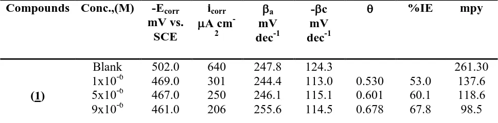
It is clearly seen from Table 1 that the values of icorr decreased and the %IE increased in the presence of pyrrole derivatives. This effect significantly increased with increasing concentrations of pyrrole derivatives and attained a maximum inhibition 82.8% at 21x10-6 M for compound (1) . We can rank compounds according to their effeciency as follow: (1) > (3) > (5)> (4)> (2).The inhibition efficiency was calculated from this equation:
%IE=(I0-Ii)/I0 X100 (1)
where, I0and Ii are the corrosion current density in the absence and in the presence of inhibitor, respectively. The values of βc and βa are not significantly affected by changing the concentration of the compounds. This demonstrates that the compounds block the anodic and cathodic active sites within the covered fraction of the electrode surface and the mechanism of the corrosion reaction not affected[18-20]. From Table 1 the values of Ecorr slightly shift to more positive potentials by increasing the concentration of inhibitors. These results indicat that these inhibitors act as a mixed-type inhibitors which act predominately on the anodic dissolution of the metal [21].
Table 1. Potentiodynamic polarization parameters for carbon steel in 1.0 M HCl solutions in the absence and presence of different concentrations of the compounds at 250C
Compounds Conc.,(M) -Ecorr
mV vs. SCE
icorr
A cm
-2
a
mV dec-1
-c mV dec-1
%IE mpy
(1)
Blank 502.0 640 247.8 124.3 261.30
[image:7.596.102.524.95.298.2] [image:7.596.56.540.655.775.2]
13x10-6 459.0 150 242.9 123.7 0.765 76.5 97.1 17x10-6 457.0 130 243.2 111.8 0.797 79.7 95.3 21x10-6 456.0 110 242.5 114.6 0.828 82.8 71.2
(2)
1x10⁻⁶ 495.0 450 244.5 124.7 0.297 29.7 244.5 5x10⁻⁶ 494.0 433 245.4 126.0 0.323 32.3 231.6 9x10⁻⁶ 493.0 401 420.1 125.0 0.373 37.3 222.3 13x10-6 492.0 370 249.4 123.4 0.422 42.2 207.9 17x10-6 490.0 340 250.8 127.2 0.468 46.8 205.8 21x10-6 488.0 330 248.8 118.8 0.484 48.4 190.2
(3)
1x10⁻⁶ 479.0 393 249.1 129.9 0.386 38.6 179.7 5x10⁻⁶ 477.0 339 247.2 120.6 0.470 47.0 154.8 9x10⁻⁶ 475.0 250 430.7 128.4 0.609 60.9 154.0 13x10-6 472.0 190 452.2 128.9 0.703 70.3 141.7 17x10-6 470.0 170 243.2 121.2 0.734 73.4 127.1 21x10-6 467.0 140 244.0 115.2 0.781 78.1 85.1
(4)
1x10⁻⁶ 491.0 445 241.0 116.0 0.304 30.4 235.80 5x10⁻⁶ 491.0 410 250.0 127.8 0.359 35.9 230.0 9x10⁻⁶ 489.0 300 240.0 123.0 0.531 53.1 219.0 13x10-6 488.0 260 245.7 115.5 0.594 59.4 204.7 17x10-6 487.0 200 242.9 120.5 0.688 68.8 198.5 21x10-6 485.0 180 246.2 110.1 0.718 71.8 177.0
(5)
1x10⁻⁶ 489.0 424 258.2 130.4 0.337 33.7 190.1 5x10⁻⁶ 487.0 355 237.5 144.5 0.445 44.5 188.7 9x10⁻⁶ 485.0 290 256.1 125.0 0.547 54.7 179.3 13x10-6 484.0 241 243.9 136.8 0.623 62.3 172.3 17x10-6 482.0 192 248.1 120.4 0.700 70.0 168.4 21x10-6 480.0 170 242.9 137.3 0.734 73.4 159.8
1E-6 1E-5 1E-4 1E-3 0.01 0.1
-1.4 -1.2 -1.0 -0.8 -0.6 -0.4 -0.2 0.0 0.2 0.4 0.6 0.8
Emv(SCE)
log
i,A/
cm
2 blank
1*10-6 5*10-6 9*10-6 13*10-6 17*10-6 21*10-6
[image:8.596.53.544.64.599.2]
Figure 2. Potentiodynamic polarization curves for carbon steel in 1.0 M HCl solutions containing different concentrations of compound (4) at 25 0C
3.2.2 Electrochemical impedance spectroscopy.
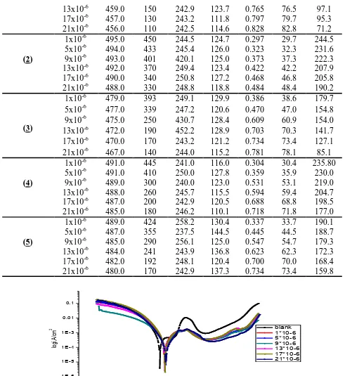
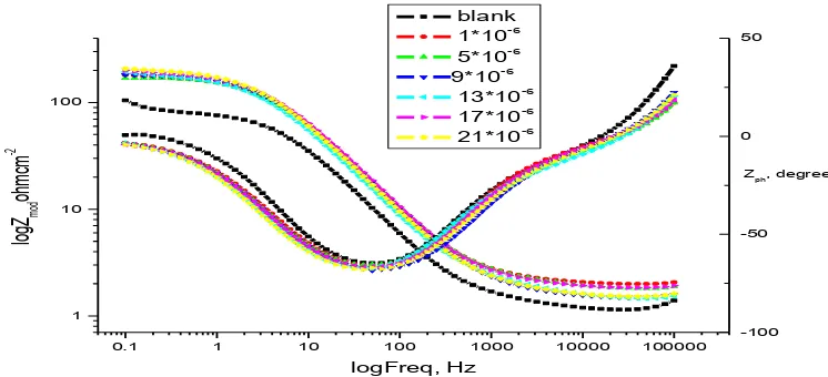
The Nyquist and Bode plots obtained for carbon steel electrode in 1.0 M HCl solution in the absence and presence of various concentrations of compounds (2) and (4) at 25 0C are shown in Figures(3-6).
Also curves (not shown) were obtained for the rest compounds. Electrochemical impedance spectroscopy was studied at corrosion potentials, Ecorr, over a frequency range of 105Hz to 0.1 Hz with a signal amplitude perturbation of 10 mV. Nyquist plots consist of capacitive depressed semicircles and this refere to as frequency dispersion. This frequency dispersion may be as a result of the roughness of the solid surface [25]. The appearance of the capacitive semicircles indicates that the corrosion of carbon steel in 1.0 M HCl solutions in the absence and presence of pyrrole derivatives is under charge-transfer control [26]. When the pyrrole derivatives added to acid solution the diameter of the semicircle increases and hence charge transfer resistance (Rct) of the corrosion reaction increases [27,28]. Increasing the concentration of the pyrrole derivatives in HCl solutions does not change substantially the shape of the semicircles confirming that these compounds do not alter the mechanism of the corrosion reaction but inhibits the corrosion processes via increasing the surface coverage of the electrode surface by an isolating adsorption layer of compounds. The simple equivalent circuit shown in Figure 7 was modeled to fit the EIS data [29]. This circuit consists of a parallel combination of a constant phase element (CPE) and the charge transfer resistance (Rct) in series connection with the solution resistance (Rs).
-20 0 20 40 60 80 100 120 140 160 180 200 220
0 50 100 150 200
blank 1*10-6 5*10-6 9*10-6 13*10-6 17*10-6 21*10-6
-Z Imag
, o
hm
cm
2
Zreal, ohm cm2
1Hz
3.15Hz
1.99Hz 1.60Hz
1.25Hz
1.28Hz 1Hz
Figure 3. Carbon steel Nyquist plots in 1.0 M HCl solutions in the absence and presence of different
concentrations of compound (2) at 25 0C.
We used the CPE element instead of the pure capacitor to reduce the effect of the roughness and the presence of adsorbed inhibitors species on the surface of the electrode [30]. CPE element represents the double layer capacitance (Cdl). The admittance and impedance of the CPE can be defined from the following equation [31,32]. (2)
where Yο is the magnitude of CPE, j2
[image:9.596.105.486.398.582.2]
electrode roughness, surface heterogeneity, and the dielectric constant [33]. The values of Cdl can be calculated using eqn. [34-36].
Cdl=Y01/nRct(1-n)/n (3)
By the following equation the inhibition efficiencies (IE) were calculated for different concentrations of pyrrole derivatives at 25 0C:
%IE=Rct-R0ct/Rct (4)
where Roct and Rct are the charge-transfer resistance values in uninhibited and inhibited solutions respectively.
0 50 100 150 200 250 300
-20 0 20 40 60 80 100 120 140 160 180 200 220 240 260 280 300 320 blank 1*10-6 5*10-6 9*10-6 13*10-6 17*10-6 21*10-6
-Z Imag
, o
hm
cm
2
Zreal, ohm cm
2 61.8Hz 1.26Hz 1.3Hz 2.5Hz 3.97Hz 1.99Hz 1.58Hz
Figure 4. Carbon steel Nyquist plots in 1.0 M HCl solutions in the absence and presence of different concentrations of compound (4) at 25 0C.
0.1 1 10 100 1000 10000 100000
1 10 100 blank 1*10-6 5*10-6 9*10-6 13*10-6 17*10-6 21*10-6 log
Z mod
oh
mcm
-2
logFreq, Hz
Zph, degree
-100 -50 0 50
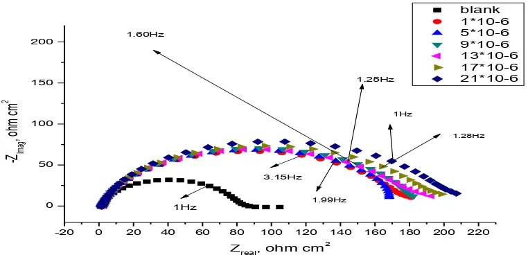
Figure 5. Carbon steel Bode plots in 1.0 M HCl solutions in the absence and presence of different concentrations of compound (2) at 25°C
[image:10.596.120.470.224.384.2] [image:10.596.120.493.441.611.2]
0.01 0.1 1 10 100 1000 10000 100000 1000000 1
10 100
blank
1*10-6
5*10-6
9*10-6
13*10-6
17*10-6
21*10-6
log
Z mod
oh
mcm
-2
logFreq, Hz
Zph, degree
-100 -50 0 50
Figure 6. Carbon steel Bode plots in 1.0 M HCl solutions in the absence and presence of different concentrations of compound (4) at 25°C
Figure 7. Equivalent circuit proposed to fit the EIS experimental data
3.2.3 Electrochemical frequency modulation (EFM).
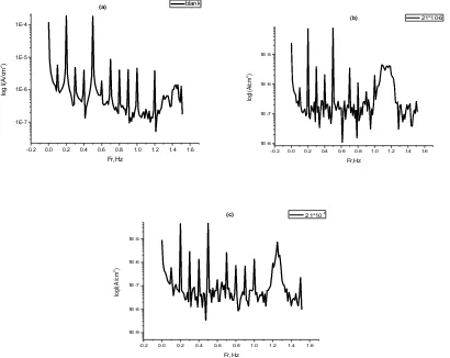
EFM technique was used for showing the behavior of carbon steel corrosion in 1.0 M HCl without and with different concentrations of inhibitors at 25 0C. The results of EFM experiments are a spectrum of current response as a function of frequency. The spectrum is called the intermodulation spectrum. Figure 8 shows intermodulation spectrum of carbon steel in 1.0 M HCl and 1.0 M HCl containing 21x10-6M from compounds (2) and (4) (as representative examples).
Similar results were recorded for the other inhibitors concentrations. The spectra contain current responses assigned for harmonical and intermodulation current peaks. The larger peaks were used to calculate the corrosion current density (Icorr), the Tafel slopes (βa and βc) and the causality factors (CF-2 and CF-3). These corrosion kinetic parameters were determined by applying potential perturbation signal with amplitude 10 mV with two sine waves of 2 and 5 Hz. The choice for the frequencies of 2 and 5 Hz was based on three arguments[38]. Table 3 demonstrates that, the corrosion current densities decrease by increasing the concentrations of the studied compounds. The inhibition efficiency (%IE) and the degree of surface coverage () increase by increasing the studied inhibitors concentrations and were calculated from the data obtained from EFM measurement using the following equation:
[image:11.596.129.499.70.227.2] [image:11.596.172.414.282.350.2]
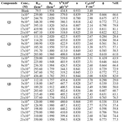
Table 2. EIS parameters for corrosion of carbon steel in 1.0 M HCl in the absence and presence of different concentrations of inhibitors at 25 0C
Compounds Conc., (M)
Rct,
cm-2
RS
cm-2
Y0X106
-1
Sn
n Cdlx104
F cm-2
%IE
Blank 79.5 1.934 434.8 0.933 3.40
(1)
1x10⁻⁶ 239.00 1.860 379.0 0.839 2.39 0.666 66.6 5x10⁻⁶ 244.70 2.020 519.0 0.780 2.90 0.675 67.5 9x10⁻⁶ 348.30 1.990 380.3 0.818 2.42 0.772 77.2 13x10-6 395.10 1.820 345.6 0.807 2.14 0.798 79.8 17x10-6 419.90 1.870 320.0 0.749 2.13 0.811 81.1 21x10-6 447.10 1.830 318.0 0.825 2.10 0.822 82.2
(2)
1x10⁻⁶ 111.10 2.020 422.5 0.855 2.67 0.284 28.4 5x10⁻⁶ 114.20 1.880 435.0 0.839 2.65 0.304 30.4 9x10⁻⁶ 180.90 1.920 422.9 0.853 2.64 0.561 56.1 13x10-6 185.30 1.950 537.0 0.833 3.38 0.571 57.1 17x10-6 191.70 1.880 413.0 0.849 2.63 0.585 58.5 21x10-6 203.80 1.960 408.0 0.849 2.62 0.610 61.0
(3)
1x10⁻⁶ 220.00 1.889 550.0 0.859 3.31 0. 639 63.9 5x10⁻⁶ 225.00 1.948 403.9 0.835 2.51 0.646 64.6 9x10⁻⁶ 236.30 1.984 426.5 0.824 2.60 0.664 66.4 13x10-6 293.60 1.759 344.3 0.841 2.23 0.729 72.9 17x10-6 347.60 1.792 319.2 0.845 2.13 0.772 77.2 21x10-6 436.40 1.782 293.1 0.844 2.00 0.820 82.0 (4)
1x10⁻⁶ 112.10 1.757 439.4 0.839 2.70 0.290 29.0 5x10⁻⁶ 118.00 1.847 447.7 0.828 2.67 0.330 33.0 9x10⁻⁶ 189.20 1.912 400.5 0.844 2.49 0.580 58.0 13x10-6 203.60 1.823 402.4 0.836 2.46 0.607 60.7 17x10-6 215.40 1.890 405.2 0.827 2.43 0.631 63.1 21x10-6 337.60 1.734 354.5 0.838 2.35 0.765 76.5 1x10⁻⁶ 120.00 1.900 480.0 0.868 2.95 0.338 33.8 5x10⁻⁶ 126.90 1.980 487.1 0.832 2.77 0.374 37.4 (5) 9x10⁻⁶ 198.00 1.810 440.2 0.830 2.67 0.598 59.8 13x10-6 270.00 1.980 410.0 0.830 2.61 0.706 70.6 17x10-6 310.00 1.990 399.4 0.831 2.60 0.744 74.4 21x10-6 350.00 1.950 390.3 0.828 2.58 0.773 77.3
[image:12.596.63.536.111.600.2]
IE) are attributed to the variations between the individual techniques and the various models that were used for the interpretation [38,41].
-0.2 0.0 0.2 0.4 0.6 0.8 1.0 1.2 1.4 1.6 1E-7
1E-6 1E-5 1E-4
lo
g
I(A/
cm
2)
Fr,Hz
blank
(a)
-0.2 0.0 0.2 0.4 0.6 0.8 1.0 1.2 1.4 1.6 1E-8
1E-7 1E-6 1E-5
lo
gI
(A/
cm
2)
Fr,Hz
21*10-6
(b)
-0.2 0.0 0.2 0.4 0.6 0.8 1.0 1.2 1.4 1.6 1E-9
1E-8 1E-7 1E-6 1E-5
lo
gI
(A/
cm
2)
Fr,Hz
21*10-6
(c)
[image:13.596.92.502.128.454.2]Figure 8. Intermodulation spectrum for the corrosion of carbon steel electrode in 1.0 M HCl solution alone (a), and intermodulation spectra for the corrosion of carbon steel in 1.0M HCl solution containing 21x10-6M of compound (2) (b) and 1.0M HCl solution containing 21x10-6M of compound (4) (c) at 250C
Table 3. Electrochemical parameters for carbon steel determined from EFM measurements in 1.0 M HCl solution without and with the addition of various concentrations of pyrrole derivatives at 25 0C
Compunds Conc.,(M) icorr
A cm
-2
a
mV dec-1
-c mV dec-1
CF-2 CF-3 %IE
blank 216.80 69.53 82.22 1.57 2.83 --- ---
(1)
[image:13.596.62.536.587.760.2]
(2)
1x10⁻⁶ 154.8 100.6 145.6 2.0 2.46 0.290 29.0 5x10⁻⁶ 144.6 86.17 123.2 1.92 3.73 0.333 33.3 9x10⁻⁶ 134.8 91.0 126.4 2.2 3.20 0.380 38.0 13x10-6 127.3 93.8 129.5 1.35 2.98 0.413 41.3 17x10-6 125.2 91.97 120.2 1.56 3.42 0.422 42.2 21x10-6 109.4 84.2 112.9 1.82 3.30 0.495 49.5
(3)
1x10⁻⁶ 130.3 19.15 21.060 2.50 3.10 0.399 39.9 5x10⁻⁶ 114.5 90.6 130.20 2.70 3.40 0.472 47.2 9x10⁻⁶ 110.9 97.76 132.60 2.40 3.50 0.488 48.8 13x10-6 70.9 89.66 125.90 2.50 2.70 0.673 67.3 17x10-6 54.09 85.77 125.00 1.77 2.97 0.750 75.0 21x*10-6 52.13 61.46 74.94 2.07 3.20 0.760 76.0
(4)
1x10⁻⁶ 147.40 99.07 140 2.097 3.62 0.32 32.0 5x10⁻⁶ 142.60 94.55 133.9 2.019 2.94 0.35 35.0 9x10⁻⁶ 82.14 63.68 78.04 2.34 3.77 0.62 62.0 13x10-6 80.14 59.00 70.27 2.19 3.33 0.63 63.0 17x10-6 73.66 62.54 76.29 2.05 3.09 0.66 66.0 21x10-6 65.58 80.66 115.7 2.03 3.55 0.697 69.7
(5)
1x10⁻⁶ 145.5 56.7 67.9 1.91 3.01 0.329 32.9 5x10⁻⁶ 140.0 63.2 99.1 1.82 3.40 0.354 35.4
9x10⁻⁶ 80.0 79.4 88.6 1.99 3.20 0.631 63.1
13x10-6 78.5 80.4 111.3 1.67 2.99 0.638 63.8 17x10-6 70.5 81.3 100.5 1.78 2.97 0.675 67.5 21x10-6 61.18 89.3 120.5 1.88 2.79 0.715 71.5
3.2.4 Adsorption isotherm
The inhibition results which obtained in aggressive acid media is assumed to be due to its adsorption at the metal /solution interface. The mode of adsorption will be dependent on factors such as the composition of compounds, chemical changes to the compounds and the nature of the surface charge on metal. An anion adsorption is favored by a positive surface charge and vice versa. In order to obtain the adsorption isotherm, the degree of surface coverage () of the compounds must be calculated. To determine the adsorption mode, there are a number of mathematical expressions having thus developed to take into consideration of non-ideal effects. The most used isotherms are Frumkin, De Boer, Parsons, Temkin, Flory-Huggins and Bockris-Swinkels [42-45]. Figure13 indicating that the inhibitors obey Langmuir adsorption isotherm given by the equation [46]:
C/=1/Kads+C (6)
where C is the molar concentration of inhibitors, Kads is the equilibrium constant of the adsorption process and is the degree of coverage by molecules of inhibitors on the metal surface.The straight line is obtained when C/ is plotted against C and the linear correlation coefficient of the fitted data is close to 1.
surface. By using the following equation we can get the values of the standard Gibbs free energy of adsorption (Gads) [47]:
Kads=1/55.5exp(-Gads/RT) (7)
Where R is the universal gas constant, T is the thermodynamic temperature and 55.5 is the concentration of water in the solution in mol / l.
0.000000 0.000005 0.000010 0.000015 0.000020 0.000025 0.000000
0.000005 0.000010 0.000015 0.000020 0.000025 0.000030 0.000035 0.000040 0.000045
comp1 comp2 comp3 comp4 comp5
C/
(mo
lL
-1 )
C(molL-1)
[image:15.596.118.479.174.313.2]Figure 9. Langmuir’s isotherm adsorption model for different compounds on the carbon steel surface in 1.0M HCl solutions .
Table 4. Langmuir adsorption parameters for adsorption of inhibitors on carbon steel in 1.0 M HCl
Compounds Langmiur isotherm
Log K M-1
R2 -Gads
Kjmol-1
(1) 5.77 0.99 47.6
(2) 5.55 0.98 04.5
(3) 5.08 0.98 04.7
(4) 5.78 0.90 04.4
(5) 5.04 0.97 04.8
The negative values of Gads reveal the spontaneity of the process of adsorption and also reveal to the stability of the adsorbed layer on the carbon steel surface. Theoretically, the values of Gads around -20 kJ mol-1 or more positive are consistent with physisorption, while those around -40 kJ mol-1 or more negative with chemisorption [48]. The values of ΔGads are in the range from -40.1 to -42.6 kJ mol-1, which automatically reflects that the adsorption mechanism of compounds on carbon steel in the 1.0M HCl solution corresponds to a chemisorption (Table 4).
3.2.5 Analysis of FT-IR spectra:
[image:15.596.44.551.393.520.2][image:16.596.40.553.255.538.2]
show that corrosion inhibition takes place through adsorption process. There is a shift in the spectra of the compounds (1),(4) when carbon steel was immersed in it to form corrosion product. This shows that there is an interaction between the inhibitor and the carbon steel substrate which resulted in inhibition. The shifts in the spectra consider as a result of the interaction between the inhibitor and carbon steel occurred through the functional groups presents in them. So, it can be affirmed that the functional group of inhibitor has coordinated with Fe2+ formed on the metal surface resulting in the formation of Fe2+ inhibitor complex on the metal surface, which promotes the inhibition of the metal sample[49].
Table 5 the data of IR spectra of compounds (1) and (4) as a solid and in 1.0M HCl without carbon steel (before) and after immersion carbon steel for 24h (after).
Compounds Groups Wavenumber
(cm−1) (solid)
Wavenumber
(cm−1) (before)
Wavenumber (cm−1)
(after)
(1)
NH2 3342-3259 3367.1 3399.89
C-H
aromatic
2969 2983.34 2983.34
C=O 1776-1650 1650.77 1652.7
S=O 1498 1420.52 1467.56
C=C
aromatic
1610 1390.24 1390.42
C-N 1317 1278.57 1255.43
(4)
C=O 1781-1700 1720-1610 1710-1600
C=C aromatic
1598 1562 1500
C-N aliphatic
1155 1087 1010
3.2.6 UV-visible analysis
200 300 400 500 600 700 800 900
-0.4 -0.2 0.0 0.2 0.4 0.6 0.8 1.0 1.2 1.4
Ab
s.
wave length(nm)
[image:17.596.101.476.85.247.2]Before
Figure 10. UV-Visible spectra of the solution from 1.0 M HCl solution containing 21x10-6 M from compound (4) before carbon steel immersion
200 300 400 500 600 700 800 900
-0.4 -0.2 0.0 0.2 0.4 0.6 0.8 1.0 1.2 1.4
Ab
s.
wavelength
After
Figure 11. UV-Visible spectra of the solution from 1.0 M HCl containing 21x10-6 M from compound (4) after 24h of carbon steel immersion
3.3. Mechanism of inhibition
The adsorption of pyrrole derivatives compounds can be attributed to the presence of polar units having atoms of nitrogen, sulphur , oxygen and aromatic/heterocyclic rings. Therefore, the possible reaction centers are unshared electron pair of hetero-atoms and electrons of aromatic ring .
The adsorption and inhibition effect of pyrrole derivatives compounds in 1.0 M HCl solution can be explained as follows:
[image:17.596.127.457.319.484.2]
The order of inhibition is decreased as the following order: 1 > 3>5>4>2. This due to the difference in number of nitrogen atoms,oxygen atoms and sulpher atoms in the compounds , which increase the electron charge density on the molecule.
4. CONCLUSIONS
The results obtained show that pyrrole derivatives are good corrosion inhibitors for carbon steel under acidic conditions. The maximum inhibition efficiency was 82.8% for compound (1). Excellent agreement between the inhibition efficiencies calculated using different techniques was obtained. The adsorption of the Pyrrole derivatives onto the steel surface was characterized by the decrease in: (i) the cathodic and anodic current densities observed in the potentiodynamic polarization curves carried out in the presence of pyrrole derivatives, (ii) the double-layer capacitance computed from electrochemical impedance spectroscopy experiments and (iii) electrochemical frequency modulation (EFM). The adsorption behavior of the Pyrrole derivatives are consistent with Langmuir adsorption isotherm. inhibitors are adsorbed on Carbon steel surface following chemisorption mechanism. The results of polarization indicated that compounds are of mixed type. A good agreement was obtained between all the investigated electrochemical techniques. The results obtained from FTIR, UV-visible analysis and Langmuir adsorption isotherm suggested that the mechanism of corrosion inhibition is occurring mainly through adsorption process.
References
1. M. Yadav, D. Behera, S. Kumar and R. R. Sinha, Ind. Eng.Chem. Res., 52(2013) 6318.
2. Y. M. Tang, X. Y. Yang, W. Z. Yang, R. Wan, Y. Z. Chen and X. S. Yin, Corros. Sci., 52(2010) 1801.
3. M. B. Cisse, B. Zerga, F.El Kalai, M.Ebn Touhami, M.Sfaira, M.Taleb, B. Hammouti, N.Benchat, S.El Kadiri and A.T. Benjelloun, Review and Letters, 18(2011)303.
4. A.Y. Musa, R.T.T.Jalgham and A.B. Mohamad, Corrosion Science, 56(2012) 176. 5. S.E.Nataraja, T.V.Venkatesha and H.C.Tandon, Corrosion Science, 60( 2012) 214. 6. E.A. Noor, A.H. Al-Moubaraki, Mater. Chem. Phys.,110(2008) 145.
7. Y. El Kacimi, R.Touir, M. Galai, R. A. Belakhmima, A. Zarrouk, K.Alaoui, M. Harcharras, H. El Kafssaoui and M. Ebn Touhami, J. Mater. Environ. Sci., 7(2016) 371.
8. S.T. Keera and M. A. Deyab, Colloids Surf. A: Physicochem. Eng. Aspects, 266(2000)129. 9. A. Chetouani, B. Hammouti, T. Benhadda and M. Daoudi, Appl. Surf. Sci., 249(2005), 375. 10.B.P. Etherton, R.Krishnamurti and S. Nagy, US patent , (5)554(1996)775.
11.A. Kaledkowski and A.W. Trochimczuk, React. Funct.polym., 66 (2006) 740. 12.Y. Zhu,A.Rabindianath, T.Beyerlein and B.Tieke, macromolecules,40(2007) 6981.
13.H. Lee, J.Lee, S.Lee, Y.Shin,W.Jung, J.H.Kim, K.Park, K.Kim, H. S. Cho and S. Ro. Bioorg., Med.Chem.Lett, 11(2001) 3069.
14.D. O. Hagan, Nat. Prod. Rep,17(2000)435.
15.V. J. Gelling, M. M. Wiest, D. E. Tallman, G.P. Bierwagen and G. G.Wallace, Prog.Org.Coat, 43(2001)149.
16.K. M. Govindaraju, V. Collins Arun Prakash and V. ManivannanL. Kavitha, J Appl Electrochem., 39(2009)269.
18.J. Aljourani, K. Raeissi, M. A. Golozar, Corros. Sci., 51(2009)1836.
19.H. M. Abd El-Lattef, V. M. Abbasov, L. I.Aliyeva, E. E. Qaismov and I.T. Ismayilov, Mater.Chem. Phys., 142(2013)502.
20.R. Mehdaoui1, A. Khelifa1, A. Khadraoui1 , O. Aaboubi, A. Hadj Ziane1, F. Bentiss and A. Zarrouk, Res Chem Intermed, 42(2016)5509.
21.I. Ahamad and M. Quraishi, Corros. Sci., 51(2009) 2006.
22.S. Zhang, Z. Tao, W. Li and B. Hou, Appl. Surf. Sci., 255(2009) 6757.
23.M. Outirite, M. Lagrenee, M. Lebrini, M.Traisnel, C. Jama, H. Vezin and F. Bentiss, Electrochim. Acta, 55(2010)1670.
24.G. E. Badr, Corros. Sci., 51(2009) 2529.
25.M. Palomar-Pardav´e, M. Romero-Romo, H. Herrera- Hernndez, M. A. Abreu Quijano V. Natalya- Likhanova, J. Uruchurtu and J. M. Jurez-Garca, Corros. Sci., 54(2012) 231.
26.K. F. Khaled and N. Hackerman, Mater. Chem. Phys., 82(2003) 949.
27.F. B entiss, M. Outirite, M. Traisnel, H. Vezin, M. Lagrenee, B. Hammouti, S. S. Al-Deyab and C. Jama, Int. J. Electrochem. Sci., 7(2012) 1699.
28.I. Ahamad, R. Prasad and M. A. Quraishi, Corros. Sci., 52(2010) 1472.
29.E. E. Oguzie, V. O. Njoku, C. K. Enenebeaku, C. O. Akalezi and C. Obi, Corros. Sci., 50(2008) 3480.
30.M. Bouklah, B. Hammouti, M. Lagrenee and F. Bentiss, Corros. Sci., 48(2006) 2831. 31.H. Ashassi-Sorkhabi and E. Asghari, Electrochim. Acta, 54(2008) 162.
32.B. D. Mert, A. O. Y¨uce, G. Kardas¸ and B. Yazıcı, Corros. Sci., 85(2014) 287. 33.Z. Lukacs, J. Electroanal. Chem., 68(1999) 464.
34.B. Hirschorn, M. E. Orazem, B. Tribollet, V. Vivier, I. Frateur and M.Musiani, J. Electrochem. Soc.,157( 2010) C458.
35.B. Hirschorn, M. E. Orazem, B. Tribollet, V. Vivier, I. Frateur and M. Musiani, Electrochim. Acta, 55(2010) 6218.
36.C. H. Hsu and F. Mansfeld, Corrosion,57( 2001) 747.
37.K. R. Ansari, M.A.Quraishi and A. Singh, Corros. Sci., 79(2014) 5.
38.R. W. Bosch, W. F. Bogaerts and B.Syrett, Proc. 8th International Symposium on Electrochemical Methods in Corrosion Research modulation (EFM) technique, Nieuwpoort, Belgium,
May2003,4– 9
39.A. S. Fouda, A. A. Nazeer and A. Saber, J. Korean Chem. Soc., 58(2)(2014) 160. 40.K. F. Khaled1 and N. S. Abdel-Shafi1, Int. J. Electrochem. Sci.,8( 2013) 1409. 41.M. N. EL-Haddad and A. S. Fouda, ChemEngComm, 200( 2013) 1366.
42.Z.M. Hadi and J. Al-Sawaad, Mater. Environ. Sci,. 2(2)(2011) 128. 43.P. N. G.Shankar and K. I.Vasu, J. Electrochem.Soc. India.,32(1983) 47. 44.A. Amin, K.F.Khaled, Q.Mohsen and A.Arida, Corros. Sci.,52(2010)1684.
45.S. A. Umoren, O.Ogbobe, I.O.Igwe and E. E. Ebenso, Corros. Sci., 50(2008)1998.
46.R. Solmaza, G. Kardas, M. Culha, B.Yazıcı and M. Erbil, Electrochim. Acta, 53(2008) 5941. 47.Mahmoud N. El-Haddad, RSC Adv., 6(2016) 57844.
48.A. K. Singh and M. A. Quraishi, Corros. Sci.,53( 2011) 1288.
49.S. S. Syed Abuthahir, A. Jamal Abdul Nasser and S. Rajendran, Eur. Chem. Bull., 2(11)(2013) 932.
50.J. Jeyasundari, S. Rajendran, R. Sayee Kannan and Y. Brightson Arul Jacob, Eur. Chem. Bull., 2(9)(2013) 585.
51.N.O. Obi-Egbedia and I.B. Obotb, Arabian Journal of Chemistry, 6(2013) 211.