Rochester Institute of Technology
RIT Scholar Works
Theses
Thesis/Dissertation Collections
8-2007
Methodology and optimizing of multiple frame
format buffering within FPGA H.264/AVC
decoder with FRExt.
Timothy Aaron Stotts
Follow this and additional works at:
http://scholarworks.rit.edu/theses
This Thesis is brought to you for free and open access by the Thesis/Dissertation Collections at RIT Scholar Works. It has been accepted for inclusion in Theses by an authorized administrator of RIT Scholar Works. For more information, please [email protected].
Recommended Citation
Methodology and optimizing of multiple frame format
buffering within FPGA H.264/AVC decoder with FRExt.
by
Timothy Aaron Stotts
A Thesis Submitted in Partial Fulfillment of the Requirements for the Degree of
Master of Science in Computer Engineering
Approved By:
Supervised by
Assistant Professor Dr. Marcin Lukowiak
Department of Computer Engineering
Kate Gleason College of Engineering
Rochester Institute of Technology
Rochester. New York
August 2007
Marcin tukowiak
Dr. Marcin Lukowiak
Assistant Professor, RIT, Department of Computer Engineering
Primary Adviser
Ken W. Hsu
Dr.
Ken W. Hsu
Professor, RIT, Department of Computer Engineering
Secondary Adviser
Mark Grabosky
Mark Grabosky
Thesis Release Permission Form
Rochester Institute of Technology
Kate Gleason College of Engineering
Title: Methodology and optimizing of multiple frame format buffering
within FPGA H.264/AVC decoder with FRExt.
I, Timothy Aaron Stotts, hereby
grant permission to the Wallace Memorial Library to
reproduce my thesis in whole
or in part
.
Timothy Aaron Stotts
Timothy Aaron Stotts
Dedication
To Christ
Jesus,
myone truesource of peace."Peace I leavewithyou,my peaceIgive unto you: not as theworldgiveth,
Acknowledgments
A special thank you to each of my advisers for sharing their time and experience; and
especially toDr. Lukowiakfor hispatientguidance, andMark
Grabosky
atXelic,
Inc. for encouragingandequipingmetopullthrough. Thankyou alsotoThomas Warsaw for manyAbstract
Digitalrepresentationofvideodata isan
inherently
resourcedemanding
problemthatcon tinues tonecessitate the developmentandrefinement ofcodingmethods. The H.264/AVCstandard, along with its recent
Fidelity
Range Extensions amendment(FRExt),
is quicklybeing
adopted asthe standard codec for broadcastanddistributionofhighdefinition video.The FRExt amendment, while not necessarily affecting the overall decoder architecture,
presents an added complexity of providing efficient memory management for
buffering
intermediate frames of various pixel color samplings anddepths.Thisthesisevaluatedtherole of
designing
theframe bufferofahardwarevideodecoder,
with integrated supportfor the H.264/AVC codec plusFRExt. With focus on organizing
external memory data access, the frame bufferwas designedto provide intermediate data storageforthe
decoder,
whileusingan efficient store andloadschemethat takesintoconsiderationeachframepixel formatofthevideodata.
VHDLwasused tomodel theframebuffer. Exploitation ofreconfigurability and
post-synthesis FPGA simulations were used to evaluate
behavior,
scalability and power con sumption, whileprovidingananalysis of approachestoadding FRExtto thememory man agement. Real-time buffer performance was achieved fortwo common frame formats at1080 HDresolution; and aninnovativepipelinedesignprovides dynamic switchingoffor
mats between video sequences. As an additional consequence ofverifying the model, a
preexisting Baseline H.264/AVC decoder testbench was augmented to support
testing
ofContents
Dedication ... iii
Acknowledgments ... iv
Abstract v
Glossary
xiv1 Introduction ... 1
1.1 Background 1
1.2 Thesisobjective 4
1.3 Thesischapter overview 6
2 Video
Coding
... 72.1 Y'CbCrcolormodel 7
2.1.1 Y'CbCr sub-sampling 9
2.2 H.264/AVCoverview 12
2.2.1 H.264/AVC coding summary 14
2.2.2 H.264/AVC
Fidelity
Range Extensions summary 172.3 Thesisrelevance and specifics 19
2.3.1 H.264/AVC data
buffering
flow 192.3.2 H.264/AVC data
buffering
organization 202.3.3 Macroblockpixel types 23
3 H.264/AVC Research .25
3.1 Decoder memorycase studiesand research 25
3.1.1 Identification ofmemorycomponents 26
3.1.2 Optimizationtechniques 27
3.2 Analysisof published results 30
4 Requirementsand
Modeling
324.1 Augmentation ofdecodersystem 32
4.2 Algorithms used
by
theframe buffer. 324.2.1 Intraprediction
buffering
requirements 344.2.2
Deblocking
filterbuffering
requirements 364.2.4
Combining
ofbuffering
mechanisms 374.2.5 Referencepicturemanagement 37
5 SynthesizableImplementation 40
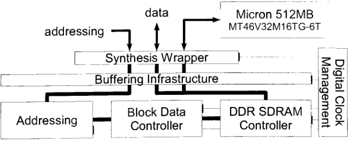
5.1 External memory storage and control 40
5.1.1 DDR memorycontrol 42
5.1.2 Block datacontroller 44
5.1.3 Implementation
hiearchy
455.1.4 External DDR interface 46
5.2 Frameorganization andaddressing 46
5.2.1 Macroblock identification andframe slotting 49
5.2.2 MacroblockaddressmappingwithFRExt 51
5.2.3 Framestoragemarking 53
5.2.4
Sliding
windowimplementation 545.3 Synthesisparameters 55
5.4 Frame buffer interfaceandpipelining 57
5.4.1 Framebuffer RTL interface 57
5.4.2 Pipeline semantics 62
5.5 Dual RAM frame buffer 63
5.5.1 Dual DDR SDRAM design 65
6 Verification- HDL Model
Functionality
. . .... 696.1 Unit
testing
696.2 In-systemverification 71
6.2.1 Augmentationofthedecodersystem 71
6.2.2 Testbenchredesign 74
6.2.3 Videosequences 76
6.2.4 Functional simulation 77
6.2.5 Post-synthesissimulation 79
7 Results andAnalysis ... 81
7.1 Implementation analysis gl
7.2 Synthesisresource analysis 86
7.3 DDR
timing
analysis 377.4 H.264/AVC
timing
analysis 907.5 Powerconsumptionanalysis 92
7.6 Costanalysis 94
8 Conclusions 97
8.1 Synthesizablemodels 97
8.2 Proposed system
interfacing
99
SoftwareToolsandDeliverables 106
A.l Software tools 106
A. 1.1 Video processingand
display
106A. 1.2 FPGAdesignand simulation 107
List
of
Figures
1.1 Digitalrepresentationof a picture intermsofdatasize 1 1.2 Digitalrepresentationofuncompressedvideo intermsofdatasize 2 1.3 Theextradimension of pixel size upontotalpicturedatasize 3
1.4 Internal partitioningofframe buffer design 4
1.5 Video decoder systempartitioningaugmentedfortestingframe buffer. ... 5
2. 1 RGB vs. Y'CbCr decompositionofa
"foreman"
testframe 8
2.2 Y'CbCr sub-sampling 4:4:4 10
2.3 Y'CbCr sub-sampling 4:2:2 11
2.4 Y'CbCr sub-sampling 4:2:0 11
2.5 Y'CbCr sub-sampling 4:0:0 12
2.6 ScopeofH.264/AVC Standard: only
decoding
[24]
14 2.7 Thecorrelationbetweensource(uncoded)
pictureframesand encoded slices. 152.8 Pixel samplingand
depth,
increasingly
stackedby
FRExtprofile.[24]
... 18 2.9Buffering
withinthe H.264/AVCHypothetical Reference Decoder.[9]
. . . 202.10 DPB operation: macroblock
in,
macroblock out 212.11 Buffera row of macroblockstoretain neighborMBs 21
2.12 Organizationofthereference frame buffer 22
3.1 FPGAhybridon-chip, off-chip decoderarchitecture proposedin [21]. ... 26
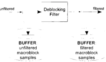
4. 1 Videodecodersystem architecture anddataflow 33 4.2 IntraPrediction macroblock neighborpermutations 34 4.3 Maindatapath
"tap"
locationsfor
buffering
365.1 Vendor-suppliedXilinx Spartan 3E DDR SDRAMcontroller. 43
5.2 CustomizedXilinx Spartan 3EDDRSDRAMcontroller 43
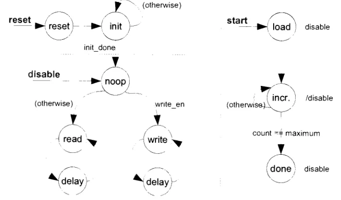
5.3 Blockdatacontrollerstate machines 44
5.4 Internal partitioningofframe buffer design 45
5.5 ExternalDDR interface 47
5.6
Binary
16x8 sub-macroblockmemorymapsforeach 8-bitsub-sampling. . . 49 5.7 SingleRAM frame buffer innerand outerinterfaces 58 5.8 DualRAM frame buffer innerand outerinterfaces 656.1 Testbench flowwith emphasis ondataprocessing 74 6.2 Testbench flowwith emphasis on storageoperations 75
List
of
Tables
2.1 Compressionratios forvariousY'CbCrsub-samplings 12
2.2 H.264/AVC standard
drafting by
year.[19]
132.3 Someofthealternatenames givento the H. 264/AVC standard.
[19]
.... 13 2.4 Thethreebasic slicetypes specifiedby
H. 264/AVC 16 2.5Sub-sampling
factor forallsub-samplingratios 232.6
Binary
sizes of amacroblockand frame 244.1 Macroblock stagesof operation whilepassingthroughthedecodersystem. . 33
4.2 Example
buffering
size requirementsfor intraprediction 35 4.3 Example ofreferencepicturelistupdates.[16]
395.1 External DDRpins 47
5.2 Uniqueaddressesrequiredtostore 16x8 sub-macroblockforallpixel types. 49 5.3 Example
(exact)
ranges of macroblocknumbers 505.4 Example
(arbitrary)
rangesofslotIDs 515.5
Addressing
combinationsloadedby
blockcontroller 535.6 Interpretation offrame marking booleans 53
5.7 Examplecontentsofframe buffermetadata 54
5.8 Structural frame buffersynthesis parameters 56
5.9 Digitalpatternsfor markingslots 62
6.1 Performancemodificationsto the originaldecodermodel 72 6.2 Performanceenhancementsto theoriginaldecodermodel 72 6.3 Functional correctionsto theoriginaldecodermodel 73
6.4
Key
H.264/AVC testsequences 766.5 Typical simulationCPUtime andmemory forsome sequences 78
7.1 Single RAM frame buffer synthesis, fullpin-out 86
7.2 Dual RAM frame buffersynthesis, fullpin-out 87
7.3 Comparison offramebuffersynthesis 87
7.4 Singlexl6DDR SDRAMbandwidth 88
7.5 StripedDual xl6DDR SDRAMbandwidth 89
7.6 xl6DDRSDRAM bandwidth variance 89
7.7 Single xl6DDR SDRAMframespersecond
91
7.8 Stripedxl6DDR SDRAM framespersecond 0|
7.9 FPGA devicepower consumptionofframe bufferpost-synthesis
7.10 Estimatedunitdevicecostinpurchasequantityof 100 95
Listings
5.1 RTLpseudo code forstoreoperation 60
5.2 RTLpseudo codeforworst-caseloadoperation 60
5.3 RTLpseudo codefor best-case load operation 61
5.4 Exampleincorrectuse ofdata striping 67
5.5 RTLpseudo codeforstriped store operation 67
Glossary
C++
C++ or C Plus Plus. A widely used object-oriented software programminglanguage.
CAVLC Context Adaptive VariableLengthCoding. An
improved,
context-adaptive version ofVLC usedin theH.264/AVC Baseline Profile.
D
DVD Digital Video Disk or Digital Versatile Disk. A popular optical disk storage
technology
usedforvideosand other applications thatrequirelargeamounts ofstorage.
F
FRExt
Fidelity
Range Extensions An amendment to H.264/AVC approved in 2004providing
"professional"
codingtoolsandfour new
"High"
profiles.
H
H.264/AVC ITU-T H.264 and ISO/IEC 14496-10. Video coding standard approved in 2003
jointly by
ITU-TandISO/IEC. Delivers significantly bettercompressionHDTV
High DefinitionTelevision. Anumber ofhigh-quality
resolutions standardizedfor television use. Includes 1080x720 and 1920x1080 resolutions, and two different forms of pixelarrangement(progressive andinterlaced).
I
IDR Instantaneous Data Refresh. A codedframe composed ofonly I or SI slices.
The
decoding
of an IDR frame signals the reference picture list to mark itsentirelistofframesas nolongerneededforreference.
ISO/IEC
International Standards Organization/International Electrotechnical Commission. ISO isaninternational
body
responsible fordeveloping
and maintaining a range of standards across many disciplines. IEC isthe commission specifi callyresponsible for electricaltechnologies,including
MPEG video compres sion standards.ITU-R International Telecommunications Union
(ITU)
Radiocommunication Sector.Responsiblefor regulatingtheradio
frequency
spectrumusedforwireless communications
by industry
andgovernment worldwide.ITU-T InternationalTelecommunications Union
(ITU)
TelecommunicationsStandardization Sector. Responsible for
developing
andmaintaining jointindustry
andgovernment standards forworldwidetelecommunications technology.
M
Q
QCIF
Quarter-resolution Common Image Format. Defines an image size of 176pixels wide
by
144pixelshigh.R
RAM
RIT
Random Access Memory. Type ofreusabledata storageforwhichits contents
canbeaccessedin anyorder, and withoutanyphysicalmoving parts.
Rochester InstituteofTechnology. The author'sprimary university atthe time
ofpublishing.
VCEG Video
Coding
Experts Group. A group fromthe ITU-Tresponsible foradopting
anddefining
video compression standards.VCL Video
Coding
Layer. The layerintheH.264/AVC standardthatcontains actualvideoinformation.
Verilog
Verilog. Apopular computerlanguageusedfor modelinganddescribing
hard ware.VHDL
Very
High Speed Integrated Circuit(VHSIC)
Hardware Description Language(HDL). A popular computerlanguageused for modelingand
describing
hard ware.Y'CbCr Y'CbCrorYCC orYPbPr. A digital equivalent oftheYUV color model,con
taining
oneluma,
one bluechrominance and one red chrominancevalue. AlY'CbCr is specified
by
adifferent set offormulas.Analog
component signalswhich carrytheY'CbCr data are sometimestermedYPbPr.
YUV
YUV. A three component colormodel defined in terms of one luma andtwochrominance values. YUV is commonly used within analog video broadcast
formats to
lossy
compress RGB pixelsby
discarding
a significant portion ofthe color
data,
whileretaining much ofthe human perceptible image quality.Chapter
1
Introduction
1.1
Background.
The atomic unit of digital graphics
technology
is the pixel, or "picture element"'.
Adigital image when renderedfor
display
whether a still picture, a printed graphic, or anindividual frameof a video sequence consists of a
finite,
two-dimensionalarrayof points.Eachpoint,orpixel,isrepresented
by
a sequence ofbinary
datathatdescribestheintensity
and color of that individual point. A single image
typically
consists of a uniform pixeltype viz., each point is described
by
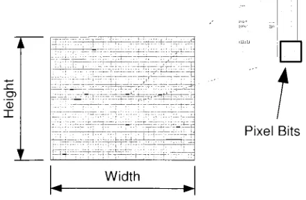
exactly the same manneras all of the other pointswithinthatimage. The digitalrepresentationof a singleimage is depictedwithFigure 1.1.
'CD
I
-^i - "
. ,: . ~ "
: -
[image:19.491.132.352.446.590.2]-A-. *tF
"T^-| :X^tjd^ld^ "
H H--JAH]
-^r
:-
i-!-] UAl ::-lffi -^-f^rf IH:' f If- -
-, tljtil 1 [1
""-i Ar &: d " ::=-4=H-H-^A[fl1| :^1
.... l<< ''1 " i:
Width
t
Pixel Bits
Figure 1.1: Digitalrepresentationof a pictureintermsofdatasize.
As shown, thequantitative metricsthatdeterminethetotal
binary
datasizeof aniffif<X
are: the number ofbits necessary to represent a singlepixel, andthe total number ofpix
els.
Considering
only pictures, or rectangularimages,
the totalbinary
size of apicture is computed as follows:PictureBits =
(WidthlnPixels
*HeightlnPixels)
*{Bits
PerPixel)
(1-1)
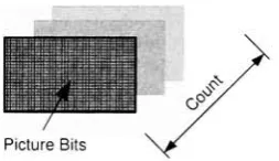
When considering digital video technology, the appearance of continuous motion is facilitated
by
rapiddisplay
of a sequence of pictures, with most picturesbeing
a slightchangein appearancefromtheprevious. Thedatasizeof anuncompressed videosequence
then increases multiplicatively fromthe aboveequation, as shownin Figure 1.2.
VideoBits =
(PictureCount)
*(PictureBits)
(1.2)
[image:20.491.187.314.367.440.2]Picture Bits
Figure 1.2: Digitalrepresentation ofuncompressed videointermsofdatasize.
Video coding standards suchas H.264/AVC provide a setoftools
by
which thebinary
dataofa source video sequencemay bemodified and compressed into amuch smallerbinaryrepresentation,whileretainingameasure ofthehuman-perceptiblevisual quality. The
compression operatesprimarilyontheassumptionthatneighboringpicturescontainalarge quantity ofsimilar
(redundant)
pixels. Thecompressed, andthus smaller, representationis then stored or transmitted in various manners. However, whendecoding
this compressedsome pictures are stored within a frame buffer 2 for later reference
by
thedecoding
al gorithms. This intermediate storage of select pictures produces a potential performance concern for hardwareimplementationsdueto thememorystoreandloadof significantdata quantity.Very
specific to H.264/AVC is the recent FRExt amendment applied to this standard.While many video coding standards allow for only a single pixel type of a specific bit
size, theFRExtamendmentintroducestheoptiontoencodeavideo sequence withoneofa varietyof pixeltypes. Eachpixeltypeusesadifferentnumberof samplebitsandadifferent Y'CbCr sub-sampling to represent
itself,
thus significantlyimpacting
thebinary
sizes ofboth the compressed and uncompressed
data,
irrespective of the total number of pixels.The impact of changing pixel representation upon the total picture data size is depicted
with Figure 1.3. This additional
"dimension"
by
which the picture data representationmay differ between video sequences introduces an additional complexityto both the data quantity and accessbehaviorofthedecoder memorymanagement.
., Width
(pixels)
CD X
sz D)
CD
1
Width
(bits)
sz O)
CD
1000 0110
[image:21.491.118.412.369.516.2]4?)
Figure 1.3: Theextradimensionofpixelsize upon totalpicture datasize.
2Framebuffer is a more generic termfor thistypeofhardware component. TheH.264/AVC standard
1.2
Thesis
objective.
This thesis provides an initial methodology for
implementing
and optimizing the framebufferof ahardware H.264/AVCdecoderwithFRExt. A frame bufferwith external mem
orywasimplementedwiththe
functionality
oftheH.264/AVCcodec plus supportforeach oftheY'CbCrpixelformatsofthe FRExt"High"profiles. The frame bufferwas designed tobeasinglecomponent,scalabletovariousmemorycapacities andframeresolutions, and
capable ofefficiently switching frame formatmode (pixeltype)in-hardware.
Additionally,
the organizational and access schemes ofthe frame bufferweretailoredto handle each of
the decoded framepixel
formats,
with considerations towardoptimization. Figure 1.4 depictstheinternal partitioningoftheframe buffercomponentaccordingto
functionality
and logical interface. /*-Bl RAM Command External Memory Controller Intra Prediction1
ockController Address Counter DeblockingFilter \^ -a
/
'y
-^ /Ar Inter Prediction + ^ o / O/ FRExtScaling H.264/AVC Mapper SlidingWindow Control Frame Buffer External Memory
Figure 1.4: Internal partitioningofframe buffer design.
Theframe bufferwasmodeledusingtheVHDLhardware description languageinthree differentforms: azero-timesimulation-onlybehavioralmodel, andtwodifferentsynthesiz
able descriptions for
implementing
inhardware. Both hardware models specificallytarget Xilinx FPGAtechnology
withexternal DDR SDRAM memory; one using a single memory chip, and the other striping data between two memory chips. All three models were
verified against each otherfor identical
functionality
within afull simulation-onlydecodernetlistforms.
Finally,
each hardwaremodelwas verifiedas parameterizablepre-synthesisto support any combination of the three H.264/AVC frame
buffering
needs: intraprediction, interprediction, and
deblocking
filter;
to optionally support multiple frameformats;
andto optionallysupportthe slidingwindow algorithm.
As an additional contribution, a simulation-only VHDL model of aH.264/AVC Base
line decoderwas augmentedtosupportsimulation ofHDresolutions, and emulatememory
supportformultiple pixelformatsoftheFRExt"High"
profiles. Theseadditionsincludeda
new queuingtestbenchdesignthatwould exercisetheframe buffer accordingto thebehav
iorof a real video sequence. The preexisting, incomplete Baseline softwarebuffermodel
was one such component augmented within the
decoder,
and its operation within the fulldecodersystem is depicted in Figure 1.5.
Inter Prediction
1
c
1
Frame
Buffer
VideoHeader | |
Intra Prediction L
_J
I,
Control
Stream Parser
Inverse ^ Quantizer
Inverse Transform
iDeblocking Filter
: ?"*
ompressed uncompressed
video video
Figure 1.5: Video decodersystempartitioningaugmentedfor
testing
frame buffer.The decoderoperation with respectto these additionalcoding toolswasverified using
referenceH.264/AVC codec software
[18]
written in C++. After several video sequenceswere usedtodemonstratesufficientlycorrectbehavioroftheVHDL decoder incomparison
with thereference software, thedecoderwasthen usedasabasis forin-system simulation
and validation ofthe synthesizableframe buffer
description,
bothpre-and1.3
Thesis
chapter overview.This thesis begins with a discussion of video coding concepts and the H.264/AVC stan
dard in Chapter 2. An overview ofbasic video compression and color modelsis presented
along with a synopsis ofthe H.264/AVC standard. Chapter 3 thenprovides an overview
ofpublishedresearch on the topicofmemory management within ahardware H.264/AVC
decoder. Potential methods ofoptimizing FRExt within a hardware decoder are conjec
tured. Chapter 4 discusses the conceptual modeling ofthe frame buffer implemented
by
thisthesis,
including
requirements, algorithms, anddata flow.The actual frame buffer implementations performed are presented in Chapter
5,
withadetailed look at synthesizable
descriptions,
andconsiderations towardfunctionality
andoptimization. Chapter 6 discusses the verification of each model ofthe the frame buffer
component, and how
they
were verified against each other with representative video sequences. The resultsoftheverifieddescriptions are presentedin Chapter
7,
with simulatedperformance analysis for the hardware frame
buffer, taking
into consideration trade-offsbetween speed, powerconsumption, and complexity.
Finally,
Chapter 8 concludesthe thesiswithasummation ofresultsand potentialimprovements. Italso proposesan
interfacing
scheme to integrate the frame bufferinto afull pipelined H.264/AVCplus FRExt decoder
Chapter 2
Video
Coding
Thischapter
briefly
discussesthe theY'CbCrpixel color model usedby
manyvideocodecs,andalsoprovides backgroundonthe
history,
concepts, and application ofH.264/AVC.2.1
Y'CbCr
color model.Y'CbCristhepredominatecolor model used withindigitalvideocodingstandards, includ
ing
H.264/AVC. Some popular color models, such as RGB and YMCK(commonly
usedwithindisplays and printersrespectively), produce a range ofcolors
by
mixture ofthree orfour linearchannels. These color channels are similar in effect to the mixing of primary
paints on an artist's palette. Unlike linearcolormodels, Y'CbCrrepresents pixel
intensity
asits owncomponent, butwith some residual interdependencewiththecolorcomponents.
"Y"
representsthelumacomponent, and "Cb"
and "Cr"
representtheblueandred chroma
components respectively. The
"luma"
component is gamma-corrected
luminosity,
andthe"chroma"
components are gamma-corrected chrominance. A comparison of linear RGB
decompositionand gammaY'CbCrdecomposition isshownwithFigure 2.1.
Thegoal oftheY'CbCrmodelistorepresentR'G'B' (gamma-corrected
RGB)
data in acompressedform
by
discarding
some ofthelessessential sub-pixel color resolution. Sincethehumaneyeispredominately sensitiveto
brightness,
and alsothecolorgreen,compress
-(a) Original.
il-X
(b) R.G,Bchannelsrespectively.
X
(c) Yd Cb. Crcomponents respectively.
Figure2.1: RGB vs. Y'CbCr decompositionofa
"foreman"
test frame.
bit size while retaining much of the original appearance. Multiple sub-sampling formu
las exist for
Y'CbCr,
and several are standardizedby
the ITU. One conventional Y'CbCrformusedto transform source videodata justpriortoencodingwithH.264/AVC andother
codecs is:
Y'
= KR*R +
{l-KR
1
(
B-Y Cb9 1
-Kb
C
KB)
*G +Kb
*B\
1/
R-Y9 1- A' R
(2.1)
The gamma values
KR
andKB
are left unspecified until a specificdisplay
technology
isdetermined;
butKR
+KB
< 0.5 may be assumed. Acommon choiceforcurrent displaysis:
KR
0.2120,
KB
= 0.0722 [19]. As shown, the luma component does depend onthe original red andblue channels, but is primarily influenced
by
the green. The choice ofgamma valuesis dependentupontheintendedvideo
display
technology;forexample. CRTand LCD displays have somewhat different ideal gamma values, as do conventional and
highdefinitiontelevisions.
With respect to digital video coding, sample values are
typically
stored and operatedupon asintegers. ITU-R BT.601 specifies aformof8-bitintegermatrix multiplication that
canbe usedtoperformtransformations betweenR'G'B' and Y'CbCr [6, 8j. Equation
(2.2)
demonstrates transformation of8-bit perchannel
R'G'B'
equation
(2.3)
demonstratestransformationof8-bitper sampleY'CbCrto8-bitperchannelR'G'B'. When the matrix coefficients are chosen properly for the target technology, the transformationsalonewillincur very little data
loss;
onlysomuchasresultsfromprecisionerrorsinternal to themathematical expressions.
y Cb Cr 1 256 77 150 -44 -87 131 -110 29 -131 -21 R' 16 G' + 128 B' 128
(2.2)
R! G' B' 1 256256 0 351
256 -86 -179
256 444 0
r --16 Cb- -128 Cr- -128 (2.3)
2.1.1
Y'CbCr
sub-sampling.By
itself, transforming
a picture from RGB to Y'CbCr does not reduce the size of thebinary
representation. Due to the near separation ofluminosity
and color, sub-sampling canbeusedduring
orfollowing
transform toreducethebinary
sizeofthechroma samples. This form of reduction requires that the picture be partitioned into"macroblocks." Each
macroblock is a base square unit ofpixels, possibly 8
by
8 pixels or 16by
16 pixels indimension,
depending
on the intended use. It is also necessary to specify sub-samplingwith athree value ratio in the form of: f:m:n.
Using
this ratio, the RGB is transformedwith arelativesampling rateforeachcomponent ofthe Y'CbCrcolor model, according to the
following
rules:/
is definedas anintegergreaterthan0.Whenn is greaterthan0:
/
isthe horizontal samplingfrequency
ofthe luma.ra isthehorizontal sampling
frequency
ofthefirst(blue)
chroma.n isthehorizontal sampling
frequency
ofthe second(red)
chroma.The vertical sampling frequenciesoflumaandeach chromaarethe same.
When n isequalto 0:
/
isthehorizontal samplingfrequency
oftheluma.ra isthehorizontal sampling
frequency
of each chroma.The verticalsampling of each chromais halfthevertical samplingofthe luma.
With respect to digital video codingstandards, ITU-R BT.601 specifies the lumaratio
/
as constant at4,
representingan analog-to-digital samplingrate of13.5 MHz as usedby
NTSC andPALin US andEuropeantelevisionrespectively [8].
Thus,
adirect transformationofRGB datatoY'CbCrwithoutsub-samplingwouldbe represented
by
theratio4:4:4,
andis depictedwith Figure2.2.
pixel B
-sample
(a) Y'
(b) Cb (c) Cr
Figure 2.2: Y'CbCr sub-sampling 4:4:4.
Asshown,eachmacroblockisthesamedigitalsize withaone-to-onemapping between
samples and pixels.
Performing
professionalquality sub-samplingof4:2:2yields areduction inthe number ofchroma samples, and thus compresses the macroblock, as depicted
with Figure 2.3. The numberof pixels within the macroblock does not change; only the
numberofsamples,reducingthe internalresolution or quality.
Consumer-gradecompression
including
Digital Video Broadcasttypically
uses asub-sampling of
4:2:0,
with a horizontal sampling alignment similar to that
-pixel sample
'';> J I'
^ i
X A H H r
X
-- -j ! -B-l-1 .a_./a:Xa;
: ___; -4_-C: > __i_LL.
r . Aid - H P 1
f-H E-+--i
H t
1
._;:*+:
' d - 1
i.r-i
(a) Y' (b) Cb (c) Cr
Figure2.3: Y'CbCr sub-sampling 4:2:2.
with Figure 2.4.
Very
old standards such as MPEG-1 used a different alignment for thesamplingprocess; butnewerstandards attempttoreducere-sampling losses between 4:2:2
and4:2:0.
-pixel B
-sample
-tfr
----[- 1
l J
Xu... 1
T'" -~'u -X d iS ~k--tz I 1
c rr i>m
in ---s I C L B C n r_ BH^B
--c
El B B m ir m a^*?5"
L B !'(a) Y' (b) Cb (c)Cr
Figure2.4: Y'CbCr sub-sampling 4:2:0.
To representthe video stream in gray scale for "blackand
white"
content, thechroma
samples are simply discarded. The grayscale samplingratio of4:0:0 is depictedwith
Fig
ure2.5.
Depending
onthe intendeduse, thegammaratios usedduring
transformation maybe slightly different than with other sampling ratios to preserve subjective monochrome
quality.
As shown with each ofthese examples, the macroblock remains a 16
by
16 block ofpixels aftertransformation andaftersub-sampling.
However,
themacroblock canberepresented
by
a smaller numberof samplesthan therearepixels,compressingthe internal datasize. The effects and intended applications ofthe aforementioned sub-sampling ratios are
-pixel sample
1 : :_ _LLL. 1 1 A'
X ; }jU
-1 I i '("+
.H
f
-1 . J c -Tte 1"\i' " - -H~t-i
(a) Y' (b) Cb (c) Cr
Figure2.5: Y'CbCr sub-sampling 4:0:0.
Table2.1: Compressionratiosforvarious Y'CbCrsub-samplings.
Sampling
% bitsof original size Intent 4:4 4:2 4:2 4:0 4 2 0 01.0+1.0+1.0/3 = 100%
1.0+0.5+0.5/3 = 67%
1.0+.25+.25/3 = 50%
I.O+O.+O./3 = 33%
Nearlossless R'G'B'.
Professionalvideoediting.
Commercialvideodistribution.
Gray
scalevideo.2.2
H.264/AVC
overview.Inadditiontopixel-levelcompression,videocodingstandardsprovidecomputationaltools
by
whichto significantly reduce videobinary
size. H.264/AVC is one such video codingstandard, recognized
internationally,
and put forthjointly by
the ITU and ISO standardsorganizations. More specifically, the standard was drafted in cooperationbetween ITU-T
and
IEC,
whicharerespectivelythe ITUsectorandISOcommission responsible forvideocodingstandards. First drafted
by
the ITU-T in 2002 asH.26L,
andapproved in 2003 asH.264,
the standardhas undergone a series of revisions and approvalsby
multiple organizations. Table 2.2 details the progress of the H.264/AVC video coding standard
by
yearfromtheperspectiveoftheITU-T drafting. Table 2.3 liststhe various names
by
whichtheH.264/AVC standard is sometimes referredby. Hence
forth,
thestandard isreferred toby
thename H.264/AVC as an abbreviated merge oftheITUandISO names,commonlyused
in literature [19].
The primary goal ofthe H.264/AVC standard is to provide video compression similar
Table 2.2: H.264/AVC standard
drafting
by
year.[19]
Date ITUevent
2002 H.26L drafted.
May
2003 ITU-T H.264 Version 1 approved withBaseline, Main,
Extendedprofiles.
May
2004 ITU-TCorrigendum containing minor corrections.March 2005 ITU-T H.264 Version
2,
with addedHigh,
High10,
High
4:2:2,
High 4:4:4profiles (FRExt).Sept. 2005 ITU-T Corrigendum containing minorcorrections
andthree aspectratio indicators.
June 2006 ITU-T
Amendment,
removal ofHigh 4:4:4profile,and additionof extended-gamut colorspace.
TBD ITU-T Replacement ofHigh4:4:4withHigh 4:4:4Predictive.
Table 2.3: Someofthe alternate names givento theH.264/AVC standard.
[19]
H.26L H.264
ISO/IEC 14496-10 JVT
MPEG-4Part 10 MPEG-4AVC
usage scenarios and coding efficiency.
Currently,
H.264/AVC is starting to become thecommon standardforuse within cabletelevisionDigital Video Broadcast
(DVB)
andHighDefinition
(HD)
media [19]. H.264/AVC aims to succeed the MPEG-2 format with thefollowing
changes:improvednetworkquality of serviceformobile andLAN/Internet
increased visual quality-to-binary size ratio, especially at very low and very high
resolutions
improvedvisual precision with respecttomotionprediction,reducingvisual artifacts
more ideal coding format for HD-DVDmovies andInternet TV
With the initial
drafting
of the H.264/AVC specification, a goal was established toachieve an improved visual quality to compressedbit size ratio over MPEG-2 and H.263
implementationssuggestthat the standarddoesgenerallyprovidesuchcompression
by
useofits advancedcodingtools [1
1, 24, 23,
19].Asisconventionwithmanyvideocodingstandards,especiallythosereleased
by
ITU-T,
the specification is constrained in scope to the data format of the full video processing
system. The scope is limitedto the algorithms and
functionality
ofthedecoder,
omittingimplementation and architectural
details;
thus allowing for maximumflexibility
ofbothdecoderand encoderimplementations. Figure2.6 depictsthefullvideoprocessingsystem,
from source contentto
display
rendering. Asshown, the scope ofthe H.264/AVC standardis limitedto the
decoding
stage ofthefullvideoprocessingsystem. Details oftheencodingandouterprocessingstagesareconsideredout-of-scope, and omitted.
Video processingsystem.
source . ! ,.
?
Pre-Processing
?Encoding
Post-Processing
Idestination &Error
Recovery
IDecoding
IT
[image:32.491.123.370.297.409.2]scope of standard i
Figure 2.6: ScopeofH.264/AVC Standard: only
decoding
[24].2.2.1
H.264/AVC coding
summary.TheH.264/AVCstandard specifieshigh-levelorganization ofoperatingonraw videoframes
to reduce their
binary
representation to acompressed format with a configurable ratio ofvisualqualitytosize. Thisreduction works
by
acombinationoflossy
andlosslesscompression. The
lossy
compression discardsredundantdata whileretainingmuch oftheoriginalvisual quality.
Where as H.264/AVC does not specifythe
implementation
details ofthe block transstorage of picture data.
Conceptually,
each picture, orframe,
can be coded as one ofthefollowing:
Acomplete, self-containedframe.
Differencesfromone pastorfuturereferenceframe.
Differences fromtwopastorfuturereferenceframes.
To organizethiscomplex frame
differencing
intoamoreflexible arrangement, asequenceofframes is cut into a sequence of slices, as depicted with Figure 2.7.
Additionally,
thecoding features are grouped into different subsets, orprofiles.
Depending
on the profileandconfiguration, the slices do not have to be exact in size to the actual picture
frames,
although aone-to-one mapping iscommon.
Additionally,
theslices are not necessarily thesame raster-scan order as the pictures, even iforganized into a one-to-one mapping. This
impliesthatframe
decoding
ordermay notalwaysbe identical withthefinalvisualdisplay
order.
A
&
Ov
/
Xr
mmi
-Figure 2.7: Thecorrelationbetween source
(uncoded)
pictureframes and encoded slices.WhileH.264/AVCprovidesfor five differentslicetypes, onlythreeslicetypesare used
Table 2.4: Thethreebasic slicetypesspecified
by
H.264/AVC.Type Name PredictionModes Profilesnotsupporting
I-slice
P-slice
B-slice
independentslice
predictive slice
bidirectionalpred. slice
intra-intra-,
inter-(xl)
intra-,
inter-(x2)
Baselineslices, each slice is divided into a set of macroblocks
(MBs),
a 16-by-16 pixel base dataunit.
Nearly
allcomputational efforts areperformeddirectly
on asingleMB,
withpotential reference to other MBs. Each MB may be of a different type, referring to groupings ofpixels
belonging
to neighborMBs.An I-slicecontainsonly macroblocks thatuse spatial
(intra)
prediction, possiblyreferencing near-by macroblocks within the same slice. A P-slice contains a mixture ofboth
spatial
(intra)
prediction and temporal(inter)
prediction macroblocks, where each macroblock uses only onetype ofpredictionfor itself. For
P-slices,
each temporal predictionvector can have only one previously decoded reference. B-slices are similar to
P-slices,
exceptthat thosemacroblocks usingtemporalpredictionmay havetworeferencesperpre
dictionvector.
The slice mapping and slice types has a direct impact upon the effective
lossy
com pression ofthe videodata. Quantization is usedto discard the least important pixeldata;
withlargercoefficientsproducingmore intensecompression attheexpenseofvisual qual
ity. Temporal predictionprovides more effective quantization; and thus those slices using
temporal predictioncompress moreeasilythan those using spatial prediction.
Thenet effect ofquantizationisthat the data is storedwith an additionallosslesscom
pressiontailoredspecifically to the formatofthevideo data. Oneoftwoforms ofentropy
codingCAVLCandCABAC
can beusedtoincreasetheaverage
compressibility
ofthealready
highly
compressibledatawhenperforming lossless blockcompression
[9,
24].To address the many usage scenarios,H.264/AVC containsa extensive
list of features
available to the coding processes, as required to be supported
by
the video decoder. To organizethesefeatures intoasmall quantityofpermutations, thespecificationgroupsthem
Baseline: contains allbutthemost complexandleastcommoncodingfeaturesofthe specification. The intended applications include streamingvideo, teleconferencing, and other more general purpose uses. CAVLC istheonlyoption forentropycoding, andB-slices are unsupported.
Main: contains a primary subset of
features,
mostly overlapping with the Baseline profile, and adding those featuresmost useful for on demandcommercial services.The intended applicationsinclude
DVB,
distribution of videomedia, and othersthat usehighresolutions anddatarates. CABAC isthedefaultoptionfor entropycoding, andB-slices are supported.Extended: contains most features of the Baseline profile, plus multiple additional
features that are complex, uncommon, and useful only in subset of situations. The
intendedapplicationsinclude mobile and wirelessdevices.
Each ofthese H.264/AVC profiles use aconsumer-grade video depthof 4:2:0 chroma
formating
and8 bitsper sample[9,
24]. Version 1 ofH.264/AVCwithouttheFRExtamend mentonlysupportsthesame sampledepthandsub-samplingratio asitspredecessorcodecs,including
H.263 andMPEG-2.2.2.2
H.264/
AVC
Fidelity
Range
Extensions
summary.The FRExtamendmentto theH.264/AVC specificationessentiallyaugmentsthefeatureset oftheoriginalH.264/AVC to support multiplesampling
depths,
sub-samplingratios,color spaces, larger frameresolutions, and other additional coding tools. Whilethe primaryobjectiveofthisamendmentwastointroducefeatures necessary for editingandproductionof "professional"-grade video, thenew featuresprovide additional
flexibility
tomanagingthequalityandformatofdistributedmedia. Asoneexample, theHighprofilehas already been adoptedto succeedtheMainprofileforuse within someHigh Definition media,
including
HD-DVD,
BD-ROM,and someformsofDVB. Forsake ofbrevity,
the termFidelity
RangeEach ofthe additional decoderprofiles specified
by
FRExtare anincremental increaseoffeatures from the Main profile due to theirprimarily commercial application. In sum
mary, theadditional decoderprofiles are:
High: contains all of the coding tools of the Main profile. Adds several coding
efficiency tools and monochrome 4:0:0 video. This profile easily replaces theMain
profilefor many applications.
High 10: contains allofthecodingtoolsoftheHighprofile. Adds sampling depthof
upto 10 bitsperlumaand 10 bitsperchroma.
High 4:2:2: contains all of the coding tools of the High 10 profile, while adding
professional-gradetools, very highresolutions, and thesub-sampling ratioof4:2:2.
High4:4:4: contains all ofthe coding tools ofthe High4:2:2 profile, while adding
sub-sampling of near-lossless 4:4:4. Italso addsextremely high datarates andreso
lution,
with somelimited lossless encodingcapabilities.J.W.L.HP.H.
4:0:0-.
J ,.J.bit,.
Jbit.
WML
High 10 4:2:0
j
Main! High
4:2
'-';
High 4:2:24:4:4\
High 4:4:4ch\roma
\
depth
Figure 2.8: Pixel sampling and
depth,
increasingly
stackedby
FRExt profile.[24]
With respect to frame
formatting
alone, theprofiles'
supported Y'CbCrpixel formats
stack
increasingly
as shown in Figure 2.8. The chroma samplingratios arerepresentativeto 4:4:4 near-losslessR'G'B'. The higherchromaratios increasethe coloraccuracy ofthe
video. An individual video sequence may also be configured to represent its luma and
chroma samples uniformly witha sample sizebetween 8 and 12 bits inclusive. The larger
sample sizes increasetheoverall precision ofthevideo.
One anticipated use ofFRExtwithin futureconsumerproducts,both software and em
bedded
hardware,
isuse oftheHigh andHigh 10profiles,whichmay beusedtoselect several color depths and monochrome for HDvideo, without changingthe frame resolution;
thusprovidinganextra degreeofsubjective visual quality tothe video stream. Otherpos
sible embedded applicationsinclude professional-gradeencoder/decodersforuse invideo
production; especiallythoseconcernedwithreal-timeoperation.
[19]
2.3
Thesis
relevance and specifics.While H.264/AVC does not specify any memory architecture, it does detail the data flow
of
buffering
intermediate datathrough thevideodecoder. It also specifieshowthe variousY'CbCrmacroblockformats are processed.
2.3.1
H.264/AVC data
buffering
flow.
In Annex C oftheH.264/AVC standard
[9],
a Hypothetical Reference Decoder(HRD)
isdetailed for sake ofproviding an example conceptual implementation of the standard in
software. This decodercontainstwodistinctdata
buffers,
the Coded Picture Buffer(CPB)
and the Decoded Picture Buffer (DPB). The CPB is not considered
by
this thesis as it isonly areceiving cache ofthebitstream andnot associated with actual
decoding
processesorthe frame buffer itself. (It is shown forcompleteness.) The DPB and itsposition inthe
data flow is shown withFigure 2.9.
Conceptually,
the DPB is a random access block of memory where buffered macroblocksmay bestoredtoandloadedfrom. Eachofthesemacroblocks arepartiallyor
fully
Hypothetical
streamscheduler (HSS)
bitstrearr
V
Codedpicture access buffer(CPB) units
referenceframes
?
Decodingprocess
(instantaneous)
frames
Decodedpicture buffer(DPB)
T
V
Output cropping
[image:38.491.81.403.57.257.2]output
Figure 2.9:
Buffering
withintheH.264/AVCHypothetical Reference Decoder.[9]
With a software
implementation,
the DPB is a section of system RAM allocated on theoperatingsystem
heap,
and afewpointersprovideindexing
of variouslocations withintheDPB. When
implementing
inhardware,
using a single external SDRAM memory for theDPB may be sufficient; but amemory
hierarchy
may also be necessary to obtain ahigherlevelof performance. Afewpossiblehardwarearchitectures are discussed in Chapter 3.
2.3.2
H.264/AVC data
buffering
organization.Data enteringandexitingtheDPBisalways on abasisof a macroblock ofY'CbCrsamples.
While the internal storage may or may not map the three luma and chroma components
togetherwithinthe same address space, theinterfaceto theDPB always groups themon a
macroblock
basis,
asdepictedwithFigure 2.10.H.264/AVCspecifiesthreemacroblocksizes, each
having
alumadimensionof:16x16,
8x8,
4x4.Conceptually,
all data store within the DPB is on a 16x16 or4x4 macroblockstore
load
r
Cb Cr
DPB
Figure 2.10: DPB operation: macroblock
in,
macroblock out.Adjacent macroblockbuffering.
Two processes within the decoder system the
Deblocking
Filter(DF)
process and Intra Prediction(IntraP)
process require load and/or store access to a currently selected MB and also to each ofits four alreadyprocessed neighbor MBs. The currently selectedMB moves accordingtoraster-scan orderas aframe is decoded. The MB positions aredepicted withFigure 2. 1 1.'
~>
D
B
in
X;XvXvX;X;X;X;X;X;X;X;X;X;;'.X '.A
CurrentMB ?MBs
perRaster-scan
Row
Figure 2.11: Buffer arow of macroblockstoretainneighborMBs.
Forexample, whileamacroblockisprocessed
by
theDFand outputintothe CurrentMB
location,
anMB frompositionsAorD may be loadedtoassistthefiltering
calculations.Similarly,
theIntraPprocessmayneedtoloadanMBfrom anyofpositionsA, B, C,orD.their
buffering
operations couldbe considered as either combined with the otherdecoderprocesses,or perhapsusinganindependent section withintheDPB [21].
Frame buffering.
As each frame is
decoded,
it is potentially stored in its entirety within the DPB for laterreference,
depending
on the values ofmetadataandmemory instructions parsed fromthebitstream.
Typically,
an H.264/AVC profile will specify a defaults framehistory
depthoffour
(4)
to six(6)
frames to store within the DPB for reference purposes. The maximum frame buffer length permitted
by
the standard is fifteen(15)
reference frames. Themaximum reference frame size of the DPB for a specific video stream depends on both
the H.264/AVC profile and the IDC Level of the current video stream. Forexample, the
standarddoes not permitmorethan five
(5)
reference frames for a resolution of 1080 HD(1920x1080).
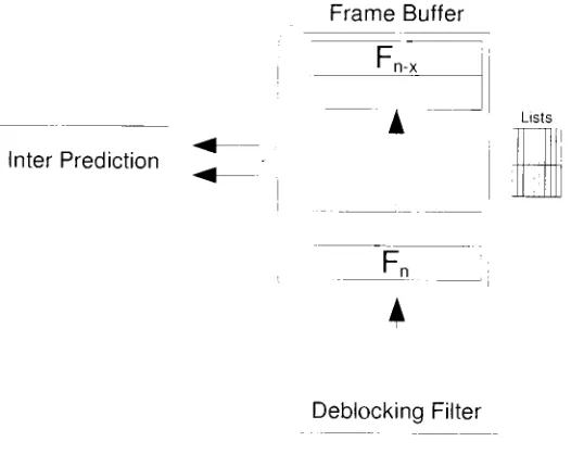
Inter Prediction
Frame Buffer
F
'
Deblocking
Filter [image:40.491.107.370.356.571.2]Lists
Figure 2.12: Organization ofthereferenceframe buffer.
The organization of reference frames within the frame buffer section of the DPB is
shownwithFigure 2.12. Aseachframe is addedto the
buffer,
the sliceheaderinformation
long-term use. Each frame has an index number for
identifying
itself within the framebuffer. Two lists are maintainedbetween
frames,
lists LO and LI. This first list is usedwithbothP-slices and
B-slices,
whereasthe latter is only for B-slices.When
beginning
the addition of a frame to thebuffer,
the current capacity is firstchecked. If the buffer is full then a
"sliding
window"
algorithm is used to discard the
oldest short-term frame. A frame may be marked for long-term storage
by
an explicitmemory storage instruction in the bitstream. Once a frame is marked for long-term stor
age, anexplicitmemory instruction fromthebitstream isrequiredto flush theframeoutof
the buffer.
Oneprocess withinthedecodersystem theInter Prediction
(InterP)
process requiresload access to arbitrary MBs from previously decodedreference frames.
Noting
the slicetypesfrom Table
2.4,
eachindividualmacroblock makes use oftheIntraPorInterPprocess,but not both. This suggests that the
buffering
operations of IntraP and InterP could becombined to overlap intiming.
[21]
2.3.3
Macroblock
pixeltypes.
With additionalpixel types permitted
by
theFRExtamendment, thebinary
size ofa macroblockisrelativeto twoadditionalfactors beyondthepixeldimensionsofthemacroblock
itself: chroma sub-sampling, and sampling depth. The single pixel data size for a set of
Y'CbCr samples is computed
by
the sub-sampling factor times the luma sampling depth.The sub-sampling factor foreach ratio is shown with Table 2.5.
Using
the sub-samplingTable 2.5:
Sub-sampling
factorforall sub-sampling ratios.sub-sampling f:m:n factor
Fss
4:04:2
4:2
4:4 0
0
2
4
1.0 +0.0+0.0= 1.0
1.0 +.25 + .25 = 1.5
1.0 +0.5+0.5 = 2.0
1.0+1.0+ 1.0 = 3.0
factor
Fss,
an equal bit size ofthe lumaand chroma sampleslunrnbits
=thepixel dimensions ofa macroblock
Mw
*Mh,
thebinary
size of a macroblock canbecomputedas such:
MBbits
=(Mw
*Mh)
*(lumablts
*Fss)
(2.4)
Asan example,fora4x4macroblockwith 4:2:0 sub-sampling and 8 bitsofsample
depth,
the
binary
size ofthemacroblockis:MBbits
= (4*4)
*(8
*1.5)
= 192 bits(2.5)
The
binary
sizes of all possible 16x16 macroblocks consideredby
this thesis are detailedwithTable 2.6(a). Asan example ofhowthemacroblock sizeaffectsframestoragecapacity
Table 2.6:
Binary
sizes ofamacroblockandframe.(a) 16x16macroblock,bits chroma sub-sampl
ing
4:0:0 4:2:0 4:2:2 4:4:4 2048 3072 4096 6144 2304 3456 4608 6912 2560 3840 5120 7680 2816 4224 5632 8448 3072 4608 6144 9216
(b) 1080 HDframe,AAbits chromasut>-sampling 4:0:0 4:2:0 4:2:2 4:4:4
1.99 2.99 3.98 5.98 2.24 3.36 4.48 6.72 2.49 3.74 4.98 7.47 2.74 4.11 5.48 8.22 2.99 4.48 5.98 8.96
withinthe
DPB,
Table2.6(b)
details the frame sizes inbits1forthe largest HD-TV resolution: 1080 HD. Note thatwhilethevisible resolution is
1920x1080,
theH.264/AVCcodedluma resolution is actually 1920x1088 due to internal cropping constraints of the codec.
As shown, the largest pixel type produces a 1080 HD frame that is 4.5 times the size of
thesmallest pixel type. Thissignificantvariability in datasize isuniqueto theH.264/AVC
plusFRExtcodec.
Chapter
3
H.264/AVC
Research
This chapter discusses published investigations and conclusions related to
implementing
the frame bufferof an H.264/AVC
decoder,
and also presents several inferences madeby
this thesis.
3.1
Decoder memory
case studies and research.Since its approval in
2003,
the H.264/AVC coding standard[7, 9]
has seen an extensivedegreeofpublishedresearch,
including
theperformance optimization ofbothsoftware andhardware implementations. The extent of open publishing is possibly due to two major
factors.
First,
thebaseline specificationofH.264/AVC is royalty freeand opentoacademiaand
industry
alike without charge beyondpurchasing1
the specification
document,
fromeither ISO or ITU. This is different fromthe preceding MPEG-2 standard, forwhich ISO
charges significant royalties against each implementation [20].
Second,
evenduring
thedrafting
phase, the scalability ofthe standard wasfoundto besuitable forapplicationsbeyondthe original focusof videoconferencing,
including
theup-and-comingtechnology
ofHDTV. H.264/AVC was found to perform well atboth low and high bit rates and resolu
tions [20]. Thesesignificant
factors,
inadditionto others,including industry
and academiatrends, havecontributedto significantpublishing ofH.264/AVCresearch anddevelopment
'Asofearly 2007,ITU-TisnowprovidingfreedownloadoftheentireH.264.X groupofdocumentsand software. Implementations ofprofiles other than Baseline, includingsome ofthe workperformedby this
Encoded VideoDa
H.264/AVC Video Decoder
MacrucnockRow Buffer
ExternalMemory
ExternalMemory Video Driver Dnver
Frame Buffer
//.'//, StreamParser
(Entropy& RunLengthDecoding)
Header Information
^ Prediction
Intra
^_ Prediction
Macroblock
Buffer
Deblocking *"
Filter
Transform Unit
AA
[image:44.491.46.458.67.285.2]Macroblock Row Buffer
Figure 3.1: FPGA hybridon-chip,off-chipdecoderarchitecture proposed in [21].
[24].
In this section, a few supportingworks arediscussed forthe purpose of
depicting
documented approaches to
implementing
theexternal memory ofahardware H.264/AVC decoder withoutFRExt.
3.1.1
Identification
ofmemory
components.Before
discussing
techniques to optimizing memory within the H.264/AVCdecoder,
it isnecessary to first
identify
the memory requirements of the processingblocks,
and also arealistic generic architecture for hardware implementation.
Considering
an FPGA implementationofthe
DPB,
afew distinct independentsections ofbuffering
becomeapparent,asalready detailed in Section 2.3.2. Proposed in
[21]
is a mixedon-chip andoff-chip FPGAmemory architectureforanFPGA
decoder,
asdepictedwithFigure 3.1.From the
figure,
theindependentbuffering
needsofthe decoderare as follows:1. Two ping-pong buffersto FIFO macroblock data between processing stages. These
enough to potentially fit on-chip in FPGA block RAM. One ping-pong buffer is
placed between the stream parser and the transform unit. The other is placed be
tweentheprediction units and the
deblocking
filter.2. A row buffer for data feedback to the intra-prediction unit. For small resolutions,
thisshouldfit on-chip foran FPGA.
However,
for large resolutionsit shouldonly fiton-chip for very large FPGAswitha significantquantityofblock RAM.
3. A row buffer for data feedback to the
deblocking
filter. For small resolutions, thisshould fit on-chip for an FPGA.
However,
for large resolutions it should only fiton-chip for very large FPGAs with a significant quantity of block RAM.
Also,
itis conceivablethat resources are constrainedto only allow instantiation ofone row
bufferon-chip; in such a case, this row buffer can becombined with the reference
frame buffer.
4. Areferenceframe buffer for storingan iV depthof
fully
decoded frames. Thismemory component iscertainto requireamemorycontroller with an externalRAM chip
with a significant capacity.
Each ofthese conceptual
buffering
stages could be combined into a singlebuffering
unitwith off-chip memory, or could be distributed as described. The greater the distribution
ofthememory bufferon-chip, thelowerthebandwidthrequirements oftheexternal RAM
interface.
3.1.2
Optimization
techniques.Custom SDRAMmemorycontrollerfor H.264/AVC.
Oneapproachto optimizingtheframebufferperformanceisto implementacustom mem
ory controller withbus access specifically tailored to theH.264/AVC decoderarchitecture
andframe data. Ratherthanjustoptimizethedata flow logicaroundthememory, themem
comparable dataaccess atlowerclockrates.
Described in
[26],
an HDTV H.264/AVC decoder was implemented with a customSDRAM control for off-chip
buffering
of frame data. First a standard SDRAM memorycontrollerwas usedto control the readand write accesses. Forthe maximumH.264/AVC
Baseline resolution of 1080 HD
(1920x1080),
the clock speed requirement ofthe memory controllerwas determinedto be 193 MHz. The controller was thenreimplemented to
improveperformance.
Reducing
theSDRAMpage-active cyclein 2-dimensionalread andwrite accesses providedaone-third performanceenhancementovertraditionalpageperline
architectures.
Memory
bandwidth was significantly conserved with the additional benefitofincreased
flexibility
withtheimplementation ofotherdecoding
blocks.Specifically,
the clock speed requirement for the the new memory controller was determined to be 121
MHz,
hence an approximate one-third performance improvement ofthe controller. The reduction in clock speed requirement also potentially reduces power
consumption anddevicecost.
Multiplechannelmemoryarchitecture.
Anotherpossible approach,
depending
onthe targetdevice technology, isto usetwomemory controllers with one RAM each for
buffering
different portions offrame data withinthedecoder. In
[10],
an ASIC H.264/AVC decoder architectureutilizes dual memorycontrollerscombinedwith anARM
CPU,
systembus,
andlocal bus. Thearchitecturedemonstrates use oftwobusesandtwomemorycontrollers tofacilitate ahigh levelofcontrolled
parallelism between processing blocks. The performance was sufficient to process real
time 1080HDframes.
Extending
this technique, adeblocking
filter architecture is described in [11]
thatusesa 2-dimensional array ofmemory modules.
Specifically,
the architecture uses eightdual-port SRAM modules,
facilitating
parallel access of eight pixels. The pixels within a4x4macroblock are mappedina linearshift-rotatemanner. Thisallows an
8-way
parallelloadselectconflicts.
Implementable
greedy search algorithmfor frame history.To further increasethehardwareperformance ofthe frame buffer as measured
by
reducing
thenecessaryclock speedandRAM capacity theframe buffer datamanagementmaydiscard an additional quantity offrame data. This form of
lossy
optimization potentiallyincreasesperformance
by
a reduction ofdatatransferacrossthememory busattheexpenseofreducingthe subjective video output quality.
To render the decoded video within
"acceptable"
levels,
an efficient search algorithmmay beusedto determinewhatvideodata ifany-todiscardforeach frame bufferopera
tion. Described in
[5],
the techniqueemploysa greedysearchheuristic todiscard theleastimportant reference frames. In
doing
this, the prediction performance is increased overtheconventional sliding window memory management, which simply discards the oldest
framewithoutasmuch regardtocontext.
Whiletheimplementation complexity ofthis approachis small, thealgorithm requires
experimental
fine-tuning
specific to the decoder architecture,including
the memory accesses.
Additionally,
the subjective video outputquality may becompromisedifthe algorithm is not carefully tuned [5]. Thisapproach is notably ofless general application than
theH.264/AVC-specifiedsliding window algorithm.
Compressedmemorybusaccesses.
Another popular technique foroptimizing decoder power and performance is use ofem
beddedcompression
(EC)
within the memory architecture. All data is compressed with alossless blockcompression algorithmjustpriortomemorystore, anddecompressed imme
diately
following
load frommemory.Considering
that themajorityofdataflowthatutilizesthememoryarchitecturearedecodedmacroblocks, thepotentialsavingsin memorycapac
ity
and data bus operations is significant. The reduction in physical memory operationsDescribed in
[4]
is an EC technique used to optimize a H.264/AVC decoder for realtimeoperationatlowspeedandlowpower consumption. While any formofECwasfound
tobeadequateforreducingthememory capacity requirementsof a generalvideo
decoder,
threemain constraints were determinedaspivotalfor reducingpower consumption:
1. Useablock-basedcompression, and
independently
encode eachblock.2. Seta fixed compression ratio for allblocks and use this fixed ratio for thememory
mapping.
3. Storetheluminance and chrominance planes
jointly
inmemory.3.2
Analysis
of published results.Conjecturing
from the above research, several techniques may be employed to improveexternalmemoryperformance withinavideodecoderwith a singledecoded frame format.
Experimentally
tune the memory controller parameters such that access bursts andthe
topography
of the address mapping are improved specifically for the store andloadofmacroblocks.
Replace the
"sliding
window"algorithm with a more
lossy
algorithm, reducing thetotal number of store and load operations; possibly also reducing the
frequency
ofmemory accesses.
Compress dataasthefirststageofa storeoperation, anddecompress dataasthe final
stage of a load operation, using a lossless block compression algorithm tailed for
Y'CbCr data. This would reduce memory bandwidth and capacity requirements at
theexpenseofadditionalon-chiplogic.
Useadedicated memorycontrollerfortheframe
buffer,
with allintraprediction dataExtrapolating
fromtheaboveresearch,several plausible approachestooptimizing FRExtmemoryperformance include:
Re-sample data as the first stage ofa store operation, and re-sample data as the fi
nal stage of a load operation. This would reduce memory bandwidth and capacity
requirementsattheexpense of additionalon-chip logicandreductionofinterpredic
tionquality.
Configurethe memory mapping anddatapipeline to efficiently handlevariabledata
Chapter
4
Requirements
and
Modeling
This chapter provides an overview ofthe requirements, algorithms anddata flow usedfor
designing
the frame buffer model. The addition of Y'CbCr pixel type variability to theframe buffermodel is alsodiscussed.
4.1
Augmentation
ofdecoder
system.A preexisting Baseline H.264/AVC decoder testbench system was obtained from [21].
Whilemuch ofthe
functionality
oftheH.264/AVC Baselineprofile wasimplemented,
thesystemwasonlycapable o
![Figure 2.6: Scope of H.264/AVC Standard: only decoding [24].](https://thumb-us.123doks.com/thumbv2/123dok_us/61289.5703/32.491.123.370.297.409/figure-scope-h-avc-standard-decoding.webp)
![Figure 2.9: Buffering within the H.264/AVC Hypothetical Reference Decoder. [9]](https://thumb-us.123doks.com/thumbv2/123dok_us/61289.5703/38.491.81.403.57.257/figure-buffering-h-avc-hypothetical-reference-decoder.webp)
![Figure 3.1: FPGA hybrid on-chip, off-chip decoder architecture proposed in [21].](https://thumb-us.123doks.com/thumbv2/123dok_us/61289.5703/44.491.46.458.67.285/figure-fpga-hybrid-chip-chip-decoder-architecture-proposed.webp)