Int. J. Electrochem. Sci., 13 (2018) 8006 – 8021, doi: 10.20964/2018.08.07
International Journal of
ELECTROCHEMICAL
SCIENCE
www.electrochemsci.org
An Efficient Carbon Coating Process Applied in Different
Synthetic Routes of LiFePO
4Cathode Materials
Guan Wu, Tingting Jiang, Xiaohui Tian, Yanbin Zhu, Yingke Zhou*
The State Key Laboratory of Refractories and Metallurgy, Institute of Advanced Materials and
Nanotechnology, College of Materials and Metallurgy, Wuhan University of Science and Technology, Wuhan 430081, China
*
E-mail: [email protected]
Received: 22 March 2018 / Accepted: 20 May 2018 / Published: 5 July 2018
Four LiFePO4/C composites have been successfully synthesized via Fe2O3 route, FeC2O4 route, FePO4
route in solid-state method and FeSO4 route in hydrothermal method with an efficient carbon coating
process which innovatively employed compound carbon sources that consisted of fructose and calcium lignosulfonate. Kilogram grade pilot samples have been prepared and 2000 mAh pouch cells have been assembled and investigated. Due to the introduction of fructose and calcium lignosulfonate, the as-prepared LiFePO4/C composites possess a layer of conductive carbon that contains calcium compound
on the surface of LiFePO4 particles, which are supposed to improve the electronic conductivity and
reduce the side reaction between LiFePO4 and electrolytes. All of the as-prepared LiFePO4/C
composites show different characteristics in full cells, the capacity retention of Fe2O3 derived LFP-S1
was as high as 92.2% after 400 days storage, the capacity retention of FeC2O4 derived LFP-S2 at 5C
rate was 93.0%, the capacity retention of FePO4 derived LFP-S3 at -20 ℃ was 66.7%, the capacity
retention of FeSO4 derived LFP-S4 was as high as 90.2% after 3000 cycles at 25 ℃.
Keywords: LiFePO4; carbon coating; solid-state; Hydrothermal; Lithium-ion batteries
1. INTRODUCTION
LiFePO4, LiMn2O4 and LiNixCoyMn1-x-yO2 materials. For LiMn2O4 cathode materials, due to the
“Jahn-Teller” effect of Mn3+
lead to serious dissolution of Mn element, LiMn2O4 cathode suffers from
poor cycling performance at high temperature [5]. For LiNixCoyMn1-x-yO2 cathode materials, the
layered structure was unstable, which directly resulted in poor thermal stability and safety problems of LiNixCoyMn1-x-yO2 materials [6]. On the other hand, LiFePO4 cathode presents many advantages such
as the relatively high theoretical capacity (170 mAh g-1), proper charge-discharge potential (~3.4 V versus Li+/Li), low cost, environmental-friendly, excellent cycle life and structural stability [7]. The olivine structured lithium iron phosphate (LiFePO4) has been widely researched since reported as a
promising cathode material for lithium-ion batteries by Padhi et al. in 1997 [8]. Nevertheless, the intrinsic low lithium-ion diffusion and electronic conductivity directly lead to the poor rate capability and capacity loss, which are bottlenecks for the wide application of LiFePO4 cathode [9,10].
Many efforts have been made to overcome the electronic and ionic transport limitations of LiFePO4, including optimizing the size and morphology, doping with alien atoms, and coating with
conductive carbon materials [5,11-13]. Among these strategies, the carbon coating is one of the most conventional methods to promote the specific capacity and rate performance by offering more routes for electron transfer and accelerating the transport of lithium ion. An efficient carbon coating technology plays an essential role in the manufacturing process of commercialized LiFePO4 materials
[14,15]. Various methods, such as solid-state reaction, hydrothermal/solvothermal synthesis, co-precipitation, sol-gel processing, microwave assisted synthesis, and spray pyrolysis, have been applied to synthesize the LiFePO4/C composites [16-18]. The solid-state method is the most common
technique to synthesize LiFePO4/C materials in industrial production since it is facile to operate and
easy for magnification. Fe2O3, FeC2O4 and FePO4 are the main raw materials to provide the Fe source
in the industrial solid-state production, and LiFePO4/C products derived from different routes usually
present different characteristics [19-23]. Besides, the hydrothermal method is also employed in industrial production due to it can make the morphology and particle size of LiFePO4 controllable,
FeSO4 is commonly used as the raw material and the LiFePO4/C products with controllable
morphology and outstanding performances are usually obtained [24-27].
In this work, a mixture of carbon sources consisting of fructose and calcium lignosulfonate has been employed to form the carbon coating layer on the surface of LiFePO4 particles, by using the
solid-state method with respectively Fe2O3, FeC2O4, and FePO4 as the Fe source, and hydrothermal
method with FeSO4 as the Fe source. Various characterizations and electrochemical tests have been
carried out to investigate the impacts of different synthetic routes on the carbon coating process and the corresponding performances. Kilogram grade pilot samples have been prepared and 2000 mAh pouch cells have been assembled and investigated. The rate performances, low temperature performances, long term cycle performances and storage performances of the samples have been systematically tested. Due to the introduction of fructose and calcium lignosulfonate, the as-prepared LiFePO4/C composites possess a coating layer of conductive calcium doped carbon, which are
supposed to improve the electronic conductivity and reduce the side reaction between LiFePO4 and
electrolytes. Four as-prepared LiFePO4/C composites show different characteristics. Among different
synthetic routes of solid-state method, the sample derived from Fe2O3 route shows better storage
derived from FePO4 route displays greatly improved cycle performance and higher capacity retention
at low temperature. The LiFePO4/C materials derived from the hydrothermal FeSO4 route display
excellent overall electrochemical performances and thermal stability. Form these characteristics of the obtained samples, the raw materials and synthesis routes can be selected to prepare suitable LiFePO4/C
composite materials with featured performances and suitable for different terminal applications.
2. EXPERIMENTAL
2.1 Preparation of materials
The LiFePO4/C composites were prepared by the Fe2O3 route, FeC2O4 route, FePO4 route with
solid-state method and the FeSO4 route with hydrothermal method, respectively. The synthesis
procedures of Fe2O3 route were described as follows. Fe2O3 (≥ 99.5 wt%), Li2CO3 (≥99.5 wt%),
LiH2PO4 (≥ 99.0 wt%), fructose (≥ 99.5 wt%), and calcium lignosulfonate (≥ 97.0 wt%) were used as
starting materials, and the molar ratio of Li:Fe:P was controlled to be 1.03 : 0.97 : 1. The Fe2O3,
LiH2PO4 and a small amount of fructosewere successively added into a bead mill machine and ethanol
was used as the solvent. Li2CO3 was added to adjust the Li content. After grinding, the fluidic mixture
was dried by a spray drying process, annealed at 790 ℃ for 6 h in N2 atmosphere and pulverized
through a jet milling process. After that, the intermediate product was mixed with the rest of fructose and calcium lignosulfonate in the same bead mill machine to achieve adequate grinding, and then spray dried, annealed at 750℃ for 8 h in N2 atmosphere, and jet milled to obtain the final LiFePO4/C
composites. The sample was named LFP-S1 in the following description.
The sample derived from FeC2O4 route was prepared as follows. FeC2O4 (≥ 99.5 wt%), Li2CO3
(≥ 99.5 wt%), NH4H2PO4 (≥ 99.5 wt%), fructose (≥ 99.5 wt%), and calcium lignosulfonate (≥ 97.0
wt%) were used as raw materials, and the molar ratio of Li:Fe:P was controlled to be 1.03 : 0.97 : 1. The FeC2O4, Li2CO3, NH4H2PO4 and a small amount of fructosewere added into a bead mill machine
in sequence, and ethanol was used as the solvent. After grinding, the fluidic mixture was dried by a spray drying process, annealed at 680 ℃ for 4 h in N2 atmosphere and pulverized through a jet milling
process. After that, the intermediate product was mixed with the rest of fructose and calcium lignosulfonate in the same bead milling machine to achieve adequate grinding, then spray dried, annealed at 720 ℃ for 8 h in N2 atmosphere, and jet milled again to obtain the final LiFePO4/C
composites. The sample was named LFP-S2 in the following descriptions.
The sample derived from FePO4 route was prepared as follows. FePO4 (≥99.5 wt%), Li2CO3 (≥
99.5 wt%), fructose (≥ 99.5 wt%), and calcium lignosulfonate (≥ 97.0 wt%) were used as raw materials, the molar ratio of Fe:P in the FePO4 raw material was 0.97: 1, and the molar ratio of Li:Fe:P
was controlled to be 1.03 : 0.97 : 1. The FePO4, Li2CO3, fructose and calcium lignosulfonatewere
process the LiFePO4/C materials were obtained. The sample was named LFP-S3 in the following
descriptions.
For the hydrothermal method, the sample was synthesized as follows. LiOH·H2O (> 99.5 wt%),
FeSO4·7H2O (> 99.5 wt%), H3PO4 (85 wt%) were used as raw materials, deionized water was used as
the solvent. The LiOH solution and H3PO4 were firstly added into an autoclave under stirring to obtain
a white suspension, and then the FeSO4 solution and a proper amount of ascorbic acid were added. The
molar ratio of Li:Fe:P was controlled to be 2.7: 0.97: 1 in the precursor solution. After that, the autoclave was sealed and heated to 180 ℃ and maintained for 6 h, then the obtained precipitates were washed with deionized water for several times. Then the precipitates were added into a solution with fructose and calcium lignosulfonate with stirring to form a well-distributed suspension, which was then dried by spray drying, annealed at 700 ℃ for 6 h in N2 atmosphere and pulverized through a jet milling
process to obtain the LiFePO4/C composites. The sample was named LFP-S4 in the following
descriptions.
2.2 Characterization
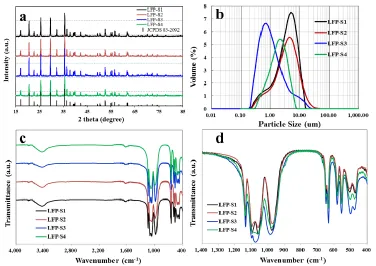
The crystal structures of all samples were identified by X-ray diffraction (XRD) using a Bruker D8 X-ray diffractometer with Cu Kα radiation, and the experimental diffraction patterns were collected
by step scanning in the range of 15 ° ≤ 2θ ≤ 85 °. Fourier transform infrared spectra (FTIR) of the materials were recorded from 4000 to 400 cm−1 by a Frontier FTIR spectrometer using the KBr pellet method. The particle distribution was confirmed by the Malvern Master Size 2000 analyzer. The Brunauer-Emmett-Teller (BET) method was performed to calculate the specific surface area using a TriStarⅡ3020 analyzer. The carbon content was confirmed by a HCS-140 high frequency infrared carbon and sulfur analyzer (Dekai, Shanghai). The morphology of the samples was investigated by the ZEISS Sigma-02-33 scanning electron microscopy (SEM). The fine structure of the samples was examined by field emission FEI F20 transmission electron microscopy (TEM). The thermal stability of the samples was tested by a Netzsch STA449F3-QMS403C analyzer using differential scanning calorimetry (DSC) method. The coin cells were charged to 3.8 V before the cathode powder was scraped off the electrode to react with electrolyte, and the examination was performed over the range from 50 to 450 ℃ with a heating rate of 10 ℃/min
2.3 Electrochemical measurements
Electrochemical performances of the samples were tested with coin shaped half cells. The metallic lithium film was used as the counter and reference electrode. The liquid electrolyte is a solution of 1 M LiPF6 in ethylene carbonate (EC)-ethyl methyl carbonate (EMC)-diethyl carbonate
an Ar filled glove box. The charge and discharge tests were performed over the voltage range of 2.0-3.8 V using a Land BTS-5V-50mA computer-controlled battery test station. CV tests were conducted over the voltage range between 2.0 and 4.2 V using a Bio-Logic VMP3B electrochemical workstation at the scanning rate of 0.1 mV s-1, and EIS measurements were performed over the frequency range between 1 MHz and 100 mHz by using a ZAHNER Im6ex electrochemical workstation with an applied perturbation signal of 5 mV.
For further analysis of the practical performance, the pouch shaped full cells of all samples with a 2000 mAh rated capacity were fabricated. Commercialized graphite was employed as the anode. 94 wt% cathode materials, 2 wt% conductive carbon Super P and 4 wt% polyvinylidene fluoride (PVDF) binder were thoroughly mixed in N-methyl pyrrolidinone (NMP) and then pasted onto aluminum foil (16 μm) to perform as the cathode. The rate performances were tested over the voltage range of 2.0-3.65 V by a Neware 5V30A battery test station. The capacity retention at 0.5 C and the cyclic performances at 1 C at different temperatures were performed on the same Neware 5V30A battery test station connected with thermostats. The storage performances at 25 and 60 ℃ with a state of charge (SOC) of 100% at 0.5 C were also performed on the Neware 5V30A battery test station connected with thermostats.
3. RESULTS AND DISCUSSION
[image:5.596.110.486.413.679.2]
Table 1. The particle size distribution parameters, specific surface area and carbon content of four LFP samples.
Volume particle size (μm) Specific surface area (m2/g)
Carbon content (%)
D10 D50 D90 D99
LFP-S1 0.81 3.60 8.20 11.90 14.2 2.07
LFP-S2 0.83 3.58 9.50 20.10 16.7 1.85
LFP-S3 0.35 0.85 3.80 13.10 13.7 1.87
LFP-S4 0.68 1.81 3.92 5.91 15.6 1.91
The mixture of fructose and calcium lignosulfonate was used as carbon sources for the Fe2O3
route, FeC2O4 route, FePO4 route in solid-state method and the FeSO4 route in hydrothermal method,
and finally the carbon coated composites of LFP-S1, LFP-S2, LFP-S3 and LFP-S4 were respectively obtained. All of the LiFePO4/C composites were systematically characterized by various techniques.
Figure 2. Typical SEM images: (a) LFP-S1, (b) LFP-S2, (c) LFP-S3, (d) LFP-S4.
[image:7.596.166.433.344.698.2]
Different peak intensities might be attributed to the different combination status between the residual organic functional groups and the carbon coating layer, which effected by the different superficial smoothness of LiFePO4 particles. According to the principle of “like dissolves like”, these
residual active functional groups on the surface of LiFePO4 particles are expected to improve the
infiltration between cathode and electrolytes, which was supposed to accelerate the insertion/extraction reactions of lithium ions and enhance the electrochemical rate performances [32,33].
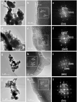
The typical SEM images of LFP-S1, LFP-S2, LFP-S3 and LFP-S4 are displayed in Fig.2a to Fig.2d, respectively. No redundant residual carbon can be found on the particle surface of all the samples, indicating the high efficiency of the carbon coating process with the introduction of the mixture of fructose and calcium lignosulfonate. For the Fe2O3 route derived LFP-S1 powder, the
primary particle size is in the range of 100 to 500 nm, but aggregations clearly occur due to the high sintering temperature. For the LFP-S2 sample synthesized by the FeC2O4 route, the particles are more
[image:8.596.172.423.345.626.2]uniform and the primary particle size is mainly between 150 to 200 nm, the small and uniform particles usually corresponding to short average distance for the insertion/extraction process of lithium ions.
Figure 4. Discharge curves at different rates of (a) LFP-S1, (b) LFP-S2, (c) LFP-S3, (d) LFP-S4; (e) Comparison of the first discharge curves; (f) Comparison of cycling performances.
The primary particle size of LFP-S3 is about 200~400 nm, with a few large-sized particles. As FePO4 is employed as the precursor, the morphology and particle size of LFP-S3 are easily affected by
the applied FePO4 raw material. For the LFP-S4 sample derived from the hydrothermal FeSO4 route,
coating and tight integration between LiFePO4 particles and the pyrolytic carbon from fructose and
calcium lignosulfonate.
TEM measurements were performed to investigate the status of the carbon layer and the differences of crystal structure of the LiFePO4 materials derived from different synthesis routes.
Typical TEM images and the corresponding electron diffraction patterns of the samples are exhibited in Fig.3.
As shown in Fig.3a-c, small particles (~150 nm) and large particles (>500 nm) are simultaneously appeared in the LFP-S1 sample, the thickness of the carbon layer was about 2 nm to 4 nm. The (01-1) and (211) planes of olivine structures can be clearly identified along the [-111] axis in the corresponding electron diffraction pattern, which is consistent with the results of high resolution TEM image. TEM images of LFP-S2 are shown in Fig.3d-f, where the pyrolytic carbon layer with the thickness of ~4 nm is observed in the high resolution TEM image, and the (30-1) and (311) planes are found along the [-16-3] axis in the electron diffraction pattern. As shown in Fig.3g-i, the morphology of LFP-S3 is consistent with the SEM results, and clear lattice fringes are observed. The thickness of the coating carbon layer is about 4 to 6 nm, and the (020) and (200) planes of olivine structures are identified along the [001] zone axis. Typical TEM images and the corresponding electron diffraction pattern of LFP-S4 are shown in Fig.3j-l, where rod-like particles coated with a thin layer of carbon of ~3 nm are observed. Clear lattice fringes corresponding to the (11-1) and (211) planes are clearly observed along the [-231] axis in the high resolution image and confirmed in the electron diffraction patterns. The carbon layers of all the four samples are integrally coated on the surface of LiFePO4
particles, indicating that the carbon coating processes employed here are highly efficient [34,35]. A small amount of calcium compounds was supposed to form on the surface of the LiFePO4 particles as
the calcium element introduced by calcium lignosulfonate, which may favor the surface stabilization. The differences of crystal structure of the four LiFePO4/C composites derived from different synthesis
routes are mainly ascribed to the different raw materials and synthesis conditions.
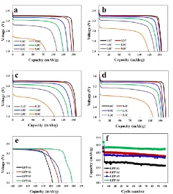
The electrochemical charge and discharge tests of the samples were performed over the voltage range of 2.0-3.8 V in coin cells. Shown in Fig.4a-d are the discharge curves of S1, S2, S3 and S4 at different rates from 0.1 C to 5 C. The discharge specific capacities of S1, LFP-S2, LFP-S3 and LFP-S4 are respectively 151.2, 155.3, 157.2 and 164.0 mAhg-1 at 0.1 C, and are respectively 82.2, 123.5, 104.0 and 132.7 mAhg-1 at 5 C. The LFP-S4 sample derived from the FeSO4
route displays the highest specific capacity among the as-synthesized materials, probably ascribed to the excellent crystalline and uniform morphology with the hydrothermal method. Among the samples synthesized by the solid-state method, LFP-S3 derived from the FePO4 route displays higher specific
capacity than LFP-S1 and LFP-S2 at low rates of 0.1 and 0.2 C. However, at higher discharge rates, the LFP-S2 sample produced by the FeC2O4 route shows obvious advantages than S1 and
LFP-S3. The higher specific capacity of LFP-S2 at high rates may result from the more uniform particles and smaller particle size with FeC2O4 in the solid-state synthesis. The magnified first discharge curves
discharge curve is much lower than that of LFP-S2, indicating the higher polarization of the LFP-S3 sample.
The charge/discharge tests were performed at 0.5 C for 100 times after activated the coin cells at 0.1 C for 2 cycles, and the cyclic curves of all the samples are shown in Fig.4f. After cycled for 100 times in coin cells, the capacity retention of LFP-S1, LFP-S2, LFP-S3 and LFP-S4 is 96.5%, 96.7%, 97.3% and 98.7%, respectively.
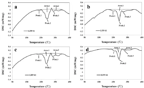
In order to confirm the thermal stability of the samples, the differential scanning calorimetry measurements (DSC) have been performed after charging the coin cells to 3.8 V. The DSC curves of LFP-S1, LFP-S2, LFP-S3 and LFP-S4 are respectively exhibited in Fig.5a-d. According to the DSC curves, the exothermic peaks and the corresponding areas can be respectively ascribed to the temperature of thermal runaway and the amount of released heat, which are originated from the reaction between the cathode and electrolyte [36]. The start temperatures of thermal runaway are 236.9, 252.3, 233.1 and 257.8 ℃ for LFP-S1, LFP-S2, LFP-S3 and LFP-S4, respectively. The total amounts of released heat of these four samples are 113.3, 117.9, 144.8 and 110.4 J/g, respectively. All the samples release a low amount of heat during the DSC tests, indicating the good thermal stability and high safety of the as-synthesized LiFePO4/C composites with the carbon sources of fructose and
calcium lignosulfonate. The overall thermal stability of LFP-S2 and LFP-S4 derived from the FeC2O4
route and FeSO4 route are better than that of LFP-S1 and LFP-S3, probably attributed to the more
[image:10.596.63.528.421.704.2]uniform morphology and higher crystalline structure of LFP-S2 and LFP-S4.
Figure 6. EIS curves of four samples: (a) 25 ℃, (b) 0 ℃; (c) Comparison of cyclic voltammetry results of four samples.
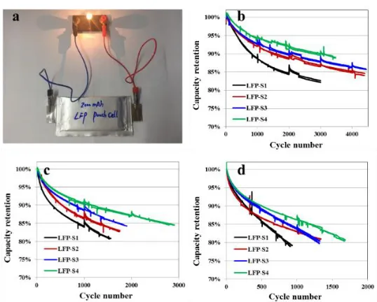
[image:11.596.142.450.70.283.2]Figure 7. (a) Typical digital photo showing a lamp bulb is powered on with the LFP full cell; Comparison of the long-term cycling curves: (b) 25 ℃, (c) 45 ℃, (d) 60 ℃.
[image:11.596.163.432.339.555.2] [image:11.596.152.444.612.724.2][image:12.596.145.448.284.646.2]
The kinetic behaviors of the samples were further studied by EIS and CV measurements in coin cells. The EIS curves of all four samples at 25 and 0 ℃ are presented in Fig.6a and b, respectively. The charge transfer resistance of LFP-S1, LFP-S2, LFP-S3 and LFP-S4 at 25 ℃ is about 140, 50, 60 and 35 Ω, respectively. At low temperature, the LFP-S4 still displayed the lowest charge transfer resistance among four as-prepared samples, indicating the lowest polarization of LFP-S4. The cyclic voltammograms of the samples were measured over the voltage range of 2.0-4.2 V at the scan rate of 0.1 mV s-1, as shown in Fig.6c. The LFP-S1 sample displays the broadest redox peaks among the four as-synthesized materials, which reveals obvious polarization of LFP-S1. The redox peaks of LFP-S2 are sharper than that of LFP-S3, and the voltage gap between the redox peaks of LFP-S4 is smaller than that of the other three samples. These results indicate that the LFP-S4 sample presents the highest kinetics, and LFP-S2 exhibits lower polarization than LFP-S3. Lower polarization is associated to higher reversibility and rate performances during the lithium insertion and extraction process [37,38].
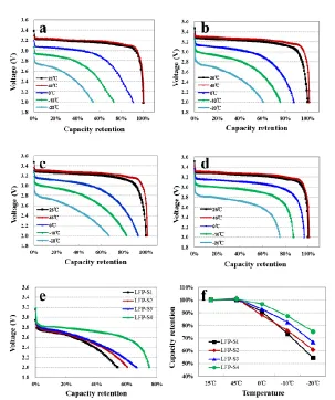
Figure 9. Discharge curves of the full cells at different temperatures: (a) S1, (b) S2, (c) LFP-S3, (d) LFP-S4; (e) Comparison of the discharge curves at -20 ℃; (f) Comparison of the capacity retention at different temperatures.
electrochemical performances in practical application. Fig.7a displays a typical photo of a full cell powering a lamp bulb.
The long-term cycle tests of the full cells that respectively employed four as-prepared samples as cathode were conducted at the charge/discharge rate of 1 C. The results at different temperatures of 25, 45 and 60 ℃ are shown in Fig.7b-d respectively. Because of the efficient carbon coating process employed in this work, all four samples show acceptable cycle performances which can be utilized in various markets with different requirements. The LFP-S4 sample derived from the FeSO4 route
displays better cycle ability than that other three samples before the capacity retention fading to 80%, which is regarded as the failpoint of full cells in practical application. During the cycling at 25 and 45 ℃, the capacity retention of LFP-S2 derived from the FeC2O4 route is lower than that of LFP-S3
derived from the FePO4 route. However, when cycling at 60 ℃, the capacity retention of LFP-S2
exceeds that of LFP-S3 after 1100 cycles, indicating the better durability of LFP-S2 at high temperature cycling, that may mainly because of the more uniform particles and smooth surfaces of LFP-S2 sample benefits the structural stability at high temperature.
The long-term storage performances of all four samples were tested after the cells were full charged, the storage curves at 25 and 60 ℃ are respectively displayed in Fig.8a and b. The LFP-S2 sample shows the lowest capacity retention during storage, which mainly ascribed to the highest specific surface area as which leads to more side effects between the particles and electrolyte, and accelerating the speed of capacity fading. The storage performance of LFP-S1 is slightly lower than that of S4 at 25 ℃. But after storage at 60 ℃ for about 100 days, the capacity retention of LFP-S1 exceeds that of LFP-S4. The advantage of LFP-LFP-S1 in high temperature storage is supposed to enlarge as the storage process continues. The featured durable storage performance of the LFP-S1 sample that derived from the Fe2O3 route is mainly because of the LFP-S1 material was originated
from a higher calcination temperature that helps to break the Fe-O bond of Fe2O3 and finally achieved
a more stable intrinsic crystalline structure.
The full cells of all LiFePO4/C samples were tested at different temperatures to investigate the
operational capability in different working conditions. The discharge curves of S1, S2, LFP-S3 and LFP-S4 at temperature of -20 to 45 ℃ are respectively displayed in Fig.9a-d. The discharge curves of the four samples at -20 ℃ are shown in Fig.9e to compare the discharge ability of the cells at low temperatures. Fig.9f is the overall comparison of the capacity retention of the four samples at different temperatures. The discharge voltage plateau of LFP-S1 is a little lower than that of the other samples, especially at 25 and 45 ℃, indicating the higher polarization brought by the Fe2O3 route. The
capacity retention of LFP-S1, LFP-S2, LFP-S3 and LFP-S4 at -20 ℃ is 54.2%, 60.7%, 66.7% and 75.1%, respectively. The LFP-S4 sample shows the best discharge ability at low temperature, and the capacity retention of LFP-S3 at -10 and -20 ℃ is higher than that of LFP-S1 and LFP-S2. This may mainly due to the similar crystalline structure of FePO4 and LiFePO4 which resulted in the FePO4 route
Figure 10. Discharge curves of the full cells at different rates: (a) LFP-S1, (b) LFP-S2, (c) LFP-S3, (d) LFP-S4.
The discharge curves of LFP-S1, LFP-S2, LFP-S3 and LFP-S4 at 0.5 to 5 C are respectively shown in Fig.10a-d to compare the rate performances. All four samples present rather high capacity retention at high discharge rates due to the high quality and conductivity of the carbon coating layer. The capacity retention of LFP-S1, LFP-S2, LFP-S3 and LFP-S4 is respectively 96.8%, 99.3%, 91.8% and 98.2% at 3 C, and respectively 88.9%, 93.0%, 92.2% and 95.9% at 5 C rate. The LFP-S2 sample from the FeC2O4 route displays the highest discharge capacity retention at 0.5 to 3 C, and the LFP-S4
sample from the FeSO4 route shows the highest discharge capacity retention at 5 C. The better
discharge ability of LFP-S2 and LFP-S4 at high rate is mainly attributed to the uniform morphology and nanoscale structure, which shorten the distance and accelerated the speed of Li+ insertion/extraction process in LiFePO4 particles.
As mentioned above, the solid-state reaction is the most facile method to obtain LiFePO4
materials in mass production. The Fe2O3 route, FeC2O4 route and FePO4 route are most commonly
applied in the solid-state synthesis [5, 15-19]. For the LFP-S1 material obtained from the Fe2O3 route
in this work, the prime cost is the lowest due to the cheapness of the Fe2O3 raw material. The LFP-S1
material displays acceptable overall electrochemical performances and outstanding storage performances, which is appropriate for utilizations in the market of energy storage system with strict requirements on the cost and long-term storage performances.
The LFP-S2 material synthesized by the FeC2O4 route is composed of nano-scaled particles and
The LFP-S3 material displays remarkable processability, high specific capacity and reasonably well low temperature performances, and the corresponding FePO4 route is facile for the high-volume
production because of its simple one-step process and relatively low cost. Therefore, the LFP-S3 material is qualified for the market of electric buses where large quantity of activematerials with stable production process are rigidly demanded.
Although the solution based synthesis is usually related to more complicated procedures and facilities and higher cost of production, it is more advantageous to control the crystal growth, morphology and particle size of LiFePO4 materials [22,31]. The solution based hydrothermal method
has been applied to the mass production of LiFePO4 in recent years. The LFP-S4 material originated
from the hydrothermal FeSO4 route presents high specific capacity, high thermal stability and safety,
and superiority long-term cycling performance and low temperature performance. Therefore, the LiFePO4/Cproducts synthesized by the FeSO4 route in this work are suitable for applications in the
high-end electric automobiles and devices that require high energy density and long service time but with high tolerance to cost.
4. CONCLUSIONS
Herein, LiFePO4/C composites have been successfully synthesized by the solid-state Fe2O3
route, FeC2O4 route, FePO4 route and the hydrothermal FeSO4 route, with an efficient carbon coating
process using the dual carbon sources of fructose and calcium lignosulfonate. All of the prepared LiFePO4/C samples are coated by a thin layer of continuous carbon with high conductivity. The
residual pyrolytic carbon layer contains a certain amount of organic functional groups introduced by the fructose and calcium lignosulfonate. These active functional groups assist to improve the reactivity of cathode and the infiltration between cathode and electrolytes. Besides, a small quantity of calcium compounds formed on the surface of LiFePO4 particles which favor the surface stability and depress
the side reaction between LiFePO4 and electrolytes. Therefore, the efficient carbon coating technology
introduced in this work enables the excellent overall electrochemical performances of all the as-synthesized LiFePO4/C samples. Depending on the different procedures, the synthesized materials
exhibit different features and can be promisingly applied as the potential cathode for lithium-ion batteries.
ACKNOWLEDGEMENTS
This work was supported by the National Natural Science Foundation of China (No. 51372178) and the Natural Science Foundation for Distinguished Young Scholars of Hubei Province of China (No. 2013CFA021).
References
1. Y.H. Huang, J.B. Goodenough, Chem. Mater., 20 (2016) 7237. 2. M.S. Whittingham, Chem. Rev., 104 (2004) 4271.
4. K.X. Wang, X.H. Li, J.S. Chen, Adv. Mater., 27 (2015) 527.
5. D.K. Kim, P. Muralidharan, H.W. Lee, R. Ruffo, Y. Yang, C.K. Chan, H.L. Peng, R.A. Huggins, Y Cui, Nano Lett., 8 (2008) 3948.
6. H. Kaneda, Y. Koshika, T. Nakamura, H. Nagata, R. Ushio, K. Mori, Int. J. Electrochem. Sci., 12 (2017) 4640.
7. H.C. Kang, D.K. Jun, B. Jin, E.M. Jin, K.H. Park, H.B. Gu, J. Power Sources, 179 (2008) 340. 8. A.K. Padhi, K.S. Nanjundaswamy, J.B. Goodenough, J. Electrochem. Soc., 144 (1997) 1188. 9. J. Lu, Z.H. Chen, Z.F. Ma, F. Pan, L.A. Curtiss, K. Amine, Nat. Nanotechnol., 11 (2016) 1031. 10. Y.K. Zhou, J. Wang, Y.Y. Hu, R. O’Hayre, Z.P. Shao, Chem. Commun. 46 (2010) 7151. 11. A.V. Murugan, T. Muraliganth, A. Manthiram, J. Phys. Chem. C, 112 (2008) 46.
12. G. Wu, R. Ran, B. Zhao, Y.J. Sha, C. Su, Y.K. Zhou, Z.P. Shao, J. Energy Chem., 23 (2014) 363. 13. L.H. Hu, F.Y. Wu, C.T. Lin, A.N. Khlobystov, L.J. Li, Nat. Commun., 4 (2013) 1687.
14. G. Wu, Y.K. Zhou, Z.P. Shao, Appl. Surf. Sci., 283 (2013) 999. 15. R.R. Chen, Y.X. Wu, X.Y. Kong, J. Power Sources, 258 (2014) 246.
16. H. Kim, H. Kim, S.W. Kim, K.Y. Park, J. Kim, S. Jeon, K. Kang, Carbon, 50 (2012) 1966. 17. W. Wei, P. Qu, M.T. Xu, X.Y. Qiu, L.L. Guo, L. Guo, Rsc Adv., 5 (2015) 37830.
18. K. Dokko, S. Koizumi, H. Nakano, K. Kanamura, J. Mater. Chem., 17 (2007) 4803. 19. A. Yamada, S. C. Chung, K. Hinokuma, J. Electrochem. Soc., 148 (2001) A224.
20. L. Laffont, C. Delacourt, P. Gibot, M.Y. Wu, P. Kooyman, C. Masquelier, Chem. Mater., 18 (2014) 5520.
21. Z.H. Chen, J.R. Dahn, J. Electrochem. Soc., 149 (2002) A1184.
22. X.L. Wu, L.Y. Jiang, F.F. Cao, Y.G. Guo, L.J. Wan, Adv. Mater., 21 (2009) 2710. 23. P.P. Prosini, D. Zane, M. Pasquali, Electrochim. Acta, 46 (2001) 3517.
24. S.S. Zhang, J.L. Allen, K.Xu, T.R. Jow, J. Power Sources, 147 (2005) 234.
25. K. Dokko, S. Koizumi, K. Sharaishi, K. Kanamura, J. Power Sources, 165 (2007) 656.
26. G. Meligrana, C. Gerbaldi, A. Tuel, S. Bodoardo, N. Penazzi, J. Power Sources, 160 (2006) 516. 27. J. Qian, M. Zhou, Y. Cao, X. Ai, H. Yang, J. Phys. Chem. C, 114 (2010) 3477.
28. K. Shiraishi, K. Dokko, K. Kanamura, J. Power Sources, 146 (2005) 555. 29. B. Jin, H.B. Gu, Solid State Ionics, 178 (2008) 1907.
30. B. Scrosati, J. Hassoun, Y.K. Sun, Energy Environ. Sci., 4 (2011) 3287.
31. H. Liu, C. Li, H.P. Zhang, L.J. Fu, Y.P. Wu, H.Q. Wu, J. Power Sources, 159 (2006) 717. 32. Y.W. Chen, J.S. Chen, Int. J. Electrochem. Sci., 7 (2012) 8128.
33. Z. Ma, G. Shao, G. Wang, J. Du, Z. Ying, Ionics, 19 (2013) 437.
34. A. Liu, Y. Liu, Z. Hu, G. Gao, Y. Xu, L. Lei, J. Phys. Chem. Solids, 72 (2011) 831. 35. S. Yoo, B. Kang, J. Mater. Chem. A, 3 (2015) 13906.
36. S.W. Zhu, M.X. Jing, Z.C. Pi, L.L. Chen, X.Q. Shen, Int. J. Electrochem. Sci., 10 (2015) 10597. 37. Y. Koyama, T. Uyama, Y. Orikasa, T. Naka, H. Komatsu, K. Shimoda, H. Murayama, K. Fukuda,
H. Arai, E. Matsubara, Y. Uchimoto, Z. Ogumi, Chem. Mater., 29 (2017) 2855. 38. P.H. Xiao, G. Henkelman, ACS Nano, 12 (2018) 844.