concentrically braced frames.
White Rose Research Online URL for this paper: http://eprints.whiterose.ac.uk/85512/
Version: Accepted Version
Article:
Jazany, R.A., Hajirasouliha, I. and Farshchi, H. (2013) Influence of masonry infill on the seismic performance of concentrically braced frames. Journal of Constructional Steel Research, 88. 150 - 163. ISSN 0143-974X
https://doi.org/10.1016/j.jcsr.2013.05.009
[email protected] https://eprints.whiterose.ac.uk/ Reuse
Unless indicated otherwise, fulltext items are protected by copyright with all rights reserved. The copyright exception in section 29 of the Copyright, Designs and Patents Act 1988 allows the making of a single copy solely for the purpose of non-commercial research or private study within the limits of fair dealing. The publisher or other rights-holder may allow further reproduction and re-use of this version - refer to the White Rose Research Online record for this item. Where records identify the publisher as the copyright holder, users can verify any specific terms of use on the publisher’s website.
Takedown
If you consider content in White Rose Research Online to be in breach of UK law, please notify us by
Influence of Masonry Infill on the Seismic Performance of
Concentrically Braced Frames
Roohollah Ahmady Jazany1, Iman Hajirasouliha2*, Hamidreza Farshchi1
1
International Institute of Earthquake Engineering and Seismology, Tehran, Iran 2
Department of Civil and Structural Engineering, The University of Sheffield, Sheffield, UK *
Corresponding author; E-mail:[email protected]
Tel:+44(0)115 951 3922; Fax: +44 (0) 115 951 3898
ABSTRACT
This paper presents an experimental and analytical study to investigate the effect of
masonry infill on the seismic performance of special Concentrically Braced Frames (CBFs).
Cyclic lateral load tests are conducted on three half-scale specimens including two special
CBFs with and without masonry infill and a moment resisting steel frame with masonry infill
for comparison purposes. Companion analyses are performed to study the influence of masonry
infill on the potential rupture of gusset plates and top-seat angle connections by using detailed
FE models validated with experimental results. It is shown that the presence of masonry infill
could increase the lateral stiffness and load carrying capacity of the special CBF by 33% and
41%, respectively. However, the interaction between masonry infill and the frame significantly
increased the strain demands and failure potential of the connections. The results of the
experimental tests and analytical simulations indicate that ignoring the influence of masonry
infill in the seismic design process of CBFs results in a premature fracture of the connection
weld lines and a significant reduction in the deformation capacity and ductility of the frame.
This can adversely influence the seismic performance of the structure under strong
earthquakes. The results of this study compare well with the damage observations after the
2003 earthquake in Bam, Iran.
Keywords: Seismic performance; Masonry infill; Concentric braced frame, FE modelling;
Nonlinear analysis
1-INTRODUCTION
Concentrically braced frames (CBFs) are one of the most popular lateral-load resisting
systems in seismic areas. CBFs are designed to have the strength and stiffness required to
assure economy and serviceability during small, infrequent earthquakes. In large earthquakes,
CBFs exhibit a nonlinear response which is mainly dominated by the tensile yielding and post
buckling behaviour of the braces [1-2]. However, this inelastic deformation should be
controlled to assure life safety and collapse prevention during strong seismic events.
In CBFs, braces are typically connected to beam and column elements through
gusset-plate connections. Although the brace elements contribute the majority of the inelastic
deformations to sustain the cyclic drift demands, the gusset-plate connections also play a vital
role in the seismic performance of CBFs. The gusset plates are usually connected to both brace
and frame elements by interface fillet welds. The impact of the weld size on the seismic
performance of concentrically braced frames was studied by Johnson 2005 [3]. Gusset-plate
connections must support the full tensile and compressive capacities of the brace, and should
be able to tolerate large inelastic deformations and rotations when the brace exhibits buckling
[4]. Premature failure or fracture of the connection, or the interface weld between the plate and
the beam or column, affects the seismic performance of the system. To ensure yielding in the
bracings, the current seismic design provisions [1] require that the axial capacity of gusset plate
connections exceed the expected axial (tensile and compressive) capacity of the brace
elements. Top-seat angle connection is one of the typical beam-column connections in CBFs
that can be categorized as semi-rigid connections [2]. Pirmoz et al. [5] and Danesh et al. [6]
studied the behaviour of bolted angle connections subjected to combined shear force and
bending moment, and proposed an equation to determine the effect of shear force in reducing
the initial stiffness of the connections.
The study by Lehman et al. [7] concluded that the structural over-strength in CBFs, due
to the end conditions of brace elements and material characteristics, can increase the strain
demands in beams and decrease them in columns. Uriz and Mahin [8] and Roeder et al. [9]
showed that CBFs with connections designed based on ANSI/AISC 341-05 [1] criteria may
exhibit a relatively poor seismic performance under strong earthquake events. Increasing the
capacity and ductility of the connections can be an effective way to improve the seismic
performance of CBFs. To increase the drift capacity of CBFs, a modified design concept has
been proposed by Roeder et al. [9] that attempts to balance multiple secondary yield
mechanisms (e.g. yielding of the gusset plates) with the primary yield mechanism (e.g. tensile
yielding or buckling of the braces). Yoo et al. [10] studies showed that the gusset plate
connections can induce significant plastic deformations in the beams and columns of CBFs.
Therefore, welds joining gusset plates to the beam and column elements must be designed
based on the plastic capacity of the gusset plates rather than the plastic capacity of the brace
elements. Yoo et al. [11] concluded that the gusset plates should be designed to transfer the full
load capacity of the brace, but should not be excessively large, as an overly stiff or strong
connection concentrates the inelastic deformation into a short length at the centre of the brace
that can cause an early brace fracture.The interaction between masonry infill and gusset plate
connections in CBFs is not considered in any of the above mentioned studies.
Several experimental and analytical studies showed that masonry infill can have a
significant effect on the strength and stiffness of RC and steel moment resistant frames, and
therefore, should not be ignored in the design process [12–15]. The contribution of the existing
infill panels should also be included in the retrofitting design of existing buildings [16, 17].
The presence of the masonry infill can have a significant contribution to the energy dissipation
capacity of the structural system [18]. Therefore, strengthening the masonry infill can be an
effective method to improve the seismic performance of CBFs. Various techniques have been
developed for strengthening of masonry infill such as using: shear connectors at the interface of
frame and infill [19], concrete cover [20], exterior welded wire [21], horizontal reinforcement
[12], polymer composites [22], and the use of an RC bond beam at the mid-height of the
masonry panel [17]. Tzamtzis and Asteris [23] proposed a three-dimensional microscopic finite
element model to predict the nonlinear behaviour of masonry structures subjected to both static
and dynamic loads. Moghadam et al. [24] developed an analytical approach for the evaluation
of shear strength and cracking patterns of masonry infilled steel frames. Their method is based
on the estimation of capacity by considering the cracking pattern and possible failure modes of
masonry infill materials. Hashemi and Hassanzadeh [25] studied a semi-rigid steel braced
building damaged in the 2003 Bam earthquake in Iran. Their study showed that FEMA-356
[16] could provide a relatively good evaluation of the seismic performance of steel columns
and infill panels. To obtain acceptable results, the effect of masonry infill should be considered
in the calculation of the compressive capacity of the brace elements. Daryan et al. [26]
investigated the effect of infill brick walls on the seismic behaviour of eccentrically braced
frames using an explicit finite element method. This study showed that, in general, the
presence of masonry wall increases the yield strength and the elastic range of the
force-displacement curves. This study was based on the superposition of two different experimental
tests conducted on an eccentrically braced frame and a masonry wall, and therefore, could not
capture the actual interaction between the masonry infill and the frame.
Although CBF is a practical and economical structural system for seismic applications,
there are very limited studies on the interaction between masonry infill and CBFs. Contribution
of masonry infill to the lateral stiffness and strength of CBF is usually neglected in the seismic
design of new buildings. However, during strong earthquakes, the interaction between masonry
infill and CBF can induce additional loads to the connections that should be evaluated to
prevent premature failure of the connections. Special CBFs are designed based on more
elaborate design requirements (such as extra limits on the slenderness and strength of bracing
elements) to meet higher serviceability and ultimate limit states criteria [1]. Therefore, they are
currently one of the common lateral-load resisting systems to design new building structures in
high seismic zones [11]. The seismic response of special CBFs is usually influenced by
nonlinear behaviour of the braces, and therefore, AISC seismic design provisions [1, 2] aim to
ensure the brace sustains the required inelastic action. Special CBFs are more vulnerable to the
adverse effects of masonry infill, as they have higher displacement and ductility demands
compared to ordinary CBFs. The work presented in this paper attempts to address this issue by
investigating experimentally and analytically the effects of infill panels on the seismic
performance and failure modes of special CBFs. The damages to CBFs with masonry infill in
2003 Bam Earthquake in Iran, are used to highlight the common problems with conventional
design methods that ignore the effects of infill masonry in the structural analysis and design.
2- FAILURE MODES OF CBFS WITH INFILL IN BAM EARTHQUAKE
Structural damage and failure observed in the past major earthquakes can provide
valuable lessons for engineers and useful information for development of seismic design
standards. Bam earthquake in 2003 was a turning point for the engineering community in Iran
as it caused extensive damage and loss of life in the region. The epicenter of the earthquake
was located in Bam city (58.3° E latitude, 29° N longitude) with a surface wave magnitude Ms
of 6.5 and focal depth of 8 km. The near-field effect of this earthquake caused a strong shaking
in the vertical direction, perpendicular to the (east–west) fault [27].
CBF with masonry infill (CBFI) is one of the common structural systems in Iran that was
widely used in Bam (see Fig. 1 (a)). In practise, CBFI is built up in two stages. First a normal
CBF is constructed and then the masonry infill is placed on both sides of the braces (usually
channel sections because of their easy construction) to integrate them with the surrounding
frame. The brace elements and the mid-height gusset plate are inboard the masonry infill. The
typical failure modes of CBFs in the Bam earthquake were buckling of brace elements that
resulted in a separation of braces and infill panel (Fig 1 (b)), and the fracture of gusset plate
connection weld lines (Fig 1 (c)). The main reason for poor performance and failure of the
CBFs were improper welding practice and workmanship; poor material quality; and ignoring
the contribution of masonry infill in the seismic design of the buildings. Hashemi and
Hassanzadeh [25] studied the seismic behaviour of CBFs with semi-rigid connections in Bam
earthquake. The results of their study show that, in this structural system, most of the
earthquake's energy is absorbed by infill panels. It was observed in the Bam earthquake that
masonry infill panels can play a significant role in preventing structural collapse. In CBFs, the
masonry infill also can provide limited support for out-of-plane buckling of the brace elements.
This effect can increase the compression capacity of the diagonal brace elements that should be
taken into account in the design of gusset plate connections.
Fig 1: (a) A typical CBF with infill in Iran; (b) Buckling of chevron braces of a CBF in Bam earthquake; (c) Fracture of horizontal re-entrant corner of gusset plate weld line and spalling of
masonry infill in Bam earthquake
3- DESCRIPTION OF THE EXPERIMENTAL PROGRAMME
To investigate the influences of masonry infill on the seismic behaviour of special CBFs,
three quasi-static cyclic lateral load tests were conducted on half-scale single-bay frames. The
test specimens consisted of two special CBFs with and without masonry infill and a moment
resisting frame with masonry infill and semi-rigid connections (hereinafter referred to as CBFI,
CBF and MRFI, respectively). The moment resisting frame was used to investigate the effects
of infill on beam-to-column connections and failure modes compared to other test specimens.
IPB (wide flange I-section), IPE (medium flange I-section) and UNP (U-Channel) sections,
according to DIN-1025 [28], were chosen for columns, beams and bracings, respectively. The
[image:7.595.86.516.287.441.2]connections were double seat angles, which do not require any continuity plates (or stiffeners)
according to AISC code [1]. This type of construction is typical in many developing countries
such as Iran. Fig 2 (a) shows the test set-up including the reaction frame and out-of-plane
buckling supports. A 500 kN hydraulic actuator (stroke up to ±150 mm) was used to apply the
cyclic loads to the corner of the frames as shown. Experimental tests were conducted under
displacement control using a predetermined cyclic displacement similar to that specified by
ATC 24 [29] for cyclic load tests (Fig. 2 (b)). This general loading protocol is suitable for the
[image:8.595.73.519.296.486.2]systems with different structural systems and materials.
Fig 2: (a) Experimental test setup; (b) Applied cyclic loading [29]
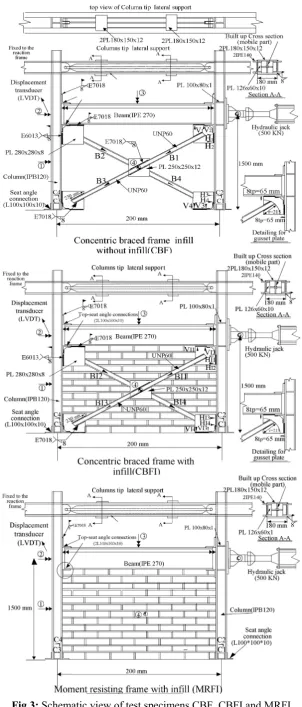
The experimental program was conducted at IIEES (International Institute of Earthquake
Engineering and Seismology, Tehran, Iran). Fig. 3 shows the schematic view of the test
specimens. Out-of-plane buckling supports for the column tips consisted of two parallel
IPE140 beams at two sides of the column as shown in Fig. 3. The half scale frame specimens
were 250cm long and 167cm high, and they were fabricated using IPE270 and IPE120 sections
as beam and column elements, respectively. Brace elements were UNP 60 with slenderness
ratios x= KxL/rx=56 and y= KyL/ry=34; and b/t ratio of 5. Infill panels consisted of
219×110×66 mm solid clay bricks (with no voids) placed in a running bond with 22 courses
within the surrounding steel frame. The thickness of the infill panel was 110 mm.
-0.05 -0.04 -0.03 -0.02 -0.01 0 0.01 0.02 0.03 0.04 0.05
0 20 40 60
Number of cycles
S
to
re
y
d
ri
ft
a
n
g
le
(
ra
d
ia
n
)
(b)
(a)
Double angle connections with L section (L100x100x10 mm) were used for
beam-to-column connections. The mid-height and corner gusset plate connections consisted of
250×250×12 mm and 280×280×8 mm plates, respectively. The brace elements and gusset plate
connections in this study were designed to meet the requirements of Special CBFs in
ANSI/AISC 341-05 [1]. By using pushover analysis, the connection design force was
calculated based on the maximum force that can be transferred to the connections. However,
there is no specific detailing for mid-height X brace connections in the AISC design codes.
Brace-to-gusset plate offset is one the important design parameters in CBFs that is defined as
the distance from the end of the brace to the gusset plate yield line (perpendicular to the main
axis of the brace). In this study, the gusset plate connections were designed to provide a good
balance between the potential braces failure and gusset plate weld line fracture (balanced
design). To achieve this, the gusset plates were designed using an elliptical offset of 8 times the
plate thickness (8tp) based on the studies of Yoo et al. [10, 11] (see Fig. 3). Their studies
showed that the elliptical clearance leads to a smaller gusset plate size while keeping
performance equal to or better than that achieved with the 2tp linear clearance defined by
AISC-seismic provisions [1].
Steel columns were braced at both ends in the out of plane directions but they were free
to rotate in the plane of the frame. A rigid element was pinned to the steel columns to simulate
the rigidity that is normally provided by a ceiling system (section A-A in Fig. 3). All
specimens were whitewashed with a fine layer of plaster to help with the visual monitoring of
the tests as shown in Fig.2 (a). To improve the bond strength at the brick-mortar interface,
bricks were pre-soaked to decrease the water absorption from the mortar joints [30]. All brick
panels had full bed and head joints. The compressive strength of the masonry brick was 12.6
MPa based on the average of five brick samples. A full mortar joint was placed between the
masonry panel and the steel frame to provide direct contact with the boundary frame.
To evaluate the compressive strength of the masonry infill, fifteen 3-course masonry
prisms (couplet specimens) were tested based on ASTM C-1314 [31]. The average prism
compressive strength was 7.53 MPa that is less than the average compressive strength of the
bricks and mortar. This is attributed to the premature failure mechanism of masonry prisms in
which vertical splitting of the bricks occurred prior to the crushing of the mortar. The lateral
biaxial tension in the brick elements in this case reduces their crushing strength and increases
the tendency for vertical splitting [32, 33].
Gusset plates and top-seat angle connections were welded with a continuous fillet weld
line using an E7018 welding electrode. E7018 welding electrode can produce a weld that has a
specified Charpy V notch impact toughness of 70 J at −30 C [34]. The material properties of
the steel elements and weld metal are summarized in Table 1.
Table1: Section and material properties
Section Fy(MPa) FU(MPa)
u y
F F
Elongation
Beam web IPE 270 325 458 0.71 26 Beam flange IPE 270 348 485 0.72 23 Column web IPB 120 318 445 0.71 26
Column flanges IPB 120 340 473 0.72 24
Brace section UNP 60 333 462 0.72 26
Welds (7018,
φ
4,mm electrode ) 540 627 0.86 16All of the test specimens were equipped with two horizontal displacement transducers
(LVDT) installed on the columns at the mid-height and at the beam height levels, and one
vertical displacement transducer at the mid-span of the beam (No. 1 to 3 in Fig. 3). Another
LVDT displacement transducer was installed on the geometric centre of the infill panel
(perpendicular to the frame plane) to measure the out of plane deflection of masonry infill (No.
4 in Fig. 3). This LVDT was mainly used to control the excessive out-of-plane displacement of
the infill panel to prevent damage to the lab equipment. To study the buckling behaviour of
braces, however, the maximum out-of-plane displacement was measured at the end of each
experimental test. Four bi-axial strain gauges were installed on the steel column webs, in the
proximity of the base connections, designated as C1 to C4 in Fig. 3. Bi-axial strain gauges
allow strain measurements in two orthogonal directions, which can be used to calculate the
principle stresses in the connection areas. Four uni-axial strain gauges were installed on the
brace elements of the test specimens CBF and CBFI to measure strains parallel to the main
axes of the braces (B1 to B4 in Fig. 3). The strain gauges on brace elements can measure both
axial and out-of-plane bending strains. However, the strains measured before buckling were
mainly axial strains. Four horizontal (H1 to H4) and four vertical (V1 to V4) uniaxial strain
gauges were installed on the vertical and horizontal re-entrant corners of the gusset plate
connections (close to the fillet weld lines) as shown in Fig. 3. The main aim of using strain
gauges on gusset plate connections was to measure the strain values close to the critical points
on the fillet weld lines, and to study the effects of infill panel on the strain distribution in the
connections.
4- ANALYTICAL MODELLING
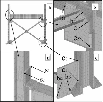
The nonlinear cyclic behaviour of the test specimens is studied using detailed FE models
that are validated with the experimental results. Elastic and inelastic analyses were performed
using ANSYS [35]. For example, the FE model of the test specimen CBF is shown in Fig. 4.
Steel elements and fillet welds were modelled using a 3D solid element (SOLID45). The
material properties used in the analyses were based on the measured stress–strain relationships
obtained from the experimental programme (coupon tests). Similar to the experimental tests,
the cyclic loading protocol shown in Fig 2 (b) was used for analytical studies.
Seat angle connections in the FE models were connected to the beam and column flange
by using contact elements (CONTA174). Large displacement element formulations (see the
ANSYS software manual [35] for more information) were used to simulate buckling of the
brace elements and the local deformation of top-seat angle connections. Nonlinear buckling
behaviour was included in the analysis by taking into account the initial imperfections
consistent with the first buckling mode shape of the braces. The location of the initial
imperfection was obtained from the buckling behaviour observed in the experiments. The small
initial imperfection value was considered to be 0.000001 of the measured buckling
displacement. Contact pair elements (CONTA174-TARGE170) were used to model the
interaction between steel and adjacent brick elements. To calculate the frictional forces
between masonry bricks and steel surfaces, Coulomb’s coefficient (
µ
) was considered to be0.45 as suggested by Shaikh [36]. The Coulomb’s coefficient (
µ
) is the ratio of the friction [image:13.595.124.475.298.643.2]force between two bodies to the force pressing them together.
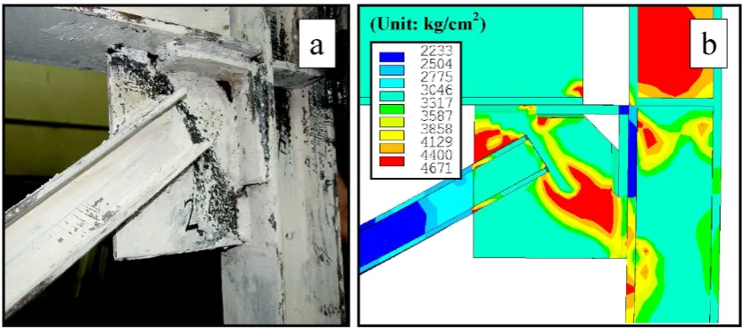
Fig. 4: (a) FE model of test specimen CBF; (b) Critical points on top gusset plate fillet welds; (c) Critical points of bottom gusset plate fillet welds; (d) Critical points on top angle connection weld line.
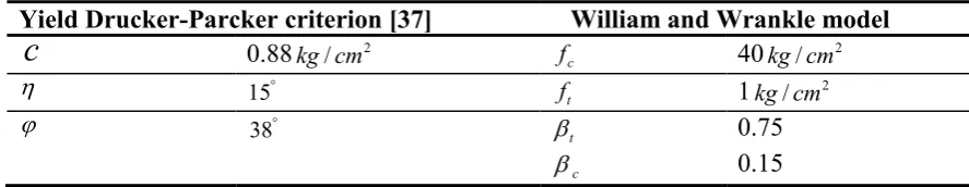
Mortar and masonry units were modelled with the 3D smeared crack element SOLID65
(concrete solid element). The material properties of masonry infill were obtained from a test
programme performed parallel with these experiments using the same masonry infill material
and construction conditions [37-38]. Masonry elements assumed to have a non-linear elastic
behaviour with Young modulus (E) and Poisson's ratio (
υ
) equal to 2500MPaand 0.25,respectively. To represent the non-linear behaviour of masonry material, the Drucker–Prager
yield criterion (with no strengthening hardening effect) is employed in the FE models. This
pressure-dependent yield model can take into account materials with different tensile and
compressive yield strengths, and therefore, is suitable for the modelling of masonry infill
elements [35, 37]. The cohesion factor
c
, angle of internal frictionϕ
, and dilatancy angleη
of masonry material are given in Table 2. Both cracking and crushing failure modes ofmasonry infill were taken into account by using William and Warnke constitutive model [38]
through a smeared model. The parameters corresponding to this failure criterion are calculated
based on the average prism compressive strength of the masonry infill and are given in Table 2.
In this table, ft and fc are uni-axial tensile and compressive strength of masonry material,
respectively. The shear transfer coefficientβ is introduced (depending on the crack status:
open
β
tor re-closedβc) to represent shear strength reduction across the crack face. It shouldbe mentioned that the behaviour of masonry material can be considered to be similar to
concrete, as they are both strong in compression and weak in tension. Therefore, the masonry
material can be adequately modelled using the concrete solid element (SOLID65) with Willam
and Warnke failure surface [39].
The von-Mises stress (or equivalent plastic stress) can be used to predict yielding of
ductile materials (such as steel) under different loading conditions [11]:
5 . 0 2 2 2 2
2 2
)]) (
6 ) (
) (
) [(
2 1
( x y y z z x xy yz zx
eff
σ
σ
σ
σ
σ
σ
σ
σ
σ
σ
= − + − + − + + +(1)
where σx, σy,σz,σxy,σyzand σzxare different stress components. The von-Mises stress
(σeff ) distribution in the analytical models is used to predict the location, initiation and
spreading of yield lines and areas of stress concentration in steel elements and fillet welds.
Table 2. Yield criterion and constitutive model parameters
Yield Drucker-Parcker criterion [37] William and Wrankle model
c
0.88 2/cm
kg fc 40
2
/cm kg
η °
15 ft 1
2
/cm kg
ϕ °
38 βt 0.75
c
β 0.15
5- EXPERIMENTAL INVESTIGATION
The results of the cyclic tests on CBF, CBFI and MRFI test specimens are explained and
discussed in this section.
5-1-Special concentrically braced frame without masonry infill (CBF)
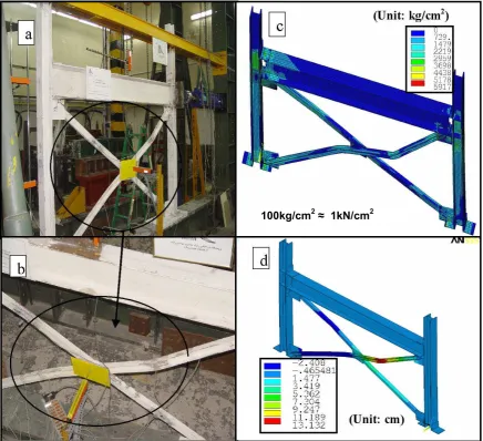
Fig. 5 (a) shows the test specimen CBF under cyclic loading tests. The first yielding in
the CBF specimen was observed in the bracing elements at the 14th cycle of the applied loading
(storey drift angle of 0.008 rad). Subsequently, diagonal yield lines were appeared on the
gusset plates at the 16th cycle (storey drift angle of 0.008 rad). The onset of brace yielding was
axial yielding initiated between the mid-height and corner gusset plate connections.
Out-of-plane buckling of braces occurred at storey drift angle of 0.012 rad that was followed by a
significant flexural yielding in the brace elements as shown in Figs. 5 (b) and (c). The local
buckling and yielding of the brace elements can be recognized by flaking off the white washed
area on the brace elements [9-10]. Fig. 5 (d) shows the out-of-plane displacement of brace
elements in the analytical model that compare well with the white washed areas as shown in
Fig. 5 (b). This indicates that the analytical model could predict the buckling mode of the
braces with a good accuracy.
By increasing the imposed displacement, the CBF specimen exhibited noticeable
inelastic behaviour. The brace elements exhibited about 13.5 cm out-of-plane buckling at the
48th cycle (storey drift angle of 0.025 rad). At this stage, the experimental test was terminated
to prevent damage to laboratory equipment (such as LVDT transducer). The maximum
plane displacement in the analytical model at the same load level was 13.1 cm that is in good
agreement with the experimental observations.
Fig 5: (a, b) Front view of test specimen CBF showing the out-of-plane buckling of the brace elements; (c) Von-Mises stress distribution in the analytical model of CBF test specimen; (d) Out-of-plane
displacement of braces in the analytical model
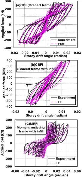
Fig. 6 (a) presents the cyclic hysteretic behaviour of the test specimen CBF. The results
show stiffness degradation and pinching during the cyclic tests that was mainly due to the
buckling of the brace elements. Strength degradation at each storey drift angle was calculated
based on the lateral strength at the end of load cycles to the initial strength. The peak and the
ultimate load strength of the test specimen CBF were 282 kN and 258 kN, respectively. The
strength degradation of CBF specimen was almost 9% at the storey drift angle of 0.025 rad
where the test was terminated.
100kg/cm2≈ 1kN/cm2
[image:16.595.80.517.125.523.2](a)CBF(Braced frame) -300 -200 -100 0 100 200 300
-0.03 -0.02 -0.01 0 0.01 0.02 0.03 Storey drift angle (radian)
A p p li e d f o rc e ( k N ) Experiment FEM (b)CBFI
(Braced frame with infill)
-400 -300 -200 -100 0 100 200 300 400
-0.02 -0.01 0 0.01 0.02
Storey drift angle (radian)
[image:17.595.159.433.64.654.2]A p p li e d f o rc e ( K N ) Experiment FE
Fig. 6: Plot of analytical and experimental load-displacement response of (a): Braced frame without infill; (b): Braced frame with infill; (c): Moment resisting frame with infill
Fig. 7(a) shows the flaking off the whitewashed area on the gusset plate connections at
the end of the experimental test. The measured strains on bracing members (B1 to B4) and the
coincident with the yielding of the gusset plates (see Figs. 5 and 7). This confirms the
efficiency of the design procedure suggested by Yoo et al. [10, 11] to have a controlled
yielding mechanism in brace elements and gusset plate connections.
Fig 7: (a) Flaking off the whitewashed area on the gusset plate connection of test specimen CBF; (b) Von-Mises stress (equivalent plastic stress) distribution of the gusset plate connection
5-2-Special concentrically braced frame with masonry infill (CBFI)
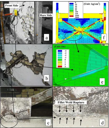
Fig. 8 (a) shows the front view of the test specimen CBFI. Unlike the CBF, steel yielding
in this specimen occurred first in the columns, and followed by the yielding of the brace
elements and gusset plates at the 18th cycle of the loading (storey drift angle of 0.01 rad). This
behaviour can be mainly attributed to the interaction between the masonry infill and the
surrounding frame, which increased the strain demands in columns and gusset plate
connections. At this stage some inclined cracks were appeared at the top and bottom corners of
the masonry infill panel close to the gusset plates, and a large part of the whitewashed infill
flaked off in the vicinity of the brace elements and mid-connection gusset plate (see Figs. 8 (a)
and (b)). Subsequently, the brace elements exhibited local buckling at 22nd cycle of the loading
(storey drift angle of 0.012), which resulted in an out-of-plane separation between the masonry
infill and the braces as shown in Figs 8 (a) and (b). The local buckling of the brace elements
occurred between the mid-height and end gusset plate connections, and was mainly observed in
the flange. At this stage, vertical and stair-stepped cracks were developed in the infill panel
[image:18.595.89.510.153.338.2]from the mid-connection gusset plate towards the corner gusset plate connections. Some
inclined stair-stepped cracks were also appeared along the brace elements and eventually
penetrated into the rear side of the infill panel as shown in Fig. 8 (a). At storey drift angle of
0.015 rad, horizontal sliding cracks developed along the bed joints of the masonry infill panel.
This was followed by yielding and buckling of the braces (see Figs. 8 (a) and (b)) and fracture
of the fillet welds at horizontal re-entrant corner of the gusset plate connections (see Figs. 8 (c)
and (d)). This behaviour almost coincided with the fracture of the welded top-seat angle
beam-column connection, and the test was terminated at this point. The brace elements exhibited
about 5.2cm out-of-plane buckling at the end of the experiment, which is in good agreement
with 4cm out-of-plane displacement in the analytical model.
The hysteretic behaviour of the test specimen CBFI is shown in Fig. 6 (b). The peak load
and the ultimate load capacity of the test specimen CBFI were 398 kN and 405 kN,
respectively. Based on the results presented in Fig. 6 (b), the strength degradation for this
specimen was calculated 22% at the storey drift angle of 0.015 rad where the test was
terminated. The experimental observations showed that the masonry infill could not prevent
out of plane buckling of the brace elements. This is in agreement with the structural damage
observed in the Bam earthquake [40].
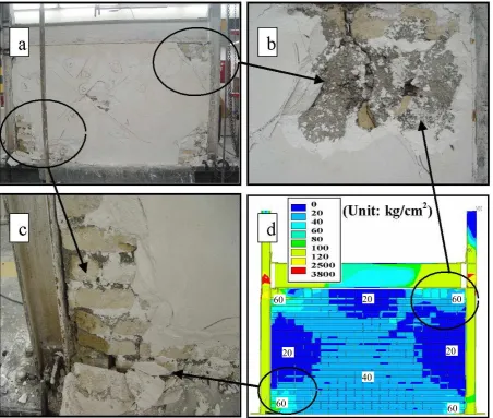
5-3- Moment resisting frame with masonry infill (MRFI)
The test specimen MRFI exhibited elastic behaviour in the first eight cycles of the
applied loading. At storey drift angle of 0.008 rad, two off-diagonal hairline cracks were
formed in the infill panel at approximately 45° in the top compression corners, which means
that diagonal compression strut mechanism was fully developed. These cracks then joined the
horizontal sliding cracks near the mid-height of the masonry infill panel. The first crushing
appeared in the corners of masonry panel at 49th cycle of the loading corresponding to storey
drift angle of 0.025 rad. This was followed by a separation between masonry infill and the
displacement increased. The strain measurements (C1 to C4 in Fig. 3) showed that yielding at
column base started at storey drift angle of 0.017 rad. However, permanent deformations just
became visible at the story drift angle of 0.035 rad. Fig 9 shows the separation of plaster from
the masonry infill in the test specimen MRFI and the failure pattern in the masonry panel.
Fig 8: (a, b) Front view of the test specimen CBFI showing the local buckling of the brace elements and separation between masonry infill and braces; (c, d) Fracture of the fillet weld at re-entrant corner of the
gusset plate (rear side); (e) Out-of-plane displacement of braces ;(f) Von-Mises stress distribution
Rare Side Front Side
Fillet Weld Rupture
[image:20.595.69.526.173.713.2]Fig 9: (a, b, c) Crushing of the masonry infill at the corners of test specimen MRFI and separation between plaster and masonry infill; (d) Von-Mises stress distribution in the analytical model
The peak lateral load applied to the MRFI specimen was 272 kN at 14th load cycle (drift
angle of 0.018 rad). At this point, crushing of infill initiated at the top left and top right corners
of the panel and propagated along the beam and column elements. Subsequently, successive
horizontal and vertical cracks appeared all over the infill panel. Most of the cracks were
through the bed and head joints, while few cracks were through bricks. These brick cracks
formed two new off diagonal struts after occurrence of corner crushing in the masonry infill
(see Fig 9 (a)). The infill panel exhibited further cracking at the subsequent displacement
amplitudes. Severe corner crushing occurred at storey drift angle of 0.043 rad, and afterwards
the load gradually dropped to 139 kN. The test was stopped at this point due to the fracture of
the weld lines of top angle beam-column connections as shown in Figs 10 (a) and (b).
60
60 60
60 40
20
20 20
[image:21.595.71.524.67.450.2]In general, the crack pattern observed in the MRFI test specimen shows that the stressed
part of the infill (i.e. equivalent diagonal strut) has a non-prismatic cross section with a large
width in the centre of the infill panel. The cyclic hysteretic behaviour of the test specimens
MRFI is shown in Fig 6 (c). The results indicate that the strength degradation of this specimen
[image:22.595.89.510.201.596.2]was around 29% at the storey drift angle of 0.043 rad.
Fig 10: (a) Deformed shape of top-seat angle connection for test specimen MRFI; (b) Flaking off the white washed area of the top-seat angle connection and fracture of the welded top angle; (c) and (d)
Von-Mises stress distribution of top seat-angle connection
5-4- Discussion of Test Results
As it was discussed in the previous sections, fracture of the fillet welds at re-entrant
corners of gusset plate connections (in CBFI specimen) and failure of the top-seat angle
connections (in CBFI and MRFI specimens) were two dominant failure modes in the test
Fracture of the weld line
specimens with masonry infill. These undesirable failure modes could be due to the interaction
between masonry infill and the frame that resulted in an increase in the load transferred
through the gusset plate and top-seat angle connections.
Fig. 11 shows the measured strain demands of the brace elements, and horizontal and
vertical re-entrant corners of gusset plate connections of the test specimens CBF and CBFI.
The results shown in Fig 11 (a) indicate that the maximum measured horizontal strains at
vertical re-entrant corners of the gusset plate connections are around 35% higher in the CBF
specimen compared to the CBFI, mainly due to its higher lateral deformation capacity as
mentioned before. However, for the same storey drift angle, the maximum measured horizontal
strain in the CBFI specimen is, on average, 30% greater than the corresponding value in the
test specimen CBF. It is shown in Fig. 11 (b) that, for the same storey drift angle, the presence
of masonry infill significantly increased the vertical strain at the gusset plates connections. The
maximum vertical uniaxial strain at horizontal re-entrant corners of gusset plates reached 3150
and 4920 microstrain in the test specimens CBF and CBFI, respectively. This indicates that, at
the failure point, the composite action of the frame-infill system can considerably increase the
strain demands in the vicinity of horizontal re-entrant corners of gusset plate connections. This
can explain the reason for the undesirable failure mode (i.e. failure of gusset plate connections)
in the specimens with masonry infill.
Fig. 11 (c) compares the measured strain at brace elements (B1 to B4 in Fig. 3). It is
shown that the maximum strain measured in the brace elements of CBF and CBFI specimens
were 12324 and 4260 microstrain, respectively. This indicates that, at the failure point, the
brace elements of the CBF specimen (without masonry infill) experienced almost 3 times more
accumulated nonlinear strain (axial and flexural) compared to the CFI specimen (with masonry
infill). This difference can be attributed to the higher out-of-plane displacements in the CBF
specimen at the failure point. It is shown in Fig. 11 (c) that, for the same storey drift angle, the
measured strain in the braces of the CBFI specimen was always 50% to 70% less than the
corresponding value in the test specimen CBF. This conclusion is valid even for very small
storey drift angles, where no out-of-plane deflection was observed. The results, in general,
show that the contribution of the brace elements to the lateral strength and stiffness of the
concentrically braced frame was significantly reduced after using masonry infill panel.
Fig. 12 (a) shows the upward beam mid-span deflection of CBF, CBFI and MRFI test
specimens (LVDT No. 3 in Fig. 3) at different storey drift angles. These measurements are
used to study the interaction between masonry infill and the surrounding frame. It is shown that
the test specimen CBFI experienced maximum upward deflection at the mid-span of the steel
beam compared to the other specimens. This behaviour demonstrates the effects of masonry
infill on the lateral load distribution pattern of the CBF, which results in additional shear loads
on the connections. Fig. 12 (b) compares the energy dissipation in different test specimens
versus number of load cycles. The results indicate that, for similar load cycle (or storey drift
angle), CBFI and MRFI test specimens absorbed the maximum and the minimum energy,
respectively, compared to other test specimens.
The secant stiffness of different test specimens are calculated by dividing the lateral load
value at each storey drift angel by the corresponding lateral frame displacement as given in
Table 3. The results indicate that CBFI and MRFI specimens had the largest and the smallest
lateral stiffness at all storey drift angles, respectively. Table 3 shows that the difference
between lateral stiffness of the test specimens CBFI and CBF (i.e. the influence of masonry
wall) was significantly increased after buckling of the braces. The results shown in Fig. 6
indicate that the maximum lateral load capacity of the CBFI specimen was also 41% more than
the similar frame without masonry infill (CBF specimen). However, the deformation capacity
of the CBFI was considerably less (almost 40% less) than the CBF due to the premature failure
in the connections. This unfavourable behaviour is due to the fracture in gusset-plate and
top-seat angle connection welds, and it is especially important when frame exhibits large lateral
deflections under strong earthquakes. Although the MRFI specimen experienced the maximum
lateral deflection at the failure point, it exhibited the lowest energy dissipation capacity
compared to the other specimens. It is in agreement with the results presented in Fig. 12 (b).
-3000 -2000 -1000 0 1000 2000 3000 4000
-0.025 -0.015 -0.005 0.005 0.015 0.025
M e a s u re d m ic ro s tr a in
Storey drift angle (radian)
Horizontal strain at vertical re-entrant corners
H1 H2 H3 H4 HI1 HI2 HI3 HI4 Yeild strain Yeild strain Tension compression
a
-3000 -1500 0 1500 3000 4500 6000-0.025 -0.015 -0.005 0.005 0.015 0.025
M e a s u re d m ic ro s tr a in s
Storey drift angle (radian)
Vertical strain at horizontal re-entrant corners
V1 V2 V3 V4 VI1 VI2 VI3 VI4 Yeild strain Yeild strain Tension Compression
b
-8000 -4000 0 4000 8000 12000-0.025 -0.015 -0.005 0.005 0.015 0.025
M e a s u re d m ic ro s tr a in
Storey drift angle (radian)
[image:25.595.165.435.123.737.2]Strain at braces elements B1 B2 B3 B3 BI1 BI2 BI3 BI4
C
Yeild strain Yeild strain Tension CompressionFig. 11: Measured strain at: (a) Horizontal re-entrant corners of gusset plate connections; (b) Vertical re-entrant corners of gusset plate connections; (c) Brace elements (test specimens CBF and CBFI)
Fig. 12: (a) Measured upward mid-span deflection of the top beam; (b) Energy dissipation of different test specimens
Table 3: Lateral stiffness of CBF, CBFI and MRFI test specimens at different load
Cycle
CBF CBFI MRFI
Lateral force (kN) Lateral Stiffness (kN/m) Lateral force (kN) Lateral Stiffness (kN/m) Lateral force (kN) Lateral Stiffness (kN/m)
6th 30 26270 35 29208 28 22122
12th 64 23333 70 26309 45 18108
18th 138 18550 173 22401 130 12414
22nd 190 13734 230 18113 223 8920
24th 242 11225 376 16635 195 7217
26th 250 9800 --- --- 180 6123
28th 267 7813 --- --- 170 4925
30th 271 5912 --- --- 160 3918
32nd --- --- --- --- 136 2613
34nd -- --- ---- ---- 118 1535
The response reduction factor (or force modification factor) R reflects the capacity of a
structure to dissipate energy through inelastic behaviour. The R factor includes the effects of
over-strength, ductility and redundancy of the structure, and can be calculated as the ratio of
elastic strength demand to the design strength [16]. In this study, the back bone curve (lateral
load-displacement envelope) was obtained for each test specimen based on FEMA-356 [16],
and used to calculate elastic strength demand, design strength and yield displacement. The
response reduction factor, R, for CBF, CBFI and MRFI test specimens was 6.4, 3.6 and 4.4,
respectively. A higher R factor is usually indicative of a structural system that can 0 2 4 6 8 10 12 14 16 18
0 0.015 0.03 0.045 0.06
B e a m 's m id -s p a n d e fl e c ti o n ( m m )
Storey drift angle (radian)
(LVDT No. 3) CBF
CBFI MRFI
a
0 20 40 60 80 100 1200 20 40 60
A b s o rb e d e n e rg y ( J o u le s )x 1 0 3
Number of cycles
CBF CBFI MRFI
b
accommodate more inelastic deformation and ductility. It implies that the CBFI specimen is
expected to exhibit lower ductility compared to the MRFI specimen. The results indicate that
the presence of masonry infill can significantly reduce (up to 40%) the response reduction
factor (and ductility) of CBFs, and can lead to a non-ductile behaviour if it is not taken into
account in the design process. This is further studied in the next section by using analytical
models of the test specimens.
6- ANALYTICAL STUDY
The FE models defined in section 4 are used to simulate the cyclic inelastic response of
the test specimens at both global level (e.g., lateral displacement of the frame) and local level
(e.g., strain demands of gusset plate and top-seat angle connections). The hysteretic behaviours
obtained from analytical models and experimental tests are compared in Fig. 6. The results
show a good agreement between the measured and simulated responses for all test specimens.
It is shown that the FE models accurately predicted the inelastic lateral drift of the tested
frames at different load levels (with less than 6% error).
The out-of-plane buckling of brace elements observed in the experimental tests (Figs.
5(b) and 8(b)) in general compare well with the analytical results shown in Figs. 5(d) and 8(e).
Maximum out-of-plane displacement of braces in the test specimens CBF and CBFI were
measured to be 13.5 and 5.2 cm, respectively. For the same load levels, the corresponding
analytical results were 13.1 and 4 cm, which can demonstrate the capability of the analytical
models to simulate out-of-plane buckling behaviour of braces.
It is shown in Fig. 10 that the von-Mises stress distribution of top angle connection
compares well with flaking off the white washed area and fracture of the fillet welds. Similarly,
Figs. 8 and 9 show that the distribution of von-Mises stress in the infill panel in the analytical
models was comparable to the crack pattern and crushing zones observed in CBFI and MRFI
specimens. For instance, corner crushing of the masonry infill observed in the test specimen
MRFI (Figs. 9 (b) and (c)) is in good agreement with the higher von-Misses stress in the same
area in the analytical model (Fig. 9 (d)).
It is shown in Fig. 7 that the distribution of von-Mises stress in the gusset plate
connections compares fairly well with the flaking off the whitewashed area and the observed
yield lines. The difference between the results may be due to the approximation associated with
the material yield criterion used in the analytical models (i.e. von-Mises yield criterion), which
cannot always capture the real behaviour of steel martial.
7- ASSESSING THE RUPTURE POTENTIAL OF CONNECTIONS
The crack propagation in steel elements was not modelled explicitly in this study.
However, in parallel with the test observations, the rupture index (RI) was used to predict and
monitor crack initiation in the connections of the test specimens [41-43]:
− = eff m y pl eqv RI σ σ ε ε . 5 . 1 exp (2)
where pl eqv
ε , εy,
σ
m and σeff are the equivalent plastic strain, yield strain, hydrostaticstress, and von-Mises stress, respectively. The pl eqv
ε can be calculated from the following
equation:
(
) (
) (
)
(
)
21 2 2 2 / 2 2 2 3 2 ) 1 ( 2 1 − + − + − + + + + = pl zx pl yz pl xy pl z pl z pl z pl y pl y pl x pl
eqv ε ε ε ε ε ε γ γ γ
υ
ε (3)
where
ε
ypl,ε
xpl,γ
xypl etc. are the appropriate components of the plastic strain andυ
/is theeffective Poisson's ratio. Since the loading protocol used for experimental and analytical
studies was cyclic, the gusset plates were imposed by both tension and compression. In this
study, the larger value of RI in compression and tension was considered as the rupture index
for each load cycle (or storey drift angle). In general, locations with higher values of RI have a
The ratio of the hydrostatic stress to the von-Mises stress (i.e.
eff m σ
σ / ), which appears
in the denominator of Eq. (2), is called the triaxiality ratio (TR). It has been reported by
El-Tawil et al. [43] that TR values less than −1.5 can cause brittle fracture, whereas values
between −0.75 and −1.5 can cause large reductions in the rupture strain of metals.
The fracture of gusset plate welds is an undesirable failure mode for CBFs, which can
decrease their seismic performance as a lateral resisting system. To study the influence of
masonry infill on the rupture potential of CBFs, the rupture index (RI), triaxiality ratio (TR)
and equivalent plastic strain ( pl eqv
ε ) were calculated at the critical points of the test specimens.
These critical points (see Fig. 4) were identified on the gusset plate and top angle connection
weld lines of CBF and CBFI specimens based on experimental test observations and high
stress demand regions in FE models. b1, b2, b3 and b4 in Fig. 4 are critical points on the
horizontal re-entrant corner of gusset plate connections of the CBF specimen. Similar points on
the CBFI specimen are named b1i, b2i, b3i and b4i. Similarly, c1, c2, c3, c4 and c1i, c2i, c3i, c4i are
critical points on the gusset plate connection weld lines of the CBF and CBFI specimens,
respectively. It should be emphasised that the locations of the strain gauges in the test
specimens were on the gusset plates close to the fillet welds (shown in Fig. 3), whereas the
locations of the critical points in the analytical models were on the fillet weld lines .
The equivalent plastic strain ( pl eqv
ε ), triaxiality ratio (TR), and rupture index (RI) of the
critical points are presented in Fig. 13 as a function of storey-drift angle. Figs 13 (a) and (d)
show that the equivalent plastic strain of horizontal and vertical re-entrant corners of gusset
plate connections significantly increased in the CBFI specimen. This increment was
particularly noticeable for horizontal re-entrant corners, and can explain the change in the
failure mode from excessive out of plane buckling of braces in the CBF specimen (without
masonry infill) to fracture of the fillet welds at horizontal re-entrant corner of the gusset plate
connections in the CBFI specimen (with masonry infill) as discussed in previous sections.
Comparison between Figs. 13 (a) and (d) indicates that horizontal re-entrant corner of gusset
plate connections of both CBF and CBFI specimens were, in general, under higher plastic
strain demands compared with the vertical re-entrant corners. The equivalent plastic strain
( pl eqv
ε ) at b3 and b4 was 0.008 and 0.015, respectively, at the failure point of the CFB test
specimen (storey drift angle of 0.025 rad). Corresponding points at CBFI specimen (b3i and b4i)
exhibited equivalent plastic strain ( pl eqv
ε ) of 0.024 and 0.033, respectively, at storey drift angle
of 0.015 rad where the experimental test was terminated. This implies that the CBFI specimen
(with masonry infill) experienced 40% less lateral displacement, but almost two times more
equivalent plastic strain in the horizontal re-entrant corner of gusset plate connections. This is
in agreement with the experimental results discussed in previous sections.
Figs. 13 (b) and (e) compare the triaxiality ratio (TR) index of the critical points of the
gusset plate connections in CBF and CBFI specimens. It is shown that the TR indices of both
specimens were initially decreased up to storey drift angles around 0.004. This indicates a
faster increment in the hydrostatic stress compared to the von-Mises stress before yielding
initiates in the gusset plate connections. The results shown in Figs. 13 (b) and (e) indicate that
the triaxiality ratio (TR) in both horizontal and vertical re-entrant corners of gusset plate
connections were slightly less (i.e. more critical) in the CBF without masonry infill. The TR
index of both CBF and CBFI specimens at failure points lies between −0.75 and −1.5, which
results in a reduction in the rupture strain of the connections [43].
In general, there was a good agreement between the rupture indices calculated from the
FE models and the failure of gusset plate connections observed in the experimental tests. It is
shown in Figs. 13 (f) and (c) that the rupture index (RI) for horizontal and vertical re-entrant
corners of gusset plate connections in the CBFI was considerably higher (up to 5 times) than
the corresponding value in the CBF specimen. This indicates that the interaction between
masonry infill and concentrically braced frame significantly increased the potential for crack
initiation at gusset plate connection weld lines. The maximum rupture index (RI) in the gusset
plate connections of the CBFI specimen was calculated at b3i and b4i locations on horizontal
re-entrant corner of the bottom gusset plate weld line (see Fig. 4). This is in complete agreement
with the damage observed in the experimental tests as shown in Figs. 8(c) and (d).
Overall, the results discussed above show that the interaction of masonry infill and
braced frame results in a considerable increase in the strain demands and the rupture index of
gusset plate connections, which significantly increase the potential for weld fracture and
premature failure of the connections.
0 0.01 0.02 0.03 0.04 0.05 0.06
0 0.01 0.02 0.03 Storey drift angle (radian)
E q u iv a le n t p la s ti c s tr a
in b1 b2 b3 b4
b1i b2i b3i b4i
a d 0 0.005 0.01 0.015 0.02 0.025 0.03
0 0.01 0.02 0.03 Storey drift angle (radian)
E q u iv a le n t p la s ti c s tr a
in c1 c2 c3 c4
c1i c2i c3i c4i
b -2 -1.5 -1 -0.5 0
0 0.01 0.02 0.03
Storey drift angle (radian)
T ra x il it y r a ti o ( T R )
b1 b2 b3 b4
b1i b2i b3i b4i
e -2 -1.5 -1 -0.5 0
0 0.01 0.02 0.03
Storey drift angle (radian)
T ra x ia li ty r a ti o (T R )
c1 c2 c3 c4
c1i c2i c3i c4i
c 0 0.025 0.05 0.075 0.1
0 0.01 0.02 0.03
Storey drift angle (radian)
R u p tu re i n d e x ( R
I) b1 b2 b3 b4
b1i b2i b3i b4i f
0 0.02 0.04 0.06
0 0.01 0.02 0.03
Storey drift angle (radian)
R u p tu re i n d e x (R I)
c1 c2 c3 c4
c1i c2i c3i c4i
Fig. 13: Response indices of the critical points on the horizontal and vertical re-entrant corners of gusset plates.
As it was explained before, the fracture of top angle connection welds was another failure
mode that occurred in CBFI and MRFI specimens (test specimens with masonry infill) at
storey drift angle of 0.015 and 0.043 rad, respectively. To study this failure mode, the Rupture
Index (RI) was calculated for the most critical points on the top-seat angle connection weld
lines (S1 and S2 in Fig. 4 (b)). Fig. 14 compares the maximum value of RI in S1 and S2 locations
for CBF, CBFI and MRFI test specimens versus storey drift angle. It is shown that the CBFI
specimen had the highest potential to experience rupture in the weld line of top angle
connections, which is in complete agreement with the experimental results of this study. Fig.
14 shows that, for similar storey drift angle, the concentrically braced frame with masonry
infill (i.e. CBFI specimen) exhibited up to 8 times higher RI compared to the similar frame
without masonry infill (i.e. CBF specimen). This implies that the presence of masonry infill
can significantly increases the rupture potential of top-seat angle connection weld lines in
special CBFs. As it was discussed in the previous sections, the interaction between masonry
infill and surrounding frame applies an up-ward pressure on the top beam, which increases the
vertical load (shear force) in the top-seat angle connections. This additional shear force can
result in a premature fracture of the connection welds, and can explain the reason this rupture
mode was only observed in the frames with masonry infill (i.e. CBFI and MRFI specimens).
0 0.005 0.01 0.015 0.02
0 0.01 0.02 0.03 0.04 0.05
R
u
p
tu
re
in
d
e
x
(R
I)
Storey drift angle (radian)
MRFI
CBFI
[image:32.595.169.426.553.740.2]CBF
The existence of masonry infill is usually ignored in the design process of CBFs in
practice. However, the results of this study show that the infill panel can considerably increase
the maximum strain demand and the failure potential of gusset-plate and top-seat angle
connection welds. Therefore, ignoring the influence of masonry infill in the design process
may result in a premature failure of the connections and a significant reduction in the
deformation capacity and ductility (or response reduction factor) of the frame, which can
adversely influence the seismic performance of the whole structural system under strong
earthquakes.
8- SUMMARY AND CONCLUSIONS
The effects of masonry infill on the seismic performance of CBFs are experimentally and
analytically investigated. Cyclic lateral load tests were conducted on three half-scale specimens
including a special CBF without masonry infill, a special CBF with masonry infill, and a
moment resisting frame with masonry infill for comparison purposes. Nonlinear cyclic
analyses were performed to study the influence of masonry infill on rupture indices of gusset
plates and top-seat angle connections using detailed FE models validated with experimental
results. The following conclusions can be drawn from the experimental tests and analytical
simulations:
1- Experimental results indicate that the presence of masonry infill increased the lateral
stiffness and strength of the CBF by 33% and 41%, respectively. However, it reduced the
deformation capacity and ductility of the frame by almost 40%.
2- It is shown that the interaction between masonry infill and CBF considerably decreased the
load-carrying contribution of brace elements, while it increased the strain demands of
gusset plate connections by more than 50%.
3- By using masonry infill, the failure mode of the frame changed from excessive out of
plane buckling of braces to the fillet weld fracture in gusset plates and top-seat angle
connections. This is in agreement with the damage observations in the 2003 Bam
earthquake in Iran.
4- The results of the detailed FE models compared well with the experimental results of the
three test specimens. It is shown that the analytical models can predict the non-linear
cyclic behavior of the test specimens at both global and local levels.
5- Analytical simulations showed that, compared to the bare frame, the CBF with masonry
infill exhibited almost two times more equivalent plastic strain ( pl eqv
ε ) and up to 5 times
more rupture index (RI) at the weld lines of gusset-plates and top angle connections. This
implies that ignoring the influence of masonry infill in the design process of special CBFs
may result in a premature brittle failure of the connections and a lower seismic
performance under strong earthquakes.
9- ACKNOWLEDGM ENTS
This research was funded by the Structural Engineering Research Centre at International
Institute of Earthquake Engineering and Seismology (IIEES) (Grant No., 7520). The authors
would like to thank Dr A.S. Sarvghad Moghadam, director of Structural Research Centre at
IIEES, and all laboratory technicians and staff for their valuable help and support.
REFERENCES
[1] ANSI/AISC 341-05. Seismic Provisions for Structural Steel Buildings. Chicago (IL): American
Institute of Steel Construction; 2005.
[2] AISC. Manual of steel construction load and resistance factor design. 3rd ed. Chicago (IL):
American Institute of Steel Construction; 2001.
[3] Johnson S. Improved seismic performance of special concentrically braced frames. Master’s thesis,
Dept. of Civil Engineering, Univ. of Washington, Seattle; 2005.
[4] Thornton WA. On the analysis and design of bracing connections: Proceedings of national steel
construction conference. Chicago (IL): AISC; P. 1–33. Section 26; 1991 .
[5] Pirmoz A, Daryan A, Mazaheri A, Darbandi EH. Behaviour of bolted angle connections subjected to
combined shear force and moment. Journal of Constructional Steel Research 2008; 64:436–446.
[6] Danesh F, Pirmoz A, Daryan A. Effect of shear force on initial stiffness of top and seat angle
connections with double web angles. Journal of Constructional Steel Research 2007; 63(9): 1208–18.
[7] Lehman DE, Roeder CW, Herman D, Johnson S, Kotulka B. Improved seismic performance of
gusset plate connections, ASCE Journal of Structural Engineering 2008; 134(6): 890-901.
[8] Uriz P, Mahin S. Seismic performance of concentrically braced steel frame buildings, in:
Proceedings, 13th world congress on earthquake engineering. Paper ID 1639; 2004.
[9] Roeder C, Lehman D, Yoo JH. Improved design of steel frame connections. International Journal of
Steel Structures 2006; 5(2):141–53.
[10] Yoo, JH, Roeder C, Lehman D. Analytical Performance Simulation of Special Concentrically
Braced Frames simulation and failure analysis of special concentrically braced frame tests, ASCE,
Journal of Structural Engineering 2007; 134(6): 881-889.
[11] Yoo JH , Dawn E Lehman, Charles Roeder W. Influence of connection design parameters on the
seismic performance of braced frames. Journal of Constructional Steel Research 2008; 64: 607–623.
[12] Mander JB, Nair B, Wojthowski K, Ma J. An experimental study on the seismic performance of
brick-infilled steel frames with and without retrofit. Technical report NCEER 93-0001; 1998.
[13] FEMA 306, Evaluation of earthquake damaged concrete and masonry wall buildings. Applied
technology council (ATC-43 Project);1998.
[14] Durrani AJ, Lou YH. Seismic retrofit of flat-slab buildings with masonry infills. NCEER
Workshop on Seismic Response of Masonry Walls, 1-3 to 1-8; 1994.
[15] Moghadam, HA, Dowling PJ. The state of the art in infilled frames. ESEE report No.87-2; 1987.
[16] FEMA 356.Pre-standard for the seismic rehabilitation of buildings, Federal Emergency
Management Agency, Second draft, March 22; 2000.
[17] Decanini LD, Liberatore L, Mollaioli F. Response of bare and infilled RC frames under the effect
of horizontal and vertical seismic excitation. In: 12th European conf on earthquake engineering; 2002.
[18] Mallick DV, Garge RP. Effect of openings on the lateral stiffness of infilled frames. Proc Instn Civ
Engrs 1971; 49:193–209.
![Fig 2: (a) Experimental test setup; (b) Applied cyclic loading [29]](https://thumb-us.123doks.com/thumbv2/123dok_us/7979195.201895/8.595.73.519.296.486/fig-experimental-test-setup-b-applied-cyclic-loading.webp)