80CXJ7
COMMISSION OF THE EUROPEAN COMMUNITIES
physical sciences
.,. .. _, .
Review of technological requirements
COMMISSION OF THE EUROPEAN COMMUNITIES
physical sciences
Review of technological requirements
for high-temperature materials R
&
D
Joint Research Centre
Published by the
COMMISSION OF THE EUROPEAN COMMUNITIES
Directorate-General
'Scientific and Technical Information and Information Management' Bitiment Jean Monnet
LUXEMBOURG
LEGAL NOTICE
Neither the Commission of the European Communities nor any person acting on behalf of the Commission is responsible for the use which might be made of the
following information
Cataloguing data can be found at the end of this volume
PREFACE
The preparation of a "European High-Temperature Materials White Book" was assigned to the Petten Establishment of the Joint Research Centre by decision of the Council of Ministers of the European Community on August 25th, 1975. The objective was the assessment of the requirements of European industry for . advanced high-temperature materials and the R and D in hand in
the member states and elsewhere, in order to provide criteria for the promotion of R and D in this field.
The Petten Establishment has compiled this White Book under the title "Review of the Technological Requirements for High-Temperature Materials R and D" from contributions by experts from the materials producing and using industries and research organizations. In order to make the view on the subject as broad and complete as possible, each section was originally dealt with by a principal author and then commented upon by a number of specialist reviewers with experience of the
subject. Chapters 5 and 6 summarize the conclusions evaluated on the current R and D and future R and D requirements in Europe.
Although the material presented here covers the major purt of the field, some aspects could not be fully, or not satis-factorily, dealt with. In the case of three of the White Book sections an author could not be contracted in time - only short summaries prepared by the editor are therefore included.
Future White Book revisions or supplements will permit
completion, for in line with the advance of high-temperature materials technology i t is intended to publish from time to
time new information and appraisals of the changing research requirements. Emphasizing the value of stimulating feedback, i t would be appreciated if any comments, suggestions and indications of prominent omissions or inaccuracies could be referred to the indicated address for corre3pondence.
Finally the co-operation of all those who provided information und suggestion is gratefully acknowledged. Thanks are due to all persons who have contributed time and effort ~o the
realization of this survey and to writing, reviewing, editing, typing and publishing this report. Without the ready and
Contents
1 IN'XRODUCTION
2 FUNDAMENTAL CHARACTERISTICS
2.1 Resistance to the Environment 2.2 :Mechanical Properties
2.3 Physical Properties
3 HIGH-TEMPERATURE PROCESSES AND APPLICATIONS 3.1 Definition of Scope
3.2 Chemi,cal Technology
3.3 Electric Heating Elements 3.4 Metallurgical· Industry
3.5 Glass and Ceramics Industry 3.6 Gas Turbines
3. 7 High-Temperature Nucle.ar Reactors 3. 8 Fusion Re·actors
3·. 9 Magne.tohydrodynamic Energy Converters
3.10 Production of Hydrogen by Water Decomposition 3.11 Combustion Engines
4 MATERIALS
4.1 Metals and Alloys
4.2 4.3 4.4 4.5
4~1.1 Ferritic Steels 4.1.2 Austenitic Steels 4.1.3 Nickel-Base Alloys 4.1.4 Cobalt~Base Alloys 4.1.5 Refractory Metals 4.1.6 Platinum-Group Metals Ceramics
Cermets Composites Coatings
5 CURRENT HIGH-TEMPERATURE MATERIALS RESEARCH AND DEVELOP~ffiNT
6 FUTURE HIGH-TEMPERATURE MATERIALS RESEARCH AND DEVELOPMENT
P.PPENDICES:
A Nomenclature
B Material pro~erties primarily relevant to the use of metallic materials in heat-transfer systems
C Compositions of iron-, nickel- and cobalt-base alloys D Trade names and designations of iron-, nickel- and
cobalt-base alloys
E Specifications and designations of high-temperature alloys F Major producers of iron-, nickel- and cobalt-base alloys G Major producers of refractory metals, platinum-group metals,
ceramics and composites
H Trade names, designations, compositions and standards of refractory materials
J Major materials users
K Research organisations, advisory bodies, information offices and standards offices
L Bibliography
M Results of a survey on the need for reference materials used at high temperature (higher than 700°C)
x
Supervision:
Editing:
General coordination:
M. Van de Voorde
x W. Betteridge
H. Krockel
Coordination of Sections
B. Bathe
W. Betteridge
J. Bressers M. Cambini V. Guttmann R.A.U. Huddle x
G. Kemeny R. Krefeld E. Lang
S.J. Lloyd
consultants to JRC Petten
Appendix M
2.1., 2.2., 2.3., 3.3.
5., 6., Appendices A-L
3.8., 4.1.5., 4.1.6. 3.9., 4.1.3., 4.1.4. 3. 2., 3. 4.
3.7.
:L10., 4.5. 4. 2., 4. 3. 3. G.
4.1.2., 4.4.
Address fot correspondence:
H. Kr6ckel
Joint. Research Centre Pet ten
The Netherlands
'rel. (02246) 6442 ext. 28S3
Authors
1 M. Van de Voorde 4.1.1 The Editor
2.1 D.P. Whittle 4.1. 2 N.G. Persson
2.2
w.
Betteridge,E.D. Grosser 4.1.3 K.E. Volk2.3
w.
Betteridge 4.1.4 E. Williams3.1 H. Krockel 4.1.5 R. Eck,G.L. Miller
3.2
c.
Edeleanu,B.J. Estruch 4.1.6 J.C. Chasten3.3 J.H. Davidson 4.2 J. Briggs
3.4
w.
Betteridge,J.H. Davidson 4.3 N. Claussen3.5 The Editor 4.4 C.D. Des forges
3.6 D.J. Burr 4.5 R. Ubank
3.7 L.W. Graham,R.A.U. Huddle 5.
w.
Betteridge,C.D. Des forges3.8 J. Bressers 6.
w.
Betteridge3.9 A.M. Anthony Appendices:
3.10 G. Beg hi A Fulmer Research Institute Ltd.
3.0 The Editor B E. D. Grosser
c
- L Fulmer Research Institute Ltd.M B. Bathe
Specialist Reviewers
A.M. Anthony H. Barnert H. Beutler R. Blackstone E. Bullock J.F.G. Conde P. Courvoisier K. Ehrlich P. Esslinger B. L. Eyre R.J.E. Glenny D.J. Godfrey H.E. Gresham E.D. Grosser R. Hancox J. Harrison H. Hausner J. Henderson G. Henrich J. Heslop I. Kirman P. Kofstad
3.3. 3.10. 3.6. 3.9. 4.4. 4.5. 3.10. 3.8. 3.6. 3. 8.
3. 6 . 4. 2 • 3. 6 . 2. I, 2. 3 3. 8 . 3.4 4.2
3.6
3.7
4. I. 3
4. I. 3 .
2.1.,2.2.,2.3
R. Krefeld H. Marchandise M. Mocellin H. Nickel H.G. Orbans R. Pichoir G. Reinacher B.M.U. Scherzer A. I. Smith
A. Von den Steinen P. Strocchi
R.P. Theisen T. Thomander S. Timoney P. Tipping K. E. Volk C.H. White F.E. White D.P. Whittle G. Wirth
W. Van Witzenburg J. Zboril
3.9. 3.6. 4.2. 3. 7. 3.2. 4.5.
4. I. 6. 3.8.
2.1. ,2.2. ,2.3. 4. 1.3. ,4. 1.4. 4. I. 3.
3.6.
4.5.
3.3. 3.6. 4. I. 5.
2.1. ,2.2. ,2.3. 3.3.,3.4. 4. I. 3. 2.2.,2.3.
1. INTRODUCTION
The general standard of living within a society at any given time is dependent upon the sophistication of the available technology. Technical progress is usually measured in terms of increased efficiency or productivity. Processes involving
high temperatures form an important part of modern industrial activity; however, i t may be questioned whether, with further technical progress, the use of high-temperature processes and the trend towards higher temperatures is likely to increase or decrease. It has for example been suggested that
high-temperature processes are inherently wasteful and that, in the long term, more efficient low-temperature alternatives will be developed. This may be true in a few cases but for a large
number of processes, fundamental thermodynamics predicts that an increase in temperature leads to a higher overall efficiency, e.g. in the conversion of thermal energy to mechanical and subsequently to other forms of energy. Other processes which become more efficient as the temperature is increased are those in which the limiting factors involve microstructural or molecular kinetic processes; in such cases higher efficiency corresponds to a shorter reaction time and therefore higher productivity for the installed equipment.
A concise definition of "high temperature" is rather difficult: in considering the efficiency of energy conversion (power
generation, engines for transport, etc.) and materials
processing (chemical plant, glass and metal melting and shaping, etc.) temperatures above 600°C are usually important. High
temperatures referred to in this White Book correspond to this temperature range.
The development of improved engineering materials is a
difficult empirical activity. The acceptance of a material for a given application is in general a compromise between a large number of more or less stringent property requirements and cost
factors. The large variety of high-temperature materials available is a reflection of the conditions encountered. Until the last
century, the requirements of materials to operate at elevated temperatures were not very critical; low stress levels and moderate temperatures were involved and for many centuries these requirements were satisfied by ceramics derived from the firing of clays and other materials. Modern technology, however, makes much more stringent demands: materials are now required to be able to retain their strength and mechanical properties at higher and higher temperatures, and at the same time maintain adequate resistance to the environment in
While wrought and cast iron possessed adequate properties in the early days of steam power when temperatures and stress levels were rather low, i t later became apparent that in order to increase the thermal efficiency of steam-powered electricity-generating stations, materials with increased strength at
elevated temperatures were required. This led to the
development of special types of low-alloy and austenitic steel5, with improved creep strength and high-temperature oxidation
resistance: the properties of these materials were exploited.
The gas turbine had been developed by the early 1930's as a stationary power unit, and existing ferrous materials were then adequate for the critical components, turbine blades
and vanes, since the unit operated at what must now be regarded as a very moderate temperature, and there was insufficient
economic advantage to justify the development of specially improved materials. However, on the application of the gas turbine to the aircraft jet engine, i t soon became apparent that existing ferrous alloys were inadequate, and attention was directed towards nickel-base and cobalt-base alloys. As a starting point, nickel-chromium heater element alloys, which possessed good oxidation resistance to ll00°C but only modest strength, and the cobalt-chromium dental casting alloys which had similar properties, were modified to improve their high-temperature strength capabilities. These studies led to the development of high-strength, precipitation-hardened nickel-base superalloys, and the somewhat lower strength, solid-solution-strengthened and carbide-strengthened cobalt-base superalloys. The nickel-base superalloys, in particular, have been improved over the last 30 years, with the emphasis on ever increasing high-temperature strength, but with a
simultaneous decrease in the high-temperature
corrosion-resistance as a result of a re-adjustmentof alloy composition. Consequently, the need for protecting the higher strength alloys against excessive corrosive attack by the environment gave rise to the use of protective coatin~s.
In other applications including the chemical, metallurgical and petrochemical industries, it is easier to achieve
a balance between high-temperature corrosion resistance and strength since strength requirements appear to be more
moderate. Since the latter industries require materials in considerable quantities, the material cost factor is an
important element in the selection criteria.
The refractory metals, including tungsten, molybdenum, etc. all possess attractive high-temperature strength, but are handicapped by their very poor oxidation resistance. Attempts to provide adequate protective coatings have been successful in a few cases but the high cost has generally confined their use to spacecraft applications. Chromium-base alloys
A further class of high-temperature materials in which current interest runs very high are ceramics. Ceramics have for a
long time been used as heat-insulating materials; however the development of stronger thermal-shock resistant carbides, nitrides and oxynitrides enables us to consider their use for highly-stressed high temperature components. Their resistance to oxidation is excellent, but their inherent brittleness and lack of reproducible mechanical properties remain the major obstacles, making i t a very challenging problem to utilize their high strength potential.
It is clear then, that the field of high-temperature materials embraces a wide range of metals, alloys and ceramics. Different combinations of corrosion resistance and strength are required in applications ranging from metallurgical, chemical and glass-producing industries, through stationary power generatio~, to
transport by land, sea and air. Many questions remain un-answered and there is considerable scope for creative and
inventive research to support and advance technological 9rogress in many industries. Gas turbines are an example of a principle which had to wait for the development of suitable materials
before i t could become a viable technolgy. The commercialisation of some other technologies such as magneto-hydrodynamics,
(M.H.D.), nuclear fusion, nuclear process heat, etc. are all similarly dependentupon the development of improved materials.
The purpose of this White Book is to review the field of high-temperature materials and their applications so as to
indicate the essential requirements, the state of the technology at the present time, and to identify future trends and areas for development. The report first covers the important
fundamental properties which define the current and likely future performance limits of high-temperature materials. The application areas are then briefly reviewed, followed by a description of materials by categories including alloys, ceramics, composites and coatings. Finally a review of world-wide current research activities enables recommendations
2. FUNDAMENTAL CHARACTERISTICS
Modern high-temperature technology has at its disposal a wide range of materials, and their selection for a particular
application depends on a variety of factors. Where metallic materials are involved mechanical, physical and chemical properties must be considered and while a metal or alloy may be selected largely on the basis of high-temperature strength, there is hardly an application in which the effect of the
interaction of the metal with its environment can be ignored. A very wide range of properties may be relevant when materials are assessed, and a comprehensive list of these is given in Appendix Table B. However for any other material a much more restricted amount of data is usually available. In the follow-ing sections an indication is given of those characteristics which are of major significance in high-temperature technology.
2.1 RESISTANCE TO THE ENVIRONMENT
In this brief review the thermodynamic and kinetic factors involved in high-temperature oxidation and corrosion processes are summarised. Oxidation refers to attack by entirely gaseous components including not only oxygen but also nitrogen,
sulphur, carbon, chlorine, etc. The term "corrosion" usually implies the presence of a liquid medium and a predominantly electrochemical mechanism of reaction; but, in high-temperature technology the term has come to be more loosely applied. "Hot corrosion" is a specific process which certainly appears to involve the presence of a liquid salt layer, but i t is
debatable whether i t acts as an electrolyte in a process analogous to that in low-temperature corrosion.
2.1.1 Thermodynamics
The thermodynamics of reactions between metals and alloys and their high-temperature environments are best represented
graphically as stability diagrams. The simplest case is a pure metal reacting with a pure oxidant when the standard free energy of formation of the product phase can be plotted as a function of temperature, see Fig. 2.1/1. Essentially, this is a stability diagram as the ordinate scale (~G0) is also related to the dissociation pressure of the product phase: the product is stable above the line, and the metal below. Contours of constant oxidant pressure are straight lines radiating from the common point ~G0=0, T~O, and their positions are shown on the periphery of Fig. 2.1/1. If the oxidant is not present as a single molecular species the
calculation is more involved, since several reactions must be considered, together with reactions representing the equilibria between the different poly~ers of the gas phase. There are
many compilations of standaru free energy of formation data and stability diagraHiS for metal reactions with oxygen, sulphur, nitrogen and carbon (1-3).
These simple stability diagrams can also be used for gas.
mixtures, providing only one of the gaseous components reacts: for example H
0 t·
10~2
t
~ ,_~\o. I 10"4.
J{o~'}.t\\
t
·100. ~-~'l 10·10'
g
-~
i
~\ ... 0')...
N
N
i
i
.5 -200
...
a:
II 0~
·10·20
1000 2000
-300
10·100 10·50 10·30
Temperature °C · ·
...
Figure 2. 7/1. FtrHHMf'IY dl•gram for oxid•tion of pure metals.
pressures is equivalent to an oxygen activity, and this C()n
provide an alternative ordinate scale.~ also included in
Fig. 2.1/1.
In atmospheres containing two oxidants, for example
o
2+N2, o2+s2(Dr so2+so3), CO+C02, etc.~ providing the existence of all possible .condensed pfias(;ls is known, toqethcr with their standard free energies of formation, similar types of diagr~nt
can be produced: the regions of stability of the product phases are mapped onto isotherms .with nxcs defining the
thermqdynamic activ~tics of the Lwo rcacti.ve gaseou~ components.
Diagrams for metal~S-0, metal-C-O and metal-N-O systems arc
available in the literature (4-6). The introduction of
tempera-ture as a third coordinate e~sily provideD a more complete
Lhree~dimensional representation of phase stability (7). The
provision of multiple coordinate~ refer-ted to different
vapour -sp~cies is again a possibili.ly: t.hi~ a~uaumes t.l.hlt. LlH.J
gas phase maintains equilibrium among its constiluent
compo-nents- a justifiable assumption ot higt1 temperatures .. A
further con.ditia·n usually assumed is that the condensed
phases ar~ at unit activ~ty, und thi.u is not always true. For
example, if there is extensive ~ulid solubility between two
[image:16.572.35.545.29.809.2]between their stability regions.
The same principles can be applied in more complex gaseous atmospheres containing any number of possible reactants,
providing all the possible reactions are taken into considera-tion, and any gaseous reactions are at equilibrium.
However, graphical representation is difficult with three components and impossible with more.
To analyse phase stabilities for binary and multicomponent alloys in gases containing one or more oxidants, superposition of the diagrams for the individual metals can serve as a good first approximation. However, with a knowledge of the activi-ties of the alloy components and values of the free energies of formation of any ternary compounds, refinements can be added to the superimposed diagrams.
Many practical environments, particularly combustion gases, contain additional impurities, notably sodium, sulphur and vanadium compounds, arising from contaminants in the fuel or combustion air.· These compounds are most effective in produc-ing accelerated oxidation when they are present as liquid films on the surface of alloys. The nature of the deposit depends on the system considered, but Na
2so4, which is the main constituent of deposits in aero gas-turbine engines and as a consequence has received considerable attention, will serve as a convenient example to demonstrate the use of
stability diagrams in interpreting the effects of salt/alloy and salt/oxide interactions on the corrosion rates of alloys. A similar approach is generally applicable to other fused salts (e.g. NaCl, Na
2co3, K2so4, vanadium salts, etc.). Na
2so4 can exist over a range of compositions, the compositions be1ng defined by the oxygen and so
3 activities (7); other variables such as sulphur activity or the activities of
sulphide or oxide ions could equally well be used. The latter is a useful parameter in that i t also defines the acidity of salts: salts with low oxide-ion activities are acidic. Both basic and acidic Na2soA can react with oxides formed in alloys and superposition or tne oxide phase stability diagram on that for the appropriate section of the Na-0-S system provides a key to likely interactions. A number of these diagrams and their use in interpreting hot corrosion mechanisms are in the literature (7, 8) and have recently been summarized (9). As an example, Al~o
3
is unstable at high oxygen-ion activities and forms the aiuminate i"on, Alo2-
3
whereas at low oxygen-ion activities the metal cation, Al +, is stable; for other common oxides, for example NiO, CoO or cr2o
3, the corresponding stable ions would be nickelate (Nio
2-), cobaltate (Coo2-) and chromate (Cro
2-) or the appropriate metal cation.
In more complex environments, multidimensional stability plots are required, although the principles are identical.
2.1.2 Kinetics
The composition of the reactive gas phase contacting the metal, or condensed salt layer, represents only one point on the
stability diagram: upon the formation of a product phase contiguous with the metal, local equilibria may be set up
properties of all the phases are .involved, and thus there is
a strong interplay betw~en the kinetic (diffusion) and
thermo-dynamic aspects of high-temperat~re reactions.
One of the most eff~ctive means of representing these
relation-ships with the corresponding oxide and subscale structures is
by means of a • diff~sion path·• on the appropriate stability
diagram. (More commbnly this would have ordinates related to
coricentration rathe~ than activity). The diffusion path
represents the locus of compositions through the surface scale and underlying alloy: in the case of diffusion-controlled
growth the concentrations of all the components are parametric
solutions to th~ diffusion equations (functions of the single
variable 'A=x/lt) and elimination of the A yields a
distance-and time-independent relationship between the compositions. The elements of multicomponent diffusion.theory relating to
high-temperature 6orrosion phenomena have been reviewed (10)
and a useful summary of the relationship between observed diffusion structures ·and the corresponding phase diagram has
been given (11).
_Diffusion path analysis of this type can be used in two ways.
Firstly as an aid to interpr~tation of the oxide structure$
produced under given circumstances and there are many examples
of this in the literature (ll). Secondly, it may be used in a
predictive sense in that for a given sy~tem, providing the
phase diagram is known and the transport prciperties of all the various phases have been determined, i t is possible to
calculate the diffusion path. This then would indicate
important informat~on regarding the sequence of phase produced
in the scale, the types of oxides, the likely mo.rphology of interfaces, and so on. Work along some of these lines is
currently in its infancy (12).
Similar diffusion path analysis can be used Lo interpret the
changes produced in molten salt deposits due to i.nteraction
with oxides or alloys. Again the composition of the
as-deposited salt, which depends on the gaseous environment represents only one point on the stability dia9ram. However,
activ~ty gradients of the component species develop, and
interpretation of their likely .effect is faci 1 ita ted by
depicting this as a diffusion path. Several examples are in
the literature (7, 8-) However, limited thermodynamic data of
fused salt systems and their relevant transport properli.es
preclude any predictive use of this tt=!chnique.
2.1.3 Further practical- considerations
•rhe thermodynamic and kinetic factors ultimately enable an
alloy system to be selected on which a qiven oxide can form,
and presumably in
any
application this is meant to beprotective. It can break dc)wn and may not be re-formed. 'l'his
is less predictable': however, i t is pilrl.iculdrly worryiny
since i t means that the long term suilubility of u muteria.l cannot be predicted .. from shor-t term t(~~ts. T t is not possible
to present a genera·! ~mechanism for brqaka~ay, l>ul usually some
form of mecnanical breakdown of the scale is involved.
In oxygen-containing atmospheres, i t i~ reasonably clear that
cr
2o
3 ~nd Alwhilst now reasonably predictable using the methods outlined above, have been established and presented as oxide maps (not to be confused with oxide stability diagrams) showing the appropriate alloy composition ranges in Ni-Cr-Al and Co-Cr-Al systems for Cr2
o
1 and Al 2o
3 (13). These maps are not predictive in the sense tfiaE they are obtained from experiment rather
than theory, but they do allow some extrapolation between the various measured compositions. The beneficial effects of rare-earth element additions to alloys forming cr
2o3 and Al2o3 scales, although known for a considerable time, are now oeing understood (14, 15). Additions of a dispersion of rare-earth oxides has a similar effect.
When reaction with other oxidants is considered, there is no single rationale by which the effects of compositional varia-tions on the resistance of alloys can be predicted. The
importance of some constituents, such as chromium, is
recognized, but the levels required for effective performance in the different corrosion regimes, sulphidation, carburiza-tion, etc. are in dispute. The understanding of the roles played by these alloying constituents, essential to further significant progress in materials selection, has been
developed to a reasonable level only for simple oxidation in oxygen or uncontaminated air.
References
I. Richardson, F.D., and Jeffes, J.H.E.: J. Iron and Steel Inst.,(1948), 160, 261.
2. Kubaschewski, 0.; Evans, E.Ll. and Alcock, C.B.: "Metallurgical Thermodynamics", Pergamon Press, Oxford (1967).
3. JANAF Thermochemical Tables, Dow Chemical Company, Midland, Michigan.
4. Jansson, S.A.; Gulbransen, E.A.: in "High Temperature Gas-Metal Reactions in Mixed Environments", ed. Jansson, S.A. and Foroulis,
Z.A., Proc. AIME Symposium, Boston (1972), 2.
5. Quets, J.M. and Dresher, W.H.: J. Materials, (1969), ~. 583.
6. Ingraham, T.R.: Canad. Met. Quart., (1964),
l•
221.7. Goebel, J.A.; Pettit, F.S. and Coward, G.W.: Met. Trans., (1973), ~.
261.
8. Wright, l.G.; Wilcox, B. A. and Jaffee, R. I.: Final Rept to Navai Air Development Centre on Contract N62269-73-C-0327 (April 1974).
9. Stringer, J.: "High Temperature Corrosion of Aerospace Alloys", AGARDograph No. 200, lAug. 1975).
10. lvhittle, D.P.: AGARD Conf. Proc. No. 120, Specialist Meeting on High Temperature Corrosion of Aerospace Alloys, Lyngby, Denmark,
1972; ed. Stringer J.; Jaffee, R.I. and Kearns, T.F., pp 171-199 ( 197·1).
11. Dalvi, A. D. dnd Coates, D.E.: Oxid. of Metals, 1972, ~. 113.
13. Wallwork, G.H. and Hed, A.Z.: Oxid. of MetaJs, (1971), 1_, 171. 14. Giggin~, c.s~ and ~ettit, F.S.: Met. Trans., (1971), ~' 1071.
15. Stringer, .J.; Wilcox, B.A. and Jaffee, R.l'.: Oxi'd. of Metals,
(I<J72), ~-' II.
2.2 MECHANICAL PROPERTIES.
The essential difference between the mechanical properties required in a material for service at high temperatures and in one for service ~t normal temperatures is that the influence of time oh the properties must be considered. The temperature at which this effect becomes apparent depends on the melting point of the material under consideration and also on the sensitivity of the method of ~easuiing the strength, but, in general t~~ms, high-temperature behaviour in pure metals may be considered to occur at temperatures above about n.3 Tm, where Tm is the melting point in kelvins. Hence for lead
(Tm 60lg) "high-temperature" behaviour occurs at tempe~atures
above lBOK, i.e. even at subnormal temperat~res~ for aluminium (Tm 933K) high-temperature behaviour begins at 280K, t.e. at abqut normal temperature, whi.le for iron ('I'm 1808K) it begins at about 540K. The temperature limit for hi~h~tcmperature behaviour of alloys is generally higher that that for pure metals, so that for practical engineering purposes relatively simple low-alloy steels have adequate strength at temperatures well above the limit for iron. Consequently, in the present , contgxt, consideration is restricted to temperatures above
600 C (870K). In this ~emperature runge the refractory metals with melting points above 2500°C (e.g~ ·molybdenum,
tungsten, niobium, tantalum) have inherent high-temperature strength, but by far the most important classes of material are specifically developed alloys based on iron, nickel or cobalt, which depending on service conditions, may be used in . • 0 the temperature range 600-·1100 C.
2.2.1 Short·time properties.
Although the Lime factor must be considered in uJl assessments of mechanical strength at elevated temperatures, the relevanl properties can be separated into short-time and long-time gro~ps. The techniques of measurement of short-time proper-ties are necessarily different from those used for similar measurements at lower temperatures-to allow for thu time effect.
The tensile proper~ies are normully determined under controlled strain-rate conditions in accordancc_with appropriate
testing specifications (e.g. British Standard A4). A clearly defined yield point i~-; not normCJlly ob::ai'rvcd with
hiCJh-temEJl.'-rature alloys, and the 0.2 par cui1t proof stress i.s U!:-:iLlulJy determined, th~ strain-rate up to this point being commonly
in the range 0.001-0.005/min. Beyond this point up to fracture an increased strain rate, e.g., 0. 1/min. may be
elongation are determined as indications of ductility and of structural instability, respectively; in some materials a well-marked minimum in elongation may be found at a certain tempera-ture; this ductility trough may have important practical
implications.
The elastic moduli of high-temperature materials are important in design both for the control of elastic strain under load as well as for the avoidance of resonant vibrations. They cannot be deduced reliably from normal hot tensile tests because of the difficulty of distinguishing between elastic, anelastic and plastic strains, and hence dynamic test methods are
required. By appropriate selection of the vibration mode the tensile and rigidity moduli can be determined, from which Poisson's ratio can be calculated.
Torsional properties may be of interest in some high tempera-ture applications and must be determined under controlled strain-rate conditions.
Hardness measured at normal temperature has little relation-ship to high-temperature properties but may be a simple and useful guide to the effectiveness of heat treatment procedures._ Hot hardness may be relevant to some applications of
high-temperature materials involving high surface loads, and could influence friction and wear behaviour; both static and dynamic test methods have been used. In either case a protective
atmosphere is generally necessary to avoid surface oxidation, which would interfere with measurement of the impression, and in any case the results should be considered as comparative rather than absolute.
Impact properties at elevated temperatures may be important in practice and are particularly relevant in relation to materials which may not be completely structurally stable at the service temperature. The effect of long-term exposure to a high
temperature can often be shown by a normal-temperature impact test, but since cooling rate from the elevated temperature may have an effect, testing at the elevated temperature is
preferable. This is normally carried out by rapid transfer of the test specimen from a soaking furnace to the testing
Inachine.
2.2.2 Creep.
The slow deformation of a material under the influence of an imposed constant stress is known as creep. A review of the physical basis of the creep of metals has been given by
McLean (1). With the gradual increase of operating temperatures in the search for improved thermal efficiency, creep has
become the limiting factor in the design of many engineering components, the need being either to restrict the creep defor-mation to a tolerable level or to avoid creep rupture; with some materials creep rupture may occur at relatively low
strain levels (ea. 1 per cent) even though the elongation in a short-t~me tensile test after a preceding creep test may be much higher.
equivalent to or approaching the expected life of an englneer-ing component. Individual tests are made over a range of
imposed stresses and at different temperatures, and are often
continued until the test specimen fractures. The results are
usually analysed and interpreted in a graphical manner by
plotting for one temperature the stress against time to produce
a given effect- see Fi·. 2.2/l. Alternatively, stress may be
plotted against temperuture for specified times to produce a
given effect - see Fig. 2.2/2.
Fig. 2.2/1 Stre•Aog time CUfWS for
high-tem/)(lrature alloy at 7ocPC.
t
"' "' G>
...
...
(/)
Fig. 2.2/2 Isochronous stress/temperature
CUIVfl8 for stress-rupture of
high tempeillture alloy.
t
"'
"' G>
...
..
(/)
60 100
_ 0.1•1. cr-.ep strain
_ 0.2 '7. cr-.ep strain
- 0.57. cntep strain
1000 10000 100000
Time, h ___.
[image:22.577.67.492.64.785.2]Various attempts have been made to derive empirical relation-ships correlating stress, strain, temperature and time for a given material, in order to aid the interpolation and extra-polation of properties (2, 3, 4, 5). The best known of these is that due to Larson and Miller, but all should be used with caution, particularly in extrapolating beyond the range of temperature covered by actual experiment.
Very little creep testing has been carried out under complex stress systems, except in connection with the development of phenomenological theories for relating tensile creep data to multi-axial creep conditions (6). The application of
uniaxial-stress creep data to engineering design is normally based on established design codes, e.g. ASME Boiler and Pressure Vessel Code. In such codes the design stress for a given temperature is determined by the lowest of a number of criteria including, for example, 67 per cent of the stress to cause rupture in
100,000 hours and the stress to produce 1 per cent total strain in 100,000 hours, as well as short-time criteria.
A common form of multi-axial creep test, of which the results may be directly applicable to design, is the tube-bursting test. In this a pressurized tube is exposed to the test
temperature and the hoop stress required to produce failure in a given time is compared with the corresponding uniaxial
rupture stress. The difference, often a reduction in nominal strength by a factor of 2-5, may be due to metallurgical
structural differences, to surface effects, or to the use of an incorrect multi-axial rupture criterion.
In a number of applications of materials at elevated tempera-tures the parts are elastically deformed to a fixed strain, which is maintained constant during service; by a mechanism clearly related to creep the stress in the component
gradually relaxes, so that on removal of the residual stress after a period of time, the elastic recovery is less than the initially applied strain. Many attempts have been made to calculate relaxation characteristics from uniaxial tensile creep data (7,8) and, although reasonable success has been achieved and recent multi-axial relaxation prediction methods are encouraging (9), there is no generally accepted procedure. Relaxation is important in the operation of bolts, constant-deflection springs, shrink-fit joints, etc.
2.2.3 Fatigue.
In many engineer1ng applicat1ons of materials the effects of variation of imposed stress with time must be considered. At normal temperatures the distinction between a static
failure under the influence of a constant stress, and a fatigue failure under a varying stress is generally clearly defined, and the fatigue failure is generally related to the number and amplitude of the stress cycles. At elevated tempe-rature, however, the distinction is much less clear. Under a constant stress a creep failure will occur after a certain ~ericd of time, while under a fluctuating stress, failure may occur similarly as the cumulative effect of creep damage or i t may be due to fatigue damage, particularly if the cycles of imposed stress involve reversal of the stress direction.
stress-time pattern.,. while in the latter case failure is more
closely.rel~ted.to.the number of stress cycles, even though i t
is. :to some extent dependent on tiine. Sin.ce high-temperature fatigue te~ting can embrace a very wide range of stress
patterns . involving variation of mean stress, amplitude, ·
fiequency, etc., i t is generally impossible to $tudy a single material at all completely. Most fatigue te~ting, therefore, tends to be aimed at a specific application for which the test conditions are appropriately chosen, and the results are used
in a comparative manner. In view also of the strong influence of surface condition, local stress concentrations, and
internal stress~s on the incidence of fatigu~ failures in
service1 the tendency is for fatigue testing to be carried out
on actual or simulated engineering components rather than on idealised test bars.
2.2.4 Thermal Shock and Thermal Fatigue.
In some applications of higl1-tomperature materials, e.g. gas-turbine nozzles, i t is Well established that failure is
initiated by the formation of cracks due to rapid temp~rat~re changes. The ste~p temperature gra~ients in .the material generated by rapid change in temperature ~f the surrounding medium, cause high·~tresses to be developed by differential expansion, and if the material has brittle fracture characte-ristics a single temperature cycle may be sufficient to reach the fracture stress; this causes a "thermal ~hock" failure, familiar as quenching cracks or grinding cracks in metal components. The damage caused by thermal· ·stresses may, however, be cumulative, so that visible cracks are not
developed until many cycles haVe been imposed; such a failure is termed "thermal fatigue".
Susceptibility to ther~al shock or thermal·fatigue is clearly related. to a number of more basic physical and mechanical proper~i~s, including thermal expansion, thetmal diffusivity, tensile strength, ductility, etc. and attempts have been made to establish a thermal fatigue index for the comparison of different materials ( 16). However, e~perimcntal comparison· under simulated service conditions is generally the preferred technique ahd special equipment has been devised for such
te~ts.
2.2.5 Creep·fatigue Interaction.
Components operating at high temperatures ure very often subjected to periods of steady operation interrupted by
transient temperature and~load var~ations. While the tra~sient conditions have long been recognized as a possible source of
failure due to fati.gue, the periods of Eileady oper·at ion have
only
recently received attention~ This is because at lowtemperatures fatigue damage is independent of the ti.me elapsed
between periods of rapid strain variation. However, in the creep range fatigue endurance is significantl.y reduced when hold periods are.introduccd between strain cycles, because of the accumulation of creep damage during hold periods. 'rhus, at creep temperatures, endurunce is dcpen.dcnl both on the
Such effects are referred to as creep-fatigue interaction. All time-dependent effects like creep, relaxation, creep
recovery, strain rate sensitivity etc. become important factors in designing for cyclic operation at high temperatures.
In general the interaction of creep and fatigue is detrimental, particularly when the dominant mechanisms of both are of the same type; for example, void generation in creep can reduce the fatigue life by nucleating fatigue cracks, thus by-passing the crack initiation phase of the fatigue process. Also a
change of fracture mode from transgranular to intergranular may occur with an increasing relative amount of creep damage. There have been numerous attempts to correlate lifetime under superimposed creep and fatigue conditions. One hypothesis is that all the damage is due to creep, so that the tensile
portion of the strain cycle contributes to the creep fracture in the same manner as the stress hold period (10). The
modified fatigue approach (11) developed by Coffin and the universal slopes-method of Manson (12) extend the low-tempera-ture fatigue relationships to temperalow-tempera-tures in the creep range by introducing frequency- and hold-time-correction factors, respectively.
In the cumulative damage approach, creep and fatigue mechanisms are assumed to be mutually independent and fracture occurs
when the sum of the creep and fatigue damage reaches a critical value. Fatigue damage is assessed by a cycle
fraction, and creep damage by a time fraction. The ASTM-Code Case 1592 for the design of nuclear components at high
temperatures recommends the application of a slightly modified linear damage rule (13).
A new method - termed "strain range partitioning" (14) -that has gained recognition in recent years, was introduced by Manson. It is based on the hypothesis that i t is the capacity of the material to absorb anelastic strain, which governs high-temperature cyclic behaviour. The anelastic strain can be partitioned into plastic flow and creep. For each type of strain there is a different relationship between strain range and cycles to fracture. However, a disadvantage of the method is that certain temperature load cycles do not lend themselves readily to partitioning.
In contrast to the approaches described above, Coffin (15) concluded on the basis of results obtained in high vacuum that the degradation of fatigue endurance at high temperature is due to environmental factors rather than to creep. Further tests are needed to verify whether these findings are
generally valid.
2.2.6 Friction and Wear.
Relative movement of parts in contact with one another at temperatures above 600°C is avoided if possible, since friction is generally h1gh and hence rapid wear ensues. Lubrication is restricted to pre-placed solid lubricants, which are less efficient than liquid lubricants and do not have a cooling effect. Furthermore a tendency to contact
movement is intermittent.
lf
mutual contact ana relative move-ment cannot be avoided, a·knowledge of the coefficient offriction and of the ·rate of wear is required, but these must be determined under cdnditions of temperature, loading and environment closely simulating the practical conditions under consideration. Both are very dependent on the presence of surface films or coatings of aont~minants or corrosion
products, and except in completely inert environments, are not ch.:lracteristic of the basic material itself.
References. I
I. McLean, D.: "The Phy\si<:s of lligh Tempcrilturc Cree!J in
~1etals"
Ht~ports on Progress in Physic~ XXIX, 1966, 1-'3].Institute of Physic~ ,and Physical Society, London.
'!. • La r ~on , F • IL and M i 1 J e r , . J • : T r H n s • A • S • M • , I Y 52 , _7_~-, 7 h 5 •
i
'3. Manson, S.S. anJ Hafierd, A.M.: N.A.C.A. Tecli. Note 28lJO, IY53.
4. (kr, ILL.; Sherhy, t~,-1>. and Dorn, .J.E.: Trans A.S.M., 19St,., ~, II L 5. . Graham, A. cHld Wallc,s, K.F.A.: Al!ronautil·al RL•seardt Counci I,
THCP '379 anti JHO, 19j58. tf.H.S.O. London.
I
ft. llcndcrson, J.: Transi. lust. Engrs & Shiphldrs., Scot lanJ, 1975/76,
!
~·~-, Pap l' r Nu • I · ~ 9 5 •7. Hnht.~rts, I.: Pro,:. l\:STM, IYSI, ~.1._, HI I.
I
H. Fit•ld, F.A.: U.S. At~lmie Ener~y Commission, Publ. OHNI. )b--IU-76, I ()56.
9. llcndersun, .I.: 2nti lint. Cont. ,,n Strut.'lttr;JI t-k·~.·l1anil's 111 lk·at'llll.
Technology, Berlin, jlY7'3; t-btt.~ri~Jis 'l't!t.'lllwlugy, llJ7!•, ~July, '3'3~-·i4-'.
i
10. Tair~J, S.; Olmami, H!. and Kyugoku, T.: l~ullL•L in, .l;ipan Slll'. ol f'lt.·t.·h. Eng. , I 'J 6) , ~, 2 2 •
II. Coffin, L.F. jr: .Journal ul t-btt.!ri<.lls, Nu. 2, llJ71, ~.' HHL 12. ~1anson, S.S. anti li<.Jiiford, G.R. in lntL·nwt innal Cunft.•rctll'l' nn
Thermal Stresses and: lligh Strain Fatigue, Institute of Nct:ll:-;,
l.oncJon, 1Yh71 p. 11)!•,·
l"l. ASHE Code C<HW 15lJ2-7, llJlh Dcsi~n 111' CLtss I Loll1Jhlth.!l1LS in Elevated Tt.•mper<tlure! St.•rvil·t~. Sl•t.·liun I l l <Nw·IP:tr I{L•:i,·Lors I. 14. fvlanson, S.S.; lf;lllur~, (;.lc ;uuJ llirsl·hlwrg, 11.~1.: Ni\SA TN X-fl7H~H,
Nationill At.~nm:utt i~.·s; illld Sp<U'l' ,\dministr:Jl it.lll.
1'), C:ulfin, I..F. jr: r.li.·L~illltr~j,·;tl l'r&lllS<Il'Linlls, .llllv ttJ72, i, 1777.
2.3 PHYSICAL PROPERTIES
Although the physical properties of high-temperature materials are generally of less importance than their mechanical proper-ties, a knowledge of these characteristics is often necessary for the selection of the optimum material for any application, and for the efficient design of a component. Relevant proper-ties and an indication of their significance in high-tempera-ture technology are listed below.
2.3.1 Melting Point
Except in very few cases, the solidus, i.e. the lowest tempera-ture at which incipient melting commences, must be regarded as the upper limit for service of a material, even if i t is
effectively unstressed. This property may, for example, be the determining factor in the selection of a mat~rial for
gas-turbine stator blades where occasional and local temperature abnormalities must be allowed for.
2.3.2 Density
This is primarily of importance in the high-speed rotating machinery e.g. gas-turbine rotors, in which the centrifugal stress is t_le main service stress. Materials for turbine
blades are commonly compared in terms of the specific strength for a given criterion, i.e. absolute strength/density. The density also influences the natural frequency of vibration of components and hence may determine the incidence of fatigue failures due to resonance.
2.3.3 Thermal expansion
In any assembly of component parts of different materials, the thermal expansion of the materials will control the clearances between the components, or the stresses developed between them, as the temperature changes. The thermal expansion also
controls the internal therm, 1 stresses developed within a single component due to differences in temperature from point to ?Oint. It is necessary to det~rmin~ the expansion coeffi-cient over the maximum service temperature since differential thermal expansions and contractions may arise due to start-up and shut-down procedures, as well as to normal operating
conditions.
2.3.4 Thermal conductivity
The thermal conductivity of high-temperature materials plays an important role in the determination of the temperature gradient, and hence the thermal stresses, developed within a single component. This is particularly so, for example, in the case of large rotors or discs of steam or gas turbines, and operating schedules need to be planned to allow for
the fluid media and the solid tubes or sheets, and these
latter are not a function of the bulk properties of the solid. Nevertheless knowledge of the thermal conductivity is necessary for the calculation of the heat flow. In the case of finned components for heat transfer purposes the correct design of fin section depends upon the conductivity of the material.
In many cases the thermal conductivity of high-temperature materials has been determined directly, but Powell (1) has shown that an empirical relationship, derived from the
Wiedemann-Franz law, exists between the thermal conductivity and the more easily determined electrical resistivity.
For a number of austenitic steels and nickel-base high-tempera-ture alloys the relation has the form
k
=
2.2 . 10-4 _!_ + 6.0 pwhere k
=
thermal conductivity in ~/mKp
=
electrical resistivity in ohm.m T=
temperature in kelvins2.3.5 Electrical resistivity
This pr6perty is of major significance in the case of electri-cal heating elements, bul otherwise is of little importance in stress-carrying high~temperature alloys, except as a research tool for the study of precipitation and other structural
changes. In the opposite sense the electrical conductivity is of practical importance in ceramic materials used as insulants
in high-temperature electric furnaces, and is a useful research tool in the study of the ionic structure of such materials.
2.3.6 Specific heat
The specific heat or heat capacity of a high-temperature material may L~ of significance in cases of changing tempera-ture, and, in particular, it enters into any attempt to
derive a fundamental expression or index rel.1ting to thermal shock or thermal fatigue properties. Systematic measurements of specific heat over an appropriate range of temperature are, however, rarely available for high-temperature materials.
2.3.7 Emissivity
The emission or absorption of radiation may play a major role in determining the operating temperature of a component,
particularly of thin sheet construction, such as com~ustion chambers, with a large ratio of surface area to volume of metal. Except in the case of parts operating in a non-corroding atmosphere, however, the emissivity is normally
determined by 'the layer of corrosion product, e.g. oxide s~ale, and this usually means that the emissivity is close to 1.0.
Reference
3. HIGH-TEMPERATURE PROCESSES AND APPLICATIONS
3.1 DEFINITION OF SCOPE
3.1 .1 Material functions
Science traditionally classifies materials by their chemical composition. The term "high-temperature materials" therefore is, in scientific usage, mostly avoided. In fact i t relates to a totally different system of classification, the application. To be defined, i t requires the identification of the various areas of technology in which materials have their applications.
Generally speaking, one may define the 11
class" of high-tempe-rature materials as including all materials which are able to accomplish a technical function at high temperature, and which are therefore, in practice or in concept, applied i.n high-temperature technology.
To be precise however, the range "high-temperature" needs definition. Moreover, even if in the proposed definition the
term "technical function" has no basic limitation, the objec-tive of the White Book is not wide enough to accept all tech-nological items. So, at least for the present purpose, a re-striction on the basis of some other criteria will be made.
Considering the technical functions of materials at high temperature, i t is interesting to take note of a well-known development (mainly in 1aetallurgy and combustion technology) which may be described as a "separation of functions" in the containment of hot media: the use of a combination of a metal-lic structure with a refractory or insulating lining. The required resistance to the high temperature environment and to the mechanical stress is divided up and allotted to two different specialized materials which are able to accomplish these functions separately:
- Resistance to corrosive attack by the high-temperature en-vironment at low mechanical stress.
- Resistance to the mechanical stress at low temperature.
The "advanced" area of high-temperature materials technology begins where this separation of functions is no longer feasi-ble, i.e. where both resistance functions have to be performed by the same material.
Thus high-temperature materials in the advanced meaning consi-dered here are those which combine refractoriness and strength, independent of quantitative specifications. Accordingly this chapter of the White Book will only refer to applications which require materials having this capacity.
3.1.2 Applications of high temperature
niclll Power engines
I
Steam cycleDie•l engines (exhaust) Otto engines (exhaust) Gas turbines (industrial) Gas turbines (aero)
Proaa
...
Ethylene cracking Naphtha steam reforming Steal making (blast furnace) Synthesis gas generation Steam gasification, lignite
Steam gasification, bituminous coal Graphite manufacture
Glass manufacture
I
Cement manufacture I
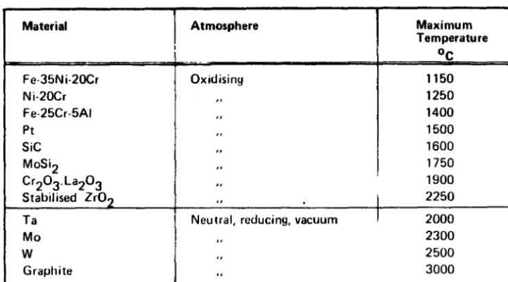
Fu rnHII and Heating Elements
Industrial furnaces, combustion chamber I
Electrical heating elements, carbide Electrical heating elements, zirconia Electrical heating elements, graphite Infrared gasradiators
Po war generation
HTR •. steam generation HTR, He turbine HTR, process heat
High temperature fuel cells
Therm ionic converters I
Fusion reactor (blanket ) !
MHO open cycle (coal, gas)
I
A arOip!CI Applications I
I
L
I
Chemical rockets I
I
Reentry, controlled, stagnation point I
Reentry, controlled. wings
i
I " , aeroballistic (shock front)
I
lght
Lamps, carbon, filament
" , tungsten filament " , halogen
{°C) 200 600 1000 2000 6000 10.000
[image:30.572.67.498.57.699.2]=..
~..
c Gl c&
E8
101~---~---r---.---.---.---~
---.
---
··---+·
-·--··---·--t---"STRESSED"
r
"UNSTRESSED"
!0
0
500
1000
1500
2000
3000
Temperature
of
components
[°CJ
Fig.
3.1/2
Typical
component
/de
ranges
of
some
actual
high-temperature
The main applications of high-temperature materials in the ad-vanced sense described above are those for which a high thermal conductivity is a major requirement: in the first place all high-temperature heat-transfer systems .. Purther concerned are all applications in which either space, weight, cooling or speci-fic strength requirements forbid the use of "function separa-tion" (except coatings) : in particular mechanical power engi-nes. The application having the highest material temperature at lon~-time steady-state operation is the area of electric heating elements. In contrast to most other applications, heating element materials have a higher rather than lower
temperature than their environment, and these temperatures can be so high that only stress-free and controlled-atmosphere ope-ration is possible. Heating elements therefore represent an extreme case of an advanced high-temperature materials appli-cation, one of the two material functions being relaxed to maximize the other.
Temperatures higher than those of heating elements are invol-ved in certain manufacturing processes (carbides, graphite), some types of flame, explosions (including nuclear), MHO gene-rators, special glow lamps and, as shown by fig. 3.1/1 some aerospace systems.
To assess these systems in the light of the above approach, reference is made to a technological parameter which is uni-quely able to quantify the performance of materials: the high-temperature service life of components. Apart from the general goals of engineering design corrmton to all technologies, i.e. proper operation and economy, component life is a particu-larly sensitive parameter of high-temperature design and deve-lopment, and can be considered as an important indicator of the
technological state and the potential for further development of an application. Moreover it can be used to classify appli-cations in terms of ranges which have technological relevance.
Figure 3.1/2 shows such ranges of component life for some high-temperature applications, and it appears that the techno-logy of processes, engines and systems having unlimited opera-tion period achieves minimum component lives of the order of several thousand hours. This class of application must be distinguished from applications having service lives of some
100 hours or less, down to even some ndnutes.
These "short-time" applications, which also include those
The short service life of experimental systems like MHD gene-rators and ceramic gas-turbine components are not inherent, but reflect the current state of development of these appli-cations. The prime goal of their development is indeed the extension of component life to an economically attractive length.
Apart from these experimental development areas, other short-time applications have characteristics and development goals very different from the general scope of the White Book, so that they are left out of consideration.
3.1.3 Temperature range
The life-temperature relationship of technologies shown in fig. 3.1/2 suggests that practical limits exist beyond which extension has not yet taken place. This appears to be true for applications in which components operate under. mechanical
stress, as well as for those without mechanical stress. Appli-cations having, for example, more severe environmental condi-tions, thermal or mechanic load variations and shocks, or more severe reliability requirements and failure acceptance crite-ria, have much lower values than the apparently "best" appli-cations shown in the figure. A transition area between the
line marked "stressed" and the line marked "unstressed" must exist, but scarcity of data and the lack of a universal "load" parameter to replace the unquantified parameter "stress", make a more detailed evaluation too difficult.
Taking these aspects into account and neglecting precise quantitative analysis, one can consider the relation between the different applications shown in fig. 3.1/2 as realistic. It is certain that a large number of other applications could be added, in particular at the low-temperature end. It appears however that the critical development goal is to expand beyond the 1000°C/100000 hours range, since this is of practical
technological importance, as demonstrated by the nuclear process-heat development. The technologies which are the clo-sest to this area are steam reformers and gas turbines.
To draw a temperature range limitation not affecting the
coherence between these areas, a line should be drawn between these technologies and steam power generation. 'I·he temperature r~nge definition based upon applications should therefore
refer to material temperatures higher than those at which components of the conventional steam cycle are operating.
On the basis of the limitation used here, therefore, the lower limit of the high-temperature range is at approximately 600°C. With respect to materials, this definition leads to the exclu-sion of low-alloy ferritic steels from high-temperature mate-rials.