multi-stage interference cancellation scheme for orthogonal frequency division multiple access uplink systems with carrier frequency offsets.
White Rose Research Online URL for this paper: http://eprints.whiterose.ac.uk/109521/
Version: Accepted Version
Article:
Fa, R and Zhang, L (2013) Generalised grouped minimum mean-squared errorbased multi-stage interference cancellation scheme for orthogonal frequency division multiple access uplink systems with carrier frequency offsets. IET Communications, 7 (7). pp. 685-695. ISSN 1751-8628
https://doi.org/10.1049/iet-com.2012.0285
(c) The Institution of Engineering and Technology 2013. Personal use of this material is permitted. Permission from IEEE must be obtained for all other uses, in any current or future media, including reprinting/republishing this material for advertising or promotional purposes, creating new collective works, for resale or redistribution to servers or lists, or reuse of any copyrighted component of this work in other works.
[email protected] https://eprints.whiterose.ac.uk/
Reuse
Items deposited in White Rose Research Online are protected by copyright, with all rights reserved unless indicated otherwise. They may be downloaded and/or printed for private study, or other acts as permitted by national copyright laws. The publisher or other rights holders may allow further reproduction and re-use of the full text version. This is indicated by the licence information on the White Rose Research Online record for the item.
Takedown
If you consider content in White Rose Research Online to be in breach of UK law, please notify us by
Generalized Grouped MMSE Based
Multi-stage Interference Cancellation Scheme
for OFDMA Uplink Systems with CFOs
Rui Fa
†and Li Zhang
‡Abstract
In uplink OFDMA systems with CFOs, there always be a dilemma that high performance and
low complexity can not be obtained simultaneously. In this paper, in order to achieve better
trade-off between performance and complexity, we propose a grouped minimum mean squared error
(G-MMSE) based multi-stage interference cancellation (MIC) scheme. The first stage of the proposed
scheme is a G-MMSE detector, where the signal is detected group by group using banks of partial
MMSE filters. The signal group can be either user based or subcarrier based. Multiple novel IC units
are serially concatenated with the G-MMSE detector. Reusing the filters in the G-MMSE detector
significantly reduces the computational complexity in the subsequent IC units as shown by the complexity
analysis. The performance of the proposed G-MMSE-MIC schemes are evaluated by theoretical analysis
and simulation. The results show that the proposed schemes outperform other existing schemes with
considerably low complexity.
Index Terms – Orthogonal frequency division multiple-access (OFDMA), interference cancella-tion (IC), multiuser interference (MUI), carrier frequency offset (CFO).
I. INTRODUCTION
Orthogonal frequency division multiple access (OFDMA) has recently attracted a great deal of research interest due to its potential of high spectral efficiency, inherent immunity to multipath
†Dr. Rui Fa is with the University of Liverpool, Liverpool, Email: [email protected];
‡Dr. Li Zhang is with School of Electronic and Electrical Engineering, University of Leeds, Leeds, LS2 9JT, United Kingdom.
fading and simplified equalization [1]–[11]. It has been selected as one of the physical-layer
multiple-access technologies in the recent wireless metropolitan area network (MAN) standard IEEE 802.16 [12] and 3GPP-LTE [13]. Despite its appealing features, OFDMA is extremely sensitive to carrier frequency offsets (CFOs), which may be induced by Doppler effects and/or a misaligned local oscillator. The presence of CFOs results in the loss of mutual orthogonal-ity among subcarriers, produces both intercarrier interference (ICI) and multiuser interference
(MUI), and degrades the system performance [8], [9]. Counteracting CFOs in OFDMA uplink is particularly difficult mainly due to two reasons. Firstly, CFO estimation is a difficult job in uplink OFDMA, apparently due to the presence of multiple CFOs [3], [8], [14], [15]. Secondly, the detection is also challenging even given perfect CFO estimation, because the compensation of one user’s CFO would misalign other users and cause severe MUI [5], [9]–[11], [16]–[19]. It is
a common practice to employ a particular synchronization policy where the CFOs are estimated during the downlink phase, then returned by a downlink control channel and compensated at each userbefore uplink transmission [20]. However, even with this approach, residual frequency errors may be present in the received uplink signals at the base station (BS) due to estimation
errors and/or Doppler shifts. In this case, novel synchronization and compensation algorithms are still required at the BS [7], [10].
In this paper, we focus on the compensation assuming that CFO estimation has been ac-complished [14], [15]. There are a few schemes proposed for detection in uplink OFDMA systems with CFOs. In [16], the CLJL scheme (named after the four authors’ initials) was
proposed to compensate the CFOs after the discrete Fourier transform (DFT) using circular convolution rather than before the DFT. Apart from the CLJL scheme, other schemes can be roughly grouped into two categories: one is for interference cancellation (IC) schemes including parallel interference cancellation (PIC) using circular convolution, such as Huang-Letaief Circular Convolution (HLCC) [10] and weighted linear PIC (WLPIC) [11] schemes, and also including
selective PIC (SPIC) [9] and successive interference cancellation (SIC) schemes [17]; the other is for minimum mean squared error (MMSE) based schemes [5], [18], [19]. On one hand, most of
Although [18], [19] proposed banded method and iterative implementation to approach MMSE
scheme, the computational complexity is still high. Moreover, both IC schemes and MMSE-based schemes degrade much with the generalized carrier assignment scheme (GCAS), which is the current trend in OFDMA due to its flexibility for dynamical resource allocation [7], [10].
In this paper, we propose a grouped minimum mean squared error (G-MMSE) based multi-stage interference cancellation (MIC) scheme for the uplink OFDMA systems with CFOs, in order to achieve better trade-off between performance and complexity. Although group-wise interference cancellation (GIC) has been discussed in the CDMA and MIMO systems [21], [22], there are many questions to be answered when applying the group-wise IC concept in the uplink
OFDMA systems with CFOs, for example, how to form a group, how to cancel interference and what is the theoretical performance. The GIC schemes for CDMA and MIMO systems are similar, as a MIMO spatial multiplexing system can be equivalently viewed as a CDMA system. The code signatures (CDMA) or the spatial signatures (MIMO) are broken into many small groups while in OFDMA systems, there is no such signature. Thus, the GIC scheme has
to be tailored according to the specifications of the OFDMA system. To our best knowledge, there is no contribution to the group-wise IC for the uplink OFDMA systems in the literature so far. Here, we propose a scheme which consists of multiple stages. The first stage is a G-MMSE detector, where the signal is detected group by group using banks of partial G-MMSE filters. The grouping can be user-based and subcarrier-based. Multiple novel IC units, which
are different with the conventional SIC and PIC schemes, are serially concatenated with the G-MMSE detector. Because the filters in the G-MMSE detector can be reused in the subsequent IC units, the computational complexity is greatly reduced according to the complexity analysis. Furthermore, the bit error probability (BEP) performance of the proposed scheme is theoretically
analysed and validated by simulations. The numerical results show that the proposed G-MMSE-MIC schemes outperform other existing schemes with considerable low complexity.
The main contributions we have made in our paper are listed as follows
1) A G-MMSE detector is proposed. Both user-grouped (UG) and subcarrier-grouped (SCG) methods are described and investigated for the OFDMA uplink system.
2) An IC unit, which is different with the conventional SIC and PIC schemes, is proposed. 3) Multiple IC units are serially concatenated with the G-MMSE detector. The computational
the subsequent IC units.
4) The complexity analysis and theoretical BEP performance analysis are carried out.
The rest of paper is organized as follows. Sec. II presents the uplink OFDMA system model. The G-MMSE algorithm is developed for the uplink OFDMA systems and the UG and SCG methods are presented in Sec. III. Sec. IV describes the proposed IC units and MIC scheme. Subsequently, Sec. V carries out the complexity analysis and theoretical performance analysis.
Finally, the simulation results and conclusions are given in Sec. VI and VII, respectively.
II. SYSTEMMODEL FOR OFDMA UPLINK
The OFDMA uplink system under consideration consists of one base station (BS) and K user terminals communicating with the BS simultaneously. For simplicity, we assume that both time synchronization and sampling are ideally performed as [10] did. Reader who are interested in
the algorithms achieving time synchronization may refer to [8] and references therein. Suppose that N subcarriers are used for transmitting signal and are evenly divided into K′ (K′ ≥ K)
subchannels. To avoid aliasing problem at the receiver, a number N0 of null subcarriers are placed at both edges of the signal spectrum. Each subchannel contains Nc = (N −2N0)/K′
subcarriers. Denoting the i-th block of frequency-domain modulated symbols sent by the k-th user as sk(i), where k ∈ {1,2, ..., K}, and the j-th entry of sk(i) is non-zero only if the j-th subcarrier is assigned to the k-th user. Define a mapping vector Mk ={Mj
k|j = 1, ..., N} to
indicate the subcarrier mapping for the k-th user, where the subcarrier assignment is given by Mjk =
1 j is assigned to the k-th user 0 j is not assigned to the k-th user .
(1)
We also define an index vector Ik with the length of Nc to record the indices of subcarriers
assigned to the k-th user. For the subband carrier assignment scheme (SCAS), the subcarriers assigned to one user are adjacent while for the GCAS, they are assigned in a random fashion. A
cyclic prefix (CP) of length Np is appended to eliminate the inter-block interference (IBI). The
resulting signaluk(i) with the length of N +Np is transmitted over the channel. The multipath
channel, which is a tapped delay line (TDL) model, is assumed static over an OFDM block but it may vary from block to block. Let hk(i) = [h0k(i), h1k(i), ..., h
Nh−1
k (i)]T denote the discrete-time
operator and Nh is the channel length, which is usually less than or equal to(Np+ 1). Without
loss of generality, we drop the block index i in the following text for simple notation. After serial-to-parallel (S/P) conversion and the CP removal, anN dimensional vectoryis formed. Let
ϵk denote the CFO normalized by subcarrier spacing between the k-th user and the BS, which
is uniformly distributed over the range of [−0.5,0.5). The received OFDMA signal vector y in the presence of CFOs is mathematically written as
y=
K ∑
k=1
Γ(ϵk)HkFHsk+n, (2)
where
• Γ(ϵk) =diag(1, ej2πϵk/N, ..., ej2πϵk(N−1)/N);
• F is theN-point discrete Fourier transform (DFT) matrix with entriesFp,q = √1N exp
(−j2πpq N
)
, (0≤p, q ≤N −1) and (·)H denotes the Hermitian transpose;
• Hk is the circulant channel convolution matrix corresponding to the k-th user;
• nis circularly symmetric white Gaussian noise with zero-mean and covariance matrixσn2IN,
where IN is the identity matrix of order N and σn2 is the noise power.
According to [23], we note that Hk = FHD(Hk)F, where D(·) is diagonal matrix operator and Hk is the channel frequency response (CFR), which is obtained by F h¯ k, where F¯ is the
first Nh columns of F.
After applying DFT on (2), the frequency-domain received signal vectorY can be written as
Y =
K ∑
k=1
FΓ(ϵk)FHD(Hk)sk+F n,
=Πs+v,
(3)
where
• Π=∑Kk=1FΓ(ϵk)FHD(Hk)D(Mk);
• s=∑Kk=1sk;
• v =F n is the frequency-domain noise vector.
III. GROUPEDMMSE ALGORITHM
zf is given by
zf =WHf Y, (4)
where
Wf = (
ΠΠH + σ 2
n
σ2
s
IN )−1
Π, (5)
where subscript f denotes the FMMSE scheme and σ2
s is the averaged power of the transmitted
signal on one subcarrier. The detected soft symbolszf finally can be demodulated to bit streams.
Due to the operation of matrix inversion, the FMMSE algorithm is too complex for practical use, especially when the system size is large. For this reason, [18], [19] proposed banded method and iterative implementation to approach FMMSE scheme, however, their computational complexity is still high. In this paper, we propose a low-complexity G-MMSE algorithm, which
detects the signal group by group using banks of small size filters. Note that the G-MMSE is not a true MMSE filter but a simplified MMSE or partial MMSE filter. Considering the truth that the most impactive MAI comes from the neighbouring subcarriers, the G-MMSE scheme ignores part of MAI by employing small size filters to achieve a trade-off between performance and complexity. The signal can be grouped according to either associated users, termed as
user-grouped (UG) method or adjacent subcarriers termed as subcarrier-grouped (SCG). In the subsequent subsections, we will introduce them in details, respectively.
A. User-Grouped Method
In the UG method, we organize the subcarriers allocated to the same user into one group, and apply MMSE. Thus, the detection of the k-th user is mathematically given by
zk =WHkYk,
Wk = (ΠkΠHk +
σ2
n
σ2
s
INc)−
1 Πk,
Πk =Π(Ik,Ik),
Yk =Y(Ik),
(6)
where {Wk = {wk,n′|n′ = 1, ..., Nc}|k = 1, ..., K} are K banks of filters where wk,n′ is the
filter for the k-th user’s n′-th subcarrier. z
k is the detected soft symbol vector of the k-th user.
The mapping between the overall subcarrier index n and {k, n′} is given by
The entries ofΠk ∈ CNc×Nc andY
k∈ CNc×1 are selected fromΠandY, respectively, according
to the index vector Ik, which records the indices of subcarriers assigned to the k-th user. Fig. 1 illustrates the entry selection of Πk for both the SCAS and the GCAS. Note that Fig. 1 (a) is
shared by the SCG method regardless of the CAS, which will be detailed in the next subsection. In this case, for example, if the j-th, m-th andn-th subcarriers (recorded in Ik) are assigned to thek-th user, the entries marked with the cross shadow in the figure are selected. The difference between the SCAS and the GCAS is that Πk for the SCAS is the sub-matrix on the diagonal
of Π while the entries of Πk for the GCAS are randomly distributed in Π.
B. Subcarrier-Grouped Method
In the SCG method, we organize adjacent subcarriers into groups. Suppose that the number of subcarriers in a group isNsc and the number of groups then isG=N/Nsc. Thus, theg-th group
contains the indices of subcarriers from(g−1)Nsc+ 1togNsc whose index vector is denoted as
Ig, g = 1, ..., G, and there is no difference between the detectors for the SCAS and the GCAS scenarios. Without loss of generality, the detection of the g-th group is mathematically given by
zg =WHg Yg,
Wg = (ΠgΠHg +
σ2
n
σ2
s
INsc)−
1 Πg,
Πg =Π(Ig,Ig),
Yg =Y(Ig),
(7)
where zg denotes the detected soft symbol vector with the order of Nsc for the g-th group,
where g = 1, ..., G the entries of Πg ∈ CNsc×Nsc and Yg ∈ CNsc×1 are selected from Π and Y,
respectively, according to the index vectorIg, which records the indices of adjacent subcarriers grouped into the g-th group. {Wg ={wg,n′|n′ = 1, ..., Nsc}|g = 1, ..., G} are G banks of filters
where wg,n′ is the filter for the n′-th subcarrier in the g-th group. The mapping between the
overall subcarrier index n and {g, n′} is given by
n =Ig(n′).
The entry selection of Πg is illustrated in Fig. 1 (a) where the entries marked with the cross
shadow are selected. Note that {Πg|g = 1, ..., G} are G sub-matrices of Π and locate on its
The explicit differences between the UG-MMSE and SCG-MMSE detectors, which are
re-flected in equations (6) and (7), are the subscripts k/g and the index vector Ik/Ig. But the
inherent difference between these two algorithms, which we are claiming, is the way to organize a group. Different grouping method would bring different features into the algorithm.
IV. PROPOSED MULTI-STAGE INTERFERENCECANCELLATION SCHEME
Besides the advantage of low-complexity which thanks to the small size matrix inversion,
another advantage of the G-MMSE algorithm is that we can reuse the filters{Wk|k = 1, ..., K}
for the UG method or{Wg|g = 1, ..., G} for the SCG method in the subsequent IC stages. As a
result, the system performance can be greatly improved, without causing significant complexity increase. In this section, we will discuss the proposed UG-MMSE-MIC and SCG-MMSE-MIC schemes with the novel IC strategy, respectively.
A. UG-MMSE-MIC scheme
The diagram of the proposed multi-stage interference cancellation scheme is depicted in Fig. 2, which can be shared by both the UG-MMSE-MIC and the SCG-MMSE-MIC schemes. In the UG method case, the proposed UG-MMSE-MIC scheme concatenates the UG-MMSE detector, shown as W1, ...,WK, with multiple IC units, whose pseudo code is given in Table I (a). Each
IC unit reusesK banks of filters{Wk|k= 1, ..., K}in the UG-MMSE detector. Letsˆ(km)denotes the restored symbol vector obtained by
ˆ
s(km)= Restore(z(km)), (8) where Restore(z(km)) denotes the operator of restoring the symbol from the detected symbol
z(km), which contains demodulation and remodulation operations. The restored symbol vector ˆ
subtracting the reconstructed signal of all other users from the received frequency-domain signal
vector, the signalY(m), which theoretically contains only the k-th user is obtained. Reusing the UG-MMSE detector Wk on Y(km), which is formed by selecting entries from Y(m) according
to Ik, we can get the detected symbol vector for the k-th user. It is worth noting that the 7-th line of the pseudo-code not only sends the restored symbol vector to the output of current IC stage, which will be used in the next IC unit, but also updates the restored symbol vector of
current IC unit, which will improve the subsequent detection of other users. This makes an important difference between our proposed MIC scheme with the conventional PIC scheme. Although conventional PIC scheme has less latency, our proposed UG-MMSE-MIC scheme can provide much better performance. Note that the HLCC scheme, which applies the conventional multi-stage PIC structure, will be compared with the proposed scheme in the simulations.
B. SCG-MMSE-MIC scheme
For the SCG method case, as depicted in Fig. 2, the proposed SCG-MMSE-MIC scheme concatenates the SCG-MMSE detector, shown as W1, ...,WG, with multiple IC units, whose
pseudo code is given in Table I (b). Let ˆs(gm) denote the restored symbol vector for the g-th group at the output of the m-th IC unit, which will be sent to the (m+ 1)-th IC unit, where
m = 1, ..., M and M is the total number of IC units. ˆs(0)g is the restored symbol vector for the
g-th group from the SCG-MMSE detector, which is sent to the first IC unit. In Table I (b), we formalize the pseudo code of them-th IC unit, where without loss of generality, we take theg-th group as example. Similar with the UG-MMSE-MIC scheme, the 7-th line of the pseudo-code not only sends the restored symbol vector to the output of current IC stage, which will be used in the next IC unit, but also updates the detected symbol vector of current IC unit, which will improve the subsequent detection of other groups.
V. THEORETICAL ANALYSIS
In this section, both complexity analysis in terms of the number of multiplications and additions and bit error probability (BEP) analysis according to the signal-to-interference-plus-noise ratio (SINR) are carried out. The complexity of both the UG-MMSE-MIC and SCG-MMSE-MIC schemes are analysed, respectively, due to their different nature of processing. For
because the procedures for BEP analysis of the UG method is exactly the same with the SCG
method.
A. Complexity Analysis
The computational complexity of our proposed UG-MMSE-MIC and SCG-MMSE-MIC schemes in terms of the number of multiplications and additions are is compared with other existing
schemes, namely the CLJL [16], the HLCC [10], the FMMSE and the BMMSE schemes [18], and given in Table II. In these schemes, the CLJL is the simplest scheme with the complexity of O(KN2
c), however it provides the worst detection performance as will be shown in the
simulations. The HLCC and the proposed UG-MMSE-MIC have comparable computational complexity, which is O(M KN2). The proposed SCG-MMSE-MIC scheme has complexity of O(M GN2), which is related to the number of groups. The FMMSE scheme has the highest complexity ofO(N3)and the BMMSE scheme, whose complexity of O(N τ2)is determined by the parameter τ, is a complexity efficient algorithm to approximate the FMMSE scheme. Note that the complexity of the CLJL, the HLCC and the proposed UG-MMSE-MIC algorithms are
related to the parameters K and Nc. This means that once the number of users and the number
of subcarriers allocated to a single user are fixed at the transmitter side, the complexity of the receiver using these three algorithms is fixed, as shown in Table II. While the complexity of
the proposed SCG-MMSE-MIC scheme, which is independent to K and Nc, is determined by
flexible parameterNsc and corresponding G, which can be selected to achieve the best trade-off.
Unlike the above algorithms, the complexity of the proposed SCG-MMSE-MIC scheme is flexible
since it is determined by Nsc and corresponding G rather than K and Nc. Thus, in this case,
we may have the freedom to achieve the best trade-off between performance and the complexity
by selecting Nsc. We compare the proposed schemes with the existing schemes in two different
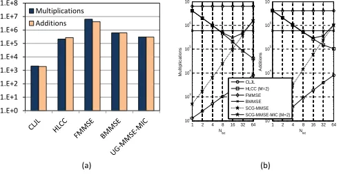
ways. Firstly, the required operations of multiplications and additions for the proposed
UG-MMSE-MIC scheme and other existing schemes are illustrated using the bar chart in Fig. 3 (a) with a system setting of N=128, K=8,Nc=16. According to [10], [18], the number of IC stages
M is equal to 2 and τ is set to 30 to provide reasonable performance. Note that although the complexity of the proposed scheme is slightly higher than the HLCC scheme, as will be shown in the simulations, it outperforms other existing schemes including the FMMSE scheme. Secondly,
SCG-MMSE-MIC scheme and other existing schemes are illustrated in Fig. 3 (b) with a system setting of
N=128. The number of IC stages M and τ are also equal to 2 and 30, respectively. It is worth emphasizing that in the figureNsc for all algorithms except the SCG-MMSE-MIC representsNc
and only the value of Nsc for the SCG-MMSE-MIC scheme can be chosen at the receiver end.
For example, Nsc=4 in the figure means that Nc=4 and K=32 for all other algorithms while the
SCG-MMSE-MIC scheme can configure the parameters to achieve the best trade-off between
the performance and the complexity regardless of K and Nc. As illustrated in Fig. 3 (b), for
example, for a system with 32 users (K=32,Nc=4), the complexity of the HLCC algorithms has
Nsc=4 with 9.86E+5 multiplications and 1.05E+6 additions, while the SCG-MMSE-MIC scheme
can employ Nsc = 16 so that it only requires 3.05E+5 multiplications and 2.95E+5 additions.
B. Performance Analysis
This subsection presents theoretical performance analysis of the MMSE detector and G-MMSE-MIC scheme. The analysis is motivated by the performance studies of PIC in [24] where the error probability is analysed in terms of the SINR. In order to present the complex analysis procedure clearly, we divide the analytical task into three steps: the first step is the BEP analysis of the G-MMSE detector, the second is the BEP analysis of the G-MMSE-MIC schemes with
perfect IC, and the third is the BEP analysis of the G-MMSE-MIC schemes with IC errors. Since the main difference between the UG-MMSE and SCG-MMSE schemes is the use of the subscriptk/g and the index vector Ik/Ig, which would not affect the performance analysis, we only present here the analysis of the SCG-MMSE detector and SCG-MMSE-MIC scheme.
1) SCG-MMSE Detector: Let us denote the average BEP of the G-MMSE detector as ¯PG, which is given by
¯
PG = 1
N
N ∑
n=1 [∫
Hn ∫
ϵ
PeGn(Π)p(Hn)p(ϵ)dHndϵ ]
,
¯
PG = 1
N N
∑
n=1 [∫
Hn
∫
ϵ
PeGn(Π|Hn,ϵ)p(Hn)p(ϵ)dHndϵ
]
, (9)
where PeGn(Π|Hn,ϵ) denotes the BEP of the G-MMSE detector on the n-th subcarrier
condi-tioned on the CFR H and the CFOs ϵ, since Π is determined by H and ϵ according to (3),
subcarrier and the CFOs, respectively. Because it is impossible to derive a close form to evaluate
the error probability, our method is to average the EP over the channel and CFOs as many as
possible in a Monte-Carlo fashion. we employ a semi-theoretical method to divert the problem
from calculating BEP conditioned on the PDFs of channel and CFOs theoretically. We generate
L sets of channel coefficients and CFOs randomly as we did for Monte-Carlo simulation. The
semi-theoretical BEP is then calculated directly rather than counting the BER. The final BEP is
averaged over L sets of channels and CFOs. If L → ∞, the semi-theoretical analysis will be
approximated to theoretical one. Note that for givenH and the CFOsϵ, Πis fixed. Thus, since the CFOs are uniformly distributed, the average BEP P¯G can be approximated to
¯
PG ≈ 1
N N ∑ n=1 [∫ Hn
PeGn(Π)p(Hn)dHn
]
,≈ 1 N N ∑ n=1 [ lim L→∞ L ∑ i=1
PeGn (Π(i))p(Hn(i))
]
,
¯
PG≈ 1
N N ∑ n=1 [ lim L→∞ 1 L L ∑ i=1
PeGn(Π(i)|Hn(i),ϵ(i))
]
, (10)
where Π(i) is for the i-th block transmission.
As is well known that in a multicarrier system, a frequency-selective fading channel is viewed
as several independent frequency-flat fading subchannels on individual subcarriers. We assume that the fading amplitude of each frequency-flat fading subchannel satisfies Rayleigh distribution. In this case, the frequency-domain received signal vector Y(i) for the i-th block in (3) can be further re-written as
Y(i) =
S
g,n′(i)
z }| {
Π(Ig(n′))(i)s(Ig(n′))(i)
+
VG
g,n′(i)
z }| {
N ∑
˜
n= 1
˜
n̸=Ig(n′)
Π(˜n)(i)s(˜n)(i) +v(i),
(11)
where Π(n)(i)denotes the n-th column of the matrix Π(i)and s(n)(i)denotes the n-th element in the vector s(i), the frequency-domain received signal of the n′-th subcarrier in the g-th
group is denoted as Sg,n′(i)and the corresponding interference caused by other subcarriers plus
noise is denoted as VGg,n′(i). Let us assume that the interference-plus-noise VGg,n′(i)is Gaussian
¯ PG= 1
N N ∑ n=1 [ lim L→∞ 1 L L ∑ i=1 Q (√
2 E[|w
H
n(i)Sn(i,Ig)|2]
E[|wH
n(i)VGn(i,Ig)|2 ]
)
p(Hn(i))
]
(15)
model, the output of the SCG-MMSE detector for then′-th subcarrier in theg-th group is written
as
zg,n′(i) = wHg,n′(i)Yg(i)
=wHg,n′(i)Sg,n′(i,Ig) +wHg,n′(i)VGg,n′(i,Ig).
(12)
According to the mapping between n and{g, n′}, the SINR for the n-th subcarrier can be given
by
γnG|Π(i) = E
[
|wHn(i)Sn(i,Ig)|2] E[|wH
n(i)VGn(i,Ig)|2
], (13)
whereE[·]donotes the expectation operator. According to [24], [25], the BEP PeGn(Π(i)|Hn(i),ϵ(i))
can be easily obtained by
PeGn(Π(i)|Hn(i),ϵ(i)) =Q( √
2γG
n|Π(i)), (14)
where γG
n|Π(i) denotes the SINR of the symbol carried on the n-th subcarrier with given Π(i) and
Q(x), √1 2π
∫ ∞
x
e−t2/2dt.
By substituting (13) into (14) and then (10), we can obtain the average BEP ¯PG for the
SCG-MMSE detector as (15).
2) SCG-MMSE-MIC Scheme With Perfect IC: In the perfect IC case, the interference from other groups are perfectly cancelled, thus, the frequency-domain post perfect IC (PPIC) signal vector YPPIC can be written as
YPPIC(i) =
S
g,n′(i)
z }| {
Π(Ig(n′))(i)s(Ig(n′))(i)
+
VPPIC
g,n′(i)
z }| {
Nsc ∑
˜
n= 1
˜
n̸=n′
Π(Ig(˜n))(i)s(Ig(˜n))(i) +v(i).
¯
PPPIC = 1
N N ∑ n=1 [ lim L→∞ 1 L L ∑ i=1 Q (√
2 E[|w
H
n(i)Sn(i,Ig)|2]
E[|wH n(i)V
PPIC
n (i,Ig)|2 ]
)
p(Hn(i))
]
(18)
The SINR of the n-th subcarrier for the SCG-MMSE-MIC scheme with perfect IC can be given by
γPPIC
n|Π(i) =
E[|wHn(i)Sn(i,Ig)|2] E[|wH
n(i)VPPICn (i,Ig)|2
]. (17)
By substituting (17) into (14) and then (10), we can further obtain the average BEP of the
SCG-MMSE-MIC scheme with perfect IC, as given by (18).
3) SCG-MMSE-MIC Scheme With IC Errors: The interference will be even enhanced when IC errors (ICE) occur in theN−Nsc cancelled symbols. Let us define error event sets {Ej|j =
0,1, ..., N −Nsc} for the case when j errors out of N −Nsc symbols occurred in the current
IC stage. The number of error events in the error event set Ej is Ne =C(N −Nsc, j), that is
Ej ={ecj|c= 1, ..., Ne}, whereC(n, r)denotes the combination operator as (
n r
)
andec
j denotes
the c-th error event in the error event set Ej. We can write the BEP of the SCG-MMSE-MIC
scheme with ICE PeICEn,m(Π(i)|Hn(i),ϵ(i))on then-th subcarrier in them-th IC unit for the i-th
block. For simplicity, we drop Hn(i),ϵ(i) and write PeICEn,m(Π(i)) as
PeICEn,m(Π(i)) =
N−Nsc ∑
j=0
Ne ∑
c=1
PeICEn {Π(i)|ecj}Pm−1{ecj}, (19)
where Pm−1{ecj} is the probability for the error event ecj, which can be calculated based on the
BEP from the (m −1)-th IC stage PeICE
n,m−1(Π(i)). Note that for the first IC stage (m = 1), PeICEn,m−1(Π(i)) is PeGn(Π(i)). PeICE
n {
Π(i)|ec j }
is the BEP conditioned on the error event ec j,
which can be written as
PeICEn {Π(i)|ecj}=Q(√2γICE
n|Π(i),ec
j), (20)
where γICE
n|Π(i),ec
j is the SINR conditioned on the error event e c
j. To calculate γnICE|Π(i),ec
j, we can
write the frequency-domain signal vector conditioned on the error event ec j as Y
ICE
ec
j (i) in (21),
where the second item of VICEg,n′|ec
j(i) denotes the extra interference caused by the error event e c j.
Thus, γICE
n|Π(i),ec
j is given by
γICE
n|Π(i),ec j =
E[|wHn(i)Sn(i,Ig)|2] E
[
|wH n(i)V
ICE
n|ec
j(i,Ig)|
2].
YICEec j (i) =
S
g,n′(i)
z }| {
Π(Ig(n′))(i)s(Ig(n′))(i) +
VICE
g,n′|ecj(i)
z }| {
Nsc ∑
˜
n= 1
˜
n̸=n′
Π(Ig(˜n))(i)s(Ig(˜n))(i) +∑ j
2Π(nj)(i)s(nj)(i) +v(i).
(21)
Similar with (9), we can write the average BEP of the proposed SCG-MMSE-MIC scheme for the m-th IC unit P¯ICEm as
¯
PICEm = 1
N
N ∑
n=1
[
lim
L→∞
1
L
L ∑
i=1
PeICEn,m(Π(i))p(Hn(i))
]
. (23)
To explain our performance analysis clearly, we take an example of a small system. Let us consider a system with N=8 subcarriers, Nsc=4 subcarriers in each group and G=2 groups.
Suppose we are calculating the BEP for the third subcarrier (n=3), which is supposed to locate in the first group. Thus, the IC errors will only occur in the second group and the possible number of errors j is from 0 to N − Nsc, in this case, is 4. When there are j erroneous
subcarriers out of 4 subcarriers,Ne will be (
4
j
)
possible combinations of erroneous subcarriers, say j=2, then Ne=6. The error event set E2 contains 6 error events {ec2|c = 1, ...,6} where {e1
2 = {5,6}, e22 = {5,7}, e32 = {5,8}, e42 = {6,7}, e52 = {6,8}, e62 = {7,8}}. To calculate PeICE3,1(Π(i)) for the first IC stage (m=1), we have to take all error event sets into account and consider the BEPs of all the error events based on PeGn(Π(i)) as a priori probabilities. Based on a priori probability considering 1−PeGn(Π(i)) for correct subcarriers and PeGn(Π(i)) for erroneous subcarriers, we obtain the probability of the error event P0{ecj}, for example, P0{e12} is obtained by
PeG5(Π(i))PeG6(Π(i))(1−PeG7(Π(i)))(1−PeG8(Π(i))).
Using (20), (21) and (22), we can obtain PeICE3 {Π(i)|ec j }
conditioned on the error event ec j. By
calculating error probabilities conditioned on all error events PeICE3 {Π(i)|ec j }
and their a priori
probabilities Pm−1{ecj} where j = 1, ..., N −Nsc, c= 1, ..., Ne, and substituting them into (19),
VI. SIMULATIONRESULTS
In this section, numerical results of the proposed schemes including both the
UG-MMSE-MIC and SCG-MMSE-UG-MMSE-MIC schemes are reported. Consider an OFDMA uplink system with
N=128 subcarriers and both uncoded binary shift keying (BPSK) and quadrature phase-shift keying (QPSK) modulations, which is operating in the 5 GHz frequency band and the subcarrier spacing equal to 10.94 kHz. Considering that N0 ̸= 0 zero carrier guards placed at both edges of signal spectrum in the practical system improve the performance, we investigate
the system with N0 = 0 as the worst case. That means each frame contains 128 symbols. The channel coefficients and CFOs change frame by frame. Both the SCAS and the GCAS are employed as the subcarrier allocation scheme for the UG-MMSE-MIC scheme and only the GCAS is considered for the MMSE-MIC scheme because with the SCAS, the SCG-MMSE-MIC scheme is similar with the UG-SCG-MMSE-MIC scheme. We define two scenarios for
the investigation: scenario one employsK = 8 andNc = 16, and scenario two employs K = 32
and Nc = 4. The channel between each user and the BS is assumed invariant within one block,
but may change independently from one block to the next. The length of the channel Nh is 8
and the average power of each tap follows exponential power delay profile given by
E[|hlk|2] =e−l/Nh, 0≤l ≤N
h−1, (24)
where E[·] denotes the expectation operator. The length of CP is Np=8. The normalized CFOs
are randomly selected from [−0.5,0.5). We evaluate the performance of the proposed schemes in terms of the bit error rate (BER) against the signal-to-noise ratio (SNR). The SNR is defined as
SNR= 10 log10 σ 2
s
σ2
n
. (25)
All simulation results are averaged over 5000 independent frame iterations. In the rest of this section, we will firstly show the BER against SNR performance of the proposed schemes and other existing schemes in the system with perfect CFO estimation for both BPSK and QPSK modulations. Secondly, we will show the performance of the proposed schemes in the system
A. With Perfect CFO Estimation
In this part, we assume that the CFO estimation is perfect. For the proposed UG-MMSE-MIC
scheme, we firstly consider the uplink OFDMA systems employing the SCAS and the BPSK signal. Fig. 4 compares the BER performance of all the discussed schemes for the OFDMA uplink system with the scenario one. It is shown that the proposed UG-MMSE-MIC scheme has superior performance. The performance at the first IC unit of the proposed scheme has slightly better performance than other existing schemes, even including the FMMSE scheme. There is
more than 1 dB SNR gain between the UG-MMSE-MIC scheme with two IC units and the FMMSE scheme at the BER level of 1E-3. The performance of the proposed scheme with two IC units is very close to that of the system without CFO when the SNR is lower than 25 dB.
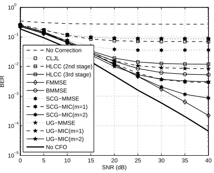
Next, the BER performance of the UG-MMSE-MIC scheme, the SCG-MMSE-MIC scheme and all the discussed schemes is investigated for the OFDMA uplink system with the GCAS
and the BPSK signal in the scenario one. In Fig. 5, the plots show that although the UG-MMSE detector has a similarly inferior performance as the CLJL scheme, with the concatenated IC units, the performance of the UG-MMSE-MIC scheme is greatly improved. At the BER level of 0.007, the performance at the output of the first IC unit (m=1) has nearly 5 dB SNR gain against the BMMSE scheme, nearly 3 dB gain against the HLCC scheme with two IC stages
(m=2), and nearly 1 dB gain against the FMMSE scheme, respectively. Concatenating one more IC unit (m=2) produces more than 5 dB SNR gain at the BER level of 0.002, compared to the UG-MMSE-MIC scheme with one IC unit. On the other hand, the plot also shows that the SCG-MMSE detector has better performance than the CLJL scheme and the HLCC scheme with one IC stage and the performance is further improved when IC units are used. At the
BER level of 0.005, the performance at the output of the first IC unit (m=1) has nearly 3 dB SNR gain against both the BMMSE scheme and the HLCC scheme with two IC stages (m=2). Concatenating one more IC unit (m=2) produces more than 5 dB SNR gain at the BER level of 0.001. The SCG-MMSE-MIC scheme with two IC units has comparable performance with the FMMSE when the SNR level is lower than 30 dB. The FMMSE scheme performs better than
Furthermore, the plot also shows that the UG-MMSE-MIC scheme performs better when the
SNR is lower than around 28 dB but the SCG-MMSE-MIC scheme is better at high SNR level. As we know that the detector is typically operated at low to moderate SNR region for the coded systems, so the UG-MMSE-MIC scheme is more suitable for the coded systems. Note that for the GMMSE detector without IC, the SCG method has better performance than the UG method. In the SCG method, the group is formed according to adjacent subcarriers, where the central
subcarriers are protected from other groups, thus the interference from other groups is much lower than the UG method because in the UG method, each subcarrier in one group possibly is interfered by its neighboring subcarriers, which are located locate in other groups (allocated to different users). However, the situation is different when the IC units are employed. The interference from other groups is cancelled so that the interference coming from the same group
becomes dominant. Since the inter-group interference of the UG method is much smaller than the SCG method, UG-MMSE-MIC becomes better. On the other hand, the performance of the UG-MMSE-MIC also depends on the performance of the previous stage of detection or IC. Thus, with the increase of the SNR, because the residual interference caused by detection errors of the
UG method is larger than that of the SCG method, the UG-MMSE-MIC produces an error floor. That is the reason why there is a crossover between SCG-MMSE-MIC and UG-MMSE-MIC, and why the UG-MMSE-MIC performs better for low SNR and the SCG-MMSE-MIC is better at high SNR.
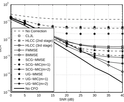
In Fig. 6, we examine the proposed scheme in the scenario two using two parameter settings,
Nsc=4 andNsc=16, denoted as S1 and S2, respectively. Clearly, the proposed scheme withNsc=16
performs better than that with Nsc=4. The complexity of the scheme with Nsc=16 is also much
lower than that of Nsc=4 according to the results in Fig. 3 (b). That is, the flexibility of the
proposed scheme allows us to choose the optimal value for Nsc to achieve the best trade-off
between the performance and complexity.
B. With CFO Estimation Errors
In this part, we consider the case that CFO estimation errors exist. Suppose that CFO estimation has been accomplished by the methods in [14], [15]. The CFO estimation MSE is assumed to be [0.05, 0.003, 0.001, 0.0004, 0.00018, 0.0001, 0.00007, 0.00006, 0.00006] for the corresponding SNRs [0:5:40]. The results are shown in Fig. 8. The results indicate that with reasonable CFO
estimation errors, the impact on the performance of all the algorithms is small.
C. Analytical Performance
To validate the performance analysis, the theoretical performance is evaluated for a simplified demonstration system with N=8 subcarriers,K=4 users, channel order Nh=4,Nsc=4 subcarriers
in each group and G=2 groups, considering extremely high number of C(n, r) operation when
n is large. The theoretical results are shown in Fig. 9 in comparison with simulation results. The simulation results closely match the analytical results and effectively validate the theoretical analysis.
VII. CONCLUSIONS
In this paper, in order to achieve better trade-off between performance and complexity for the OFDMA uplink system, we proposed a grouped minimum mean squared error (G-MMSE) based
multi-stage interference cancellation (MIC) scheme. The first stage of the proposed scheme is a G-MMSE detector, where the signal is detected group by group by a bank of partial MMSE filters. The grouping can be implemented according to either corresponding users or adjacent subcarriers, leading to the UG method and SCG method. By concatenating multiple novel IC units with the G-MMSE detector, the system performance is greatly improved. Since the filters
in the G-MMSE detector can be reused in the subsequent IC units, the computational complexity is greatly reduced according to our complexity analysis. The BEP performance of the proposed scheme is theoretically analysed and validated by simulations. The numerical results show that the proposed G-MMSE-MIC schemes outperforms other existing schemes with considerable low complexity.
REFERENCES
[1] I. Koffman and V. Roman, “Broadband wireless access solutions based on OFDM access in IEEE 802.16”, IEEE Commun.
[2] Z. R. Cao, U. Tureli, and P. Liu, “Optimum subcarrier assignment for ofdma uplink”, ACSSC, Nov. 2003, vol. 1, pp. 708
– 712 Vol.1.
[3] M. Morelli, “Timing and frequency synchronization for the uplink of an OFDMA system”, IEEE Trans. Commun., vol.
52, no. 2, pp. 296-306, Feb. 2004.
[4] Z. R. Cao, U. Tureli, and Y.-D. Yao, “Deterministic multiuser carrier-frequency offset estimation for interleaved ofdma
uplink”, IEEE Trans. Commun., vol. 52, no. 9, pp. 1585-1594, Sept. 2004.
[5] Z. R. Cao, U. Tureli, Y.-D. Yao, and P. Honan, “Frequency synchronization for generalized OFDMA uplink”, in Proc.
IEEE Globecom Nov. 2004, vol. 2, pp. 1071-1075.
[6] K. Y. Kim, Y. N. Han, and S. L. Kim, “Joint subcarrier and power allocation in uplink ofdma systems”, IEEE Commun.
Lett., vol. 9, no. 6, pp. 526 – 528, jun 2005.
[7] M. Pun, M. Morelli, and C. Kuo, “Maximum-likelihood synchronization and channel estimation for OFDMA uplink
transmissions,” IEEE Trans. Commun., vol. 54, no. 4, pp. 726-736, April 2006.
[8] M. Morelli, C.-C.J. Kuo, and M.-O. Pun, “Synchronization techniques for orthogonal frequency division multiple access
(OFDMA): A tutorial review”, Proc. IEEE, vol. 95, no. 7, pp. 1394-1427, July 2007.
[9] D. Marabissi, R. Fantacci, and S. Papini, “Robust multiuser interference cancellation for OFDM systems with frequency
offset”, IEEE Trans. Wireless Commun., vol. 5, no. 11, pp. 3068-3076, Nov. 2006.
[10] D.-F. Huang and K. B. Letaief, “An interference-cancellation scheme for carrier frequency offsets correction in ofdma
systems”, IEEE Trans. Commun., vol. 53, no. 7, pp. 1155 – 1165, July 2005.
[11] S. Manohar, D. Sreedhar, V. Tikiya, and A. Chockalingam, “Cancellation of multiuser interference due to carrier frequency
offsets in uplink ofdma”, IEEE Trans. Wireless Commun., vol. 6, no. 7, pp. 2560-2571, July 2007.
[12] “IEEE Standard for Local and Metropolitan Area Networks, Part 16: Air Interface for Fixed Broadband Wireless Access
Systems”, IEEE Std. 802.16, Oct. 2004.
[13] H. Wang et al., “4G Wireless Video Communications”, Wiley, 2009.
[14] Y. Zeng and A. Leyman, “Pilot-based simplified ML and fast algorithm for frequency offset estimation in OFDMA uplink”,
IEEE Trans. Veh. Technol., vol. 57, no. 3, pp. 1723C1732, May 2008.
[15] P.-F. Sun and L. Zhang, “Low complexity pilot aided frequency synchronization for OFDMA uplink transmission”, IEEE
Trans. Wireless Commun., vol. 8, no. 7, pp. 3758-3769, July 2009.
[16] J. Choi, C. Lee, H. W. Jung, and Y. H. Lee, “Carrier frequency offset compensation for uplink of OFDM-FDMA systems”,
IEEE Commun. Lett., vol. 4, no. 12, pp. 414-416, Dec. 2000.
[17] T. Yucek and H. Arslan, “Carrier frequency offset compensation with successive cancellation in uplink OFDMA systems”,
IEEE Trans. Wireless Commun., vol. 6, no. 10, pp. 3546-3551, Oct. 2007.
[18] Z. R. Cao, U. Tureli, and Y.-D. Yao, “Low-complexity orthogonal spectral signal construction for generalized OFDMA
uplink with frequency synchronization errors”, IEEE Trans. Veh. Tech. , vol. 56, no. 3, pp. 1143-1154, May 2007.
[19] S. Ahmed and L. Zhang, “Low complexity iterative detection for OFDMA uplink with frequency offsets”, IEEE Trans.
Wireless Commun., vol. 8, no. 3, pp. 1199-1205, March 2009.
[20] Van de Beek, J-J., Per Ola Borjesson, M-L. Boucheret, Daniel Landstrom, Julia Martinez Arenas, Per Odling, Christer
Ostberg, Mattias Wahlqvist, and Sarah Kate Wilson, “A time and frequency synchronization scheme for multiuser OFDM
IEEE Journal Sel. Areas Comm., 17.11 (1999): 1900-1914.
[21] A.-L. Johansson, L. K. Rasmussen, “Linear group-wise successive interference cancellation in CDMA”, Proceed. Int. Sym.
[22] L. Dai, S. Sfar and K. B. Letaief, “An Efficient Detector for Combined Space-time Coding and Layered Processing” IEEE
Trans. Commun., v.53, no.9, pp. 1438 - 1442, Sept. 2005.
[23] G. H. Golub and C. F. van Loan, Matrix Computations, Wiley, 2002.
[24] D. R. Brown, M. Motani, V. Veeravalli, H. V. Poor, and C. R. Johnson, Jr., “On the performance of linear parallel
interference cancellation”, IEEE Trans. Inform. Theory, vol. 47, no. 5, pp. 1957-1970, July 2001.
[25] A. N. Barbosa, S. L. Miller, “Adaptive detection of DS/CDMA signals in fading channels”, IEEE Trans. Commun. , v.46,
. . . . . . . . . . .. . . . . . .
Fig. 1. (a) The illustration of entry selection, which can be shared by the UG method with the SCAS and the SCG method
regardless of the CAS, and whereK is the number of users for the UG method andGis the number of groups for the SCG
method. (b) The illustration of entry selection for thek-th user’sΠk for the UG method with GCAS.
S u b c a rr ie r M a p p in g G K/
Y
1Y
) 0 ( /ˆ
K Gs
) 0 ( 1ˆ
s
(1)1
ˆ
s
) 1 ( /ˆ
K Gs
) ( 1ˆ
ms
) ( /ˆ
m G Ks
( ) [image:23.612.75.569.326.471.2]/
ˆ
M G Ks
) ( 1ˆ
Ms
Y
y
y
′
Fig. 2. The diagram of the proposed multi-stage interference cancellation scheme shared by both the UG-MMSE and
SCG-MMSE algorithms, whereK is the number of users for the UG method andGis the number of groups for the SCG method.
1.E+0 1.E+1 1.E+2 1.E+3 1.E+4 1.E+5 1.E+6 1.E+7 1.E+8 Multiplications Additions
1 2 4 8 16 32 64 102 103 104 105 106 107 Nsc M u lt ip li c a ti o n s
1 2 4 8 16 32 64 102 103 104 105 106 107 Nsc A d d it io n s CLJL HLCC (M=2) FMMSE BMMSE SCG-MMSE SCG-MMSE-MIC (M=2)
(a) (b)
Fig. 3. Complexity comparison (a) Complexity comparison for the UG-MMSE-MIC scheme against other existing schemes.
[image:23.612.184.431.538.666.2]TABLE I
THEPSEUDOCODE FOR THEm-THIC UNIT FOR(A)THEUG-MMSE-MICSCHEME(B)THESCG-MMSE-MICSCHEME..
(a)
1: fork= 1toK do
2: Initiatings(m)=0N, where0N is the zeros column vector of orderN.
3: Mapping(ˆs(m−1)
1 , ...,ˆs
(m−1)
k−1 ,ˆs
(m−1)
k+1 , ...,ˆs
(m−1)
K )tos
(m);
4: Y(m)=Y −Πs(m);
5: Y(m)
k =Y
(m)
(Ik);
6: z(m)
k =W
H kY
(m)
k ; 7: ˆs(m)
k = ˆs
(m−1)
k = Restore(zk); 8: end for
(b)
1: forg= 1 toGdo
2: Initiatings(m)=0N, where0N is the zeros column vector of orderN.
3: Mapping(ˆs(1m−1), ...,ˆs(m−1)
g−1 ,ˆs
(m−1)
g+1 , ...,ˆs
(m−1)
G )tos
(m)
;
4: Y(m)=Y −Πs(
m);
5: Y(gm)=Y(m)(Ig);
6: z(gm)=WHgY(gm);
7: sˆ(gm)= ˆsg(m−1)= Restore(zk);
8: end for
TABLE II
COMPUTATIONAL COMPLEXITY OF ALGORITHMS.
Algorithm
Number of operations per block
Multiplications Additions
CLJL [16] KN2
c KN
2
c−KNc
HLCC [10] M KN2
+ (K+ 2M K)N2
c−2M KNcN M KN
2
+ (K+ 2M K)N2
c−(K+M K)Nc
FMMSE 3N3+N2+N 2N3−2N2+N
BMMSE [18] 5N τ2
+ 9N τ+ 3N 5N τ2
+ 8N τ+ 2N
UG-MMSE 3KN3
c+KN
2
c+Nc 2KN
3
c−2KN
2
c+KNc
UG IC Unit KN2
−2KN Nc+ 2KN
2
c KN
2
−KN Nc+KN
2
c−KNc
UG-MMSE-MIC M KN2−2M KN Nc+ 3KN
3
c+ (K+ 2M K)N
2
c M KN
2
−M KN Nc+ 2KN
3
c+ (M K−2K)N
2
c+ (K−M K)Nc
SCG-MMSE 3GNsc3 +GNsc2 +Nsc, 2GN
3
sc−2GN
2
sc+GNsc,
SCG IC Unit GN2−2GN Nsc+ 2GN
2
sc GN
2
−GN Nsc+GN
2
sc−GNsc
SCG-MMSE-MIC M GN2
−2M GN Nsc+ 3GN
3
sc+ (G+ 2M G)N
2
sc M GN
2
−M GN Nsc+ 2GN
3
sc+ (M G−2G)N
2
0 5 10 15 20 25 30 35 10−5
10−4 10−3 10−2 10−1 100
SNR (dB)
BER
No Correction CLJL HLCC (m=1) HLCC (m=2) BMMSE (τ=30) FMMSE GMMSE MIC−GMMSE (m=1) MIC−GMMSE (m=2) No CFO
Fig. 4. BER against SNR performance comparison of the UG-MMSE-MIC scheme and other existing schemes using the SCAS
and the BPSK signal.
0 5 10 15 20 25 30 35 40 10−5
10−4 10−3 10−2 10−1 100
SNR (dB)
BER
[image:25.612.197.409.119.291.2]No Correction CLJL HLCC (2nd stage) HLCC (3rd stage) FMMSE BMMSE SCG−MMSE SCG−MIC(m=1) SCG−MIC(m=2) UG−MMSE UG−MIC(m=1) UG−MIC(m=2) No CFO
Fig. 5. BER against SNR performance comparison of the UG-MMSE-MIC scheme, the SCG-MMSE-MIC scheme and other
[image:25.612.196.411.444.617.2]0 5 10 15 20 25 30 35 10−4
10−3 10−2 10−1 100
SNR (dB)
BER
[image:26.612.196.409.115.288.2]No Correction CLJL HLCC (m=1) HLCC (m=2) BMMSE (τ=30) FMMSE SCG−MMSE (S1) MIC (m=1,S1) MIC (m=2, S1) SCG−MMSE (S2) MIC (m=1,S2) MIC (m=2,S2) No CFO
Fig. 6. BER against SNR performance comparison of the SCG-MMSE-MIC scheme and other existing schemes for the GCAS
and the BPSK signal in the second scenario, withk= 8, Nc= 16. S1 stands for the first setting withNsc= 4; S2 stands for
the second setting withNsc= 16.
0 5 10 15 20 25 30 35 40 10−5
10−4 10−3 10−2 10−1 100
SNR (dB)
BER
No Correction CLJL HLCC (2nd stage) HLCC (3rd stage) FMMSE BMMSE SCG−MMSE SCG−MIC(m=1) SCG−MIC(m=2) UG−MMSE UG−MIC(m=1) UG−MIC(m=2) No CFO
Fig. 7. BER against SNR performance comparison of the UG-MMSE-MIC scheme, the SCG-MMSE-MIC scheme and other
[image:26.612.195.411.448.623.2]0 5 10 15 20 25 30 35 40 10−5
10−4 10−3 10−2 10−1 100
SNR (dB)
BER
[image:27.612.197.408.117.291.2]No Correction CLJL HLCC (2nd stage) HLCC (3rd stage) FMMSE BMMSE SCG−MMSE SCG−MIC(m=1) SCG−MIC(m=2) UG−MMSE UG−MIC(m=1) UG−MIC(m=2) No CFO
Fig. 8. BER against SNR performance comparison of the UG-MMSE-MIC scheme, the SCG-MMSE-MIC scheme and other
existing schemes using the GCAS and the BPSK signal, considering CFO estimation errors.
0 5 10 15 20 25 30 35 10−4
10−3 10−2 10−1 100
SNR (dB)
BER
Theoretical SCG−MMSE Theoretical SCG−MMSE−MIC (m=1) Theoretical SCG−MMSE−MIC (m=2) Theoretical Perfect IC
Simulation SCG−MMSE Simulation SCG−MMSE−MIC (m=1) Simulation SCG−MMSE−MIC (m=2) Simulation Perfect IC
Fig. 9. BER against SNR performance comparison between the theoretical results and the simulation results in a demonstration
[image:27.612.197.411.445.618.2]