This is a repository copy of
FENet: An SDN-based scheme for virtual network
management
.
White Rose Research Online URL for this paper:
http://eprints.whiterose.ac.uk/97050/
Version: Accepted Version
Proceedings Paper:
Liu, K, Wo, T, Cui, L et al. (2 more authors) (2014) FENet: An SDN-based scheme for
virtual network management. In: 20th IEEE International Conference on Parallel and
Distributed Systems. ICPADS, 16-19 Dec 2014, Hsinchu, Taiwan. IEEE , pp. 249-256.
ISBN 978-1-4799-7615-7
https://doi.org/10.1109/PADSW.2014.7097815
[email protected] https://eprints.whiterose.ac.uk/
Reuse
Unless indicated otherwise, fulltext items are protected by copyright with all rights reserved. The copyright exception in section 29 of the Copyright, Designs and Patents Act 1988 allows the making of a single copy solely for the purpose of non-commercial research or private study within the limits of fair dealing. The publisher or other rights-holder may allow further reproduction and re-use of this version - refer to the White Rose Research Online record for this item. Where records identify the publisher as the copyright holder, users can verify any specific terms of use on the publisher’s website.
Takedown
If you consider content in White Rose Research Online to be in breach of UK law, please notify us by
FENet: An SDN-Based Scheme for Virtual
Network Management
Kun Liu
1, Tianyu Wo
1, Lei Cui
1, Bin Shi
1, Jie Xu
1,2{liukun, woty, cuilei, shibin}@act.buaa.edu.cn, [email protected]
1State Key Laboratory of Software Development Environment
Beihang University Beijing, China
2School of Computing
University of Leeds Leeds, UK
Abstract—Virtual networking is vital to efficient resource management in Clouds, and it is in fact one of the main services provided by many Cloud Computing platforms. Virtual network management needs to meet specific requirements, including tenant isolation and adaption to
virtual machines’ lifecycle. Most of the existing schemes for
virtual network management are based on the use of overlay networks in order to achieve a desirable degree of flexibility. However, these schemes suffer from a common limit, i.e. relatively high performance penalty due to a complicated forwarding process. We address this performance concern by developing a new management scheme, FENet, which makes use of Software-Defined Networks (SDN) to create virtual networks and manage them via the SDN controller programs. We present the design of an SDN controller, with the definition of flow entry rules based on the OpenFlow protocol and the specification of a routing algorithm. The results from our experimental evaluation show that our SDN-based prototype can control virtual network interconnections and tenant isolation appropriately. FENet achieves about 30% better network performance than the management scheme based on OpenVPN and lower latency in comparison with the traditional bridging scheme.
Keywords—Cloud Computing; OpenFlow; SDN; tenant isolation; virtual networks;
I. INTRODUCTION
Cloud Computing platforms provide services such as computing, storage, networking and security. As more and more distributed applications run on the Cloud Computing virtualization platforms, virtual networks become very important. The management of virtual networks differs from the physical networks in some aspects. Firstly, several virtual machines (VM) on the same host share the physical hardware including network interface cards (NIC), thus the management scheme needs to consider either transferring the virtual network packets via physical networks directly, or encapsulating them in the hosts’ packets to forward. Secondly, tenant isolation should be supported as it is important to ensure security and
eliminate impacts among tenants. Thirdly, The
management scheme should flexibly adapt to the virtual network topology’s changes that result from the VM operations like starting, migrating and deleting.
Nowadays, the common management schemes of virtual networks can be divided into two types. One is based on traditional bridging (taken by OpenStack [1]), which binds the VMs’ NICs with the physical NICs on a
virtual bridge, and transfers the virtual network packets via the physical NICs. Though this transfer method achieves good network performance, the virtual network management lacks of flexibility, for example, lots of configuration work is needed and tenant isolation is constrained to limited number of tenants. The other type is based on overlay networks [2, 3], which encapsulates the virtual network packets into the hosts’ packets, and forwards them by tunneling technique. This type of scheme achieves flexible virtual network management, however, the use of overlay networks leads to network performance loss because of the complicated forwarding process. It is hard to balance the trade-off between flexible management and network performance by traditional methods.
Over the past few years, Software-Defined Networks (SDN) [4] has become a research hot spot in the area of networking. SDN proposes separating the control plane and data plane of the switches, and concentrating the control planes into an uniform controller. The controller manages the whole network and instructs the switches to handle network packets. By leveraging the idea of SDN, it is possible to achieve flexible control and good network performance, because management logic in the devices can be accomplished conveniently. SDN has been used to develop improved solutions in areas like data center networks [5] and traffic engineering [6], however, research that aims at virtual network management is incomplete. For examples, [7] proposes an SDN-based method for tenant isolation, it enables communications among VMs only while Internet access is ignored. Besides, it does not consider how to handle broadcast packets.
The remainder of this paper is organized as follows: Section II introduces the related work; Section III describes the details of design and implementation; Section IV presents the evaluation of the prototype with functional and performance experiments; Section V concludes the paper and describes the future work.
II. RELATED WORK
A.Management schemes based on traditional bridging
Management schemes based on traditional bridging leverage virtual Ethernet bridge (Linux Bridge, Open vSwitch [9]) to transfer the VMs’ network packets via the host’s NICs, then the packets are delivered to the physical networks. 802.1Q protocol is taken to achieve tenant isolation. Tenants are allocated with different VLAN identification numbers, and the network packets sent from VMs belonging to a tenant are tagged with an unique VLAN identification number, thus switches isolates the packets according to the VLAN tags. However, the VLAN tag in the Ethernet packets is only 12 bits long, which means the isolation units are no more than 4096. Methods like private VLAN [10] and VXLAN [11] are proposed to address this issue. Private VLAN configures the switches with two-level VLAN strategy and maintains a VLANs’ mapping table, but its effect is not good as the packets forwarding become more complicated and the mapping table cannot be large enough. VXLAN is a kind of overlay networks actually. Schemes based on traditional bridging are not flexible enough as physical switches need lots of configuration like VLAN strategy, gateway and routing rules. Besides, VM migration is restricted within a layer-2 network in order to keep the network configuration of VMs unchanged.
B.Management schemes based on overlay networks
Overlay networks are logical networks that built upon physical networks. Management schemes based on overlay networks encapsulate the virtual network packets into the hosts’ packets, and the encapsulation modules take charge of the management issues, such as network routing, tenant isolation and traffic measurement. The related projects includes VNET [2], IPOP [3] and OpenVPN [12]. In VNET, the virtual network packets are encapsulated and sent to a host acting as proxy. The proxy host will forward the packets to the host where the destination VM locates. IPOP creates a virtual device and binds it with the VMs’ NICs, thus the hosts’ programs could capture the virtual network packets by executing traditional read/write operations to the virtual device. OpenVPN is open-source implementation of VPN, which transfers network packets between different local area networks by IP tunneling. Usually, tunneling is used to extend the overlay networks across layer-3 networks. Nowadays, many Cloud Computing solutions take this type of scheme, such as VXLAN in VMware ESX, NVGRE [13] in Windows Azure and Amazon VPC [14].
In these schemes, tenant isolation is indicated by tunneling identification numbers, which is plenty enough to meet the demand of large amount of isolation units. Besides, these schemes have fewer constraints to VM migration because the network packets are encapsulated. However, the use of overlay networks suffers from higher
performance loss in comparison with schemes based on bridging, because the virtual network packets will be forwarded to the programs in the hosts firstly, and then sent out as data contents in the physical packets. So the total process takes twice copy operations between user space and kernel space. In addition, the routing of virtual network packets is handled by virtual routers on the hosts rather than physical network devices. The common virtual routers are acted by VMs with several NICs, which are less efficient compared with physical routers.
C.Software-defined networks
Software-defined networks [4] could be used to address issues like the network management becomes too tough as the network scales up. The advantage of SDN is that developers could manage the networks much more flexibly and conveniently by designing the controller programs, which maintain the network topology and control the networks including routing, configuration and flow control. OpenFlow [8] is now a famous protocol in SDN that enables the communication between the controller and network devices. The main contents of OpenFlow protocol include the working process of OpenFlow switch, the structure of flow tables and message types between the controller and OpenFlow switches.
The research of SDN is focused on the controller design and improved methods of networking areas. Researchers pay high attentions to the SDN controller’s performance [15, 16] as well as reliability [17], and advanced controllers likes Onix [18] are proposed to further improve the SDN network performance. Besides, SDN is applied to areas such as data center networks [5], QoS [19] and network virtualization [20].
Nicira Network Virtualization Platform (NVP) [21] proposes solutions aiming at virtual network management, it combines SDN and IP tunneling to achieve virtual network interconnections and isolation. However, IP tunneling makes the transfer process more complicated, which may result in performance loss. [7] proposes a method of tenant isolation based on SDN, but it only works when the hosts are in a layer-2 network, because it replaces the packets’ destination MAC address with the host’s MAC address while the destination IP address is still the VM’s, so the packets cannot be routed across physical layer-2 networks. Besides, this method does not provide Internet access for the VMs. The OpenFlow protocol is flexible and it is possible to realize more management logic by flow entry rules.
III. DESIGNS AND IMPLEMENTATION
should design special flow entry rules to provide features like routing and tenant isolation. Besides, to adjust the flow entry rules accurately, the management scheme also needs to define interactive interfaces between the SDN controller and virtualization platforms. FENet is a kind of management scheme that designed according to above ideas.
The virtual network structure in FENet is as Fig.1 shows. Hosts are connected to virtual networks and the management network via two NICs, each host runs Open vSwitch (also supports OpenFlow protocol) to connect VMs. All the physical OpenFlow switches are connected with the controller via the management network. Besides, hosts are configured with NAT strategy for VMs’ Internet access, and Open vSwitch acts as gateway for VMs.
Fig.1. The structure of SDN-based virtual networks
The SDN controller maintains the global view of virtual networks. Once VM operations happen, the OpenFlow switches will send messages to the controller, which will handle the messages according to management
strategies. The general management strategies of virtual networks are as follows:
Routing: VMs belonging to the same tenant could
communicates with each other, no matter they are in the same subnet or not;
Tenant isolation: VMs that belong to different tenants are isolated;
Broadcast handling: ARP/DHCP requests from
VMs are handled by the controller directly rather than broadcasting in the networks;
Internet access: All the VMs can access the
Internet via their gateways;
A.OpenFlow flow entry rules
OpenFlow switches handle the network packets according to the inside flow tables. To design reasonable and accurate flow entry rules, we need to classify and analyze the virtual network packets first. Network packets from VMs include data-link layer broadcast packets, IP layer broadcast packets, IP layer unicast packets, multicast packets and so on. At present, FENet has supported ARP broadcast packets, DHCP broadcast packets and regular IP unicast packets. Other network packets will be considered later. For example, multicast packets can be supported by maintaining multicast groups in the SDN controller. The classification of packets sent from/to VMs are shown in Table 1 and Table 2.
Open vSwitch acts as access switch for the VMs, thus the packets sent from VMs are firstly handled by Open vSwitch. For ARP requests, Open vSwitch permits them to transfer if the request’s source VM belongs to the same tenant with the target VM/gateway, otherwise the request packets are discarded. After passing the validation, the ARP requests will be forwarded to the controller. As the controller stores the VMs’ information, it can easily find out the requested destination MAC address and send back ARP reply packets to the Open vSwitch. By this way, ARP broadcast packets will not be transferred in virtual networks, which avoids network bandwidth occupied by large amount of broadcast packets as the network scales.
TABLE 1. PACKETS SENT FROM VM
Packet Type Destination (address) Flag Permitted Handling
ARP Request Broadcast address Out_1 Yes within the same tenant Forward to the controller No other cases Discard
DHCP Request Broadcast address Out_2 Yes Forward to the controller
IP
VM (belongs to same tenant & same subnet) Out_3 Yes Forward to the VM VM (belongs to same tenant & different subnet) Out_4 Yes Route & forward to the VM Gateway (belongs to same tenant) Out_5 Yes Forward to the gateway Other internal IP addresses (Reserved IP)
10.0.0.0/8 | 172.16.0.0/16 |192.168.0.0/24 Out_6 No Discard
Internet Out_7 Yes Forward to the gateway
Others (such as multicast address) Out_8 No (at present) Discard
TABLE 2. PACKETS SENT TO VM
Packet Type Source (address) Flag Permitted Handling
ARP Reply The controller In_1 Yes Forward to the VM or gateway
DHCP Reply The controller In_2 Yes Forward to the VM
IP
VM belongs to the same tenant In_3 Yes Forward to the VM
VM belongs to different tenants In_4 No Discard
Gateway In_5 Yes Forward to the VM
Internet In_6 Yes Forward to the VM
Others(such as multicast address) In_7 No (at present) Discard VM-7
OpenFlow switch
Management network Virtual networks
Open vSwitch eth0
eth1 SDN Controller
VM-1 VM-2
Open vSwitch eth0
eth1
VM-3 VM-4
M
Management network
Host-1 Host-2
M Management port
OpenFlow switch OpenFlow switch
M M
Open vSwitch eth0
eth1 Host-3
Besides, the packet validation filters spiteful ARP request packets, thus the controller can efficiently respond to the legal requests. The packet validation in Open vSwitch is applied to IP packets and DHCP request packets as well.
FENet takes OpenFlow version 1.3.0 specification. Switches supporting OpenFlow v1.3 handle the packets by several steps in a pipeline, and each step is instructed by a flow table. A special variable called metadata is transferred between adjacent steps to carry additional information. The flow table is a set of flow entries, and a flow entry is one record that consists of several fields
including Match Fields, Priority, Counters and
Instructions. The Match Fields is a set of several field types that refer to the outermost occurrence of the fields in the packet headers, for examples, Field eth_dst refers to the destination MAC address in the Ethernet packet headers. If a packet matches one flow entry’s Match Fields, the corresponding Counters updates and the switch handles the packet as the Instructions indicates.
The OpenFlow flow entry rules in physical switches are different from Open vSwitch’s, because Open vSwitch acts as access switch and plays an important role in validating the incoming packets, while the physical switches just forward the packets to the right destination. we select several match fields according to the OpenFlow protocol specifications: eth_src identifies the source MAC address, eth_dst identifies the destination MAC address, ip_dst identifies the source IP address, arp_tpa identifies the requested IP address in ARP request packets.
Assume that VMa (IP address is ip, MAC address is
mac, gateway is gw and belongs to tenant T1) is connected
to the Open vSwitch S on port P, the flow entry installation for virtual networks is as follows:
1) To handle the packets sent out from VMa, install
one flow entry to the flow-table 0 (used in the first step of the process pipeline) in all switches, the Match Fields is ‘eth_src= mac’, the Priority is 2 and the Instructions is ‘set metadata= T1 and
go to flow table 1 (used in the second step of the pipeline)’.
2) To handle the packets sent to VMa, install two
flow entries in Open vSwitch S: one to flow-table 0 with the Match Fields is ‘eth_src=mac’, the Priority is 1 and the Instructions is ‘Forward packets to port P’; the other one to flow-table 1
with the Match Fields is ‘eth_src=mac,
metadata=T1’, the Priority is 4 and the
Instructions is ‘Forward packets to port P’; 3) To handle the packets sent to VMa in other
switches except from S, the controller computes each switch Si’s routing path to VMa and gets the
next hop port number Pi, after that it installs one
flow entry to flow-table 1 in switch Si, the Match
Fields is ‘eth_src=mac, metadata=T1’, the
Priority is 1 and the Instructions is ‘Forword packets to port Pi’;
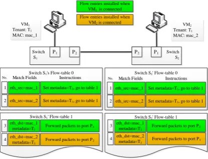
Combining the rule 1 to 3 together enables VMs to communicate with the ones belonging to the same tenant.
For example, as Fig.2 shows, when VM1 sends packets to
VM2, the packets firstly match No.1 flow entry of switch
S1’s table 0, and then match No.3 flow entry in
flow-table 1, so the packets are sent to switch S2. In switch S2,
the packets match No.1 flow entry of flow-table 0 firstly and then match No.4 flow entry of flow-table1, and eventually get to VM2.
Switch S2' Flow-table 0 Switch S1's Flow-table 0
eth_src=mac_1 Set metadata=T1, go to table 1
Switch S1' Flow-table 1
Flow entries installed when VM1 is connected
eth_dst=mac_2 metadata=T1
Forward packets to port P2
Flow entries installed when VM2 is connected
eth_src=mac_1 Set metadata=T1, go to table 1
Switch S2' Flow-table 1
eth_dst=mac_1 metadata=T1
Forward packets to port P2
eth_dst=mac_2
metadata=T1 Forward packets to port P1
eth_dst=mac_1 metadata=T1
Forward packets to port P1
Switch S1
Switch S2
P1 P2 P2 P1
VM1
Tenant: T1
MAC: mac_1
VM2
Tenant: T1
MAC: mac_2
1
3
4
1
3
4
Match Fields
Match Fields InstructionsInstructions No.
No. No.No. Match FieldsMatch Fields InstructionsInstructions
eth_src=mac_2 Set metadata=T1, go to table 1 2
eth_src=mac_2 Set metadata=T1, go to table 1
[image:5.595.320.528.151.309.2]2
Fig.2. An example of communication between VMs
4) Install default flow entry (Priority=1) for ARP request packets with Instructions is ‘Drop’. And for ARP request packets that request for VMa’s
MAC address, install a flow entry to flow table-1 in each switch, the Match Fields is ‘Packet type is ARP request, arp_tpa=ip and metadata=T1’,
the Priority is 2 and the Instructions is ‘Forward packets to the controller’. The controller will handle the requests and send the ARP reply packets back to the access switch. The flow entry rule for VMa’s DHCP requests is similar.
5) To handle the packets sent from VMa to Internet,
the controller computes the routing path for VMa
to access its gateway, and install a flow entry to switches along the path. The flow entry’s Match
Fields is ‘metadata=T1, eth_src=mac and
eth_dst=gw’, the Priority is 1 and the
Instructions is ‘Forward to the next hop port’. 6) When VMs that locate in other different subnets
send packets to VMa, the packets’ destionation IP
address is ip but destination MAC address is their gateways’ address, so the controller install a flow entry rewirting the destination’s MAC address to mac into the Open vSwitch. The flow entry’s Match Fields is ‘metadata=T1, ip_dst=ip and
eth_dst=gw’, the Priority is 3 and the
Instructions is ‘Write eth_dst=mac and forward the packets to the next hop port’. This method achieves efficient routing process.
7) To achieve tenant isolation, we appoint all the VMs are configured with internal IP addresses (marked as Reserved IP) [22]. A default flow entry is installed to flow table-1 in each switch, the Match Fields is ‘ip_dst=Reserved IP and
eth_dst=gw’, the Priority is 2 and the
To conclude above rules, there are two steps in the process pipeline of Open vSwitch, and flow entries in Open vSwitch will cover all the types of network packets listed in Table 1 and Table 2. Assume that the number of VMs is N, then the total number of flow entries in flow
table-0 is about 2N thus FENet supports more than
32,000 VMs under the size limitation of flow table (in our environment, 65535), and the tenant isolation units can be as many as the number of VMs.
B.Routing algorithm in FENet
When a new VM is connected to the network, the controller computes the routing path for every switch to access the VM. The common method is the shortest path algorithm that just takes the hop counts between switches into consideration. Since the controller stores the network topology, computing the routing path only once is very efficient for the controller to respond to the flow entry installation requests. However, the location of VMs usually depends on the loads of the hosts, such as CPU and memory, which means hop count-based routing may lead to low network utilization and load unbalanced. To address this problem, we choose to execute the routing algorithm each time a new VM is connected, and the routing algorithm will do its best to allocate loads evenly within the entire network. Prediction of the network traffic is a tough issue, so we identify a network link’s load by the count of VMs that will send packets through it.
In FENet, we design several dictionary variables for Switch objects. The variable nextHop refers to the links established between switches, variable nextHopCount refers to the count of VMs that send packets through network links in nextHop, variable local_vm refers to the VMs directly connected to the switch, and variable remote_vm refers to the VMs that send packets through the switch. The data structures of these variables are shown in Table 3.
TABLE 3. DATA STRUCTURES OF DICTIONARY VARIABLES
Attributes Format
nextHop {‘port_num’ : ‘switch_addr’}
nextHopCount {‘port_num’ : ‘count’}
local_vm { ‘tenant_id’ : {‘vm_mac’: ‘port_num’} }
remote_vm { ‘tenant _id’ : {‘vm_mac’: ‘port_num’} }
FENet executes the routing algorithm by two stages. The first stage is updating the load of each link because the new VM may have access to VMs belonging to the same tenant. Assume that all the Switch objects are stored in array switch, a new VMa (belongs to tenant t1, MAC
address is mac) is connected to switch SA (stored in
switch[i]) at port P0. Algorithm 1 describes the procedure
of the first stage:
Algorithm 1 Updating the load of links when a new VM added
1. switch[i].local_vm[t1][mac] = P0
2. for mac, port in switch[i].remote_vm[t1].items( ):
3. sw = switch[i]
4. while sw.remote_vm[t1].has_key(mac) :
5. port_num = remote_vm[t1][mac]
6. // update the load of network link from one vertex: 7. sw.nextHopCount[port_num] += 1
8. sw = sw.switch[nextHop[port_num]] 9. // update the other vertex’s nextHopCount 10. end while
11. end for
The second stage of the algorithm selects the routing path for every switch to access VMa , the selection process
is based on greedy strategy. We define the maximum load of all the network links in one path as the path’s load. Switches that to be routed are marked as unvisited, and the algorithm maintains several variables for each unvisited switch Si , including variable Popt(i) that stores the optimal
path for Si to VMa , load_count(i) that stores the load of
Popt(i). Besides, the load of link between Si and its
previous switch along Popt(i) is stored in previous_count(i),
and the hop count of Popt(i) is stored in distance(i), all
these three variables related to Popt(i) are the smaller the
better. Each round the algorithm selects the optimal Popt
from Popt(i) at a priority order of load_count >
previous_count > distance, and marks the corresponding switch Si as visited Snew , which means the routing path for
Snew to access VMa is found. If Snew connects VMs that
belong to the same tenant as VMa , the algorithm needs to
update the previous_count of the switches on Popt and the
load_count of other affected Popt(i). The pseudo codes of
updating operations are as Algorithm 2 shows.
Algorithm 2 Updating affected load_count and previous_count
1. vm_count = Snew.local_vm[t1].count()
2. if vm_count > 0: 3. sw = Snew
4. // update the previous_count of switches till SA
5. // variable previous stores the previous switches on the path to SA:
6. while not sw == SA:
7. previous_count[sw] += vm_count 8. root_sw = sw
9. sw = previous[sw] 10. end while
11. // update the affected switches’ load_count 12. queue.push(root_sw)
13. while not queue.empty(): 14. sw = queue.pop()
15. load_count[sw] += vm_count
16. // AFFECTED_SET is the set of switches whose Popt(i) contains
17. // sw and load_count(i) < load_count[sw] : 18. for switch in AFFECTED_SET: 19. queue.push(switch) 20. end for
21. end while 22. end if
At the end of each selection round, the algorithm traverses Snew’s unvisited neighbor switches to check
whether there is any improvement of Popt(i) through Snew.
Assume that the number of switches is N, then the time complexity of the total routing algorithm is O (N3).
C.VM operations handling processes
The SDN controller maintains the virtual network topology, including the information of all the VMs and switches. To ensure the consistency of relations between VMs’ status and the switches’ flow entry rules, FENet takes a series of VM operations handling processes between the SDN controller and virtualization platforms. By this way, FENet accurately adjusts the flow entry rules and achieves flexible management. Usually virtualization platforms provide a web interface (marked as portal) for the users to access, thus we use portal to represent virtualization platforms in the following description.
1) VM deploying
The portal sends the new VM’s information (network
that the controller inserts a record of this VM into the database, and sets the VM’s status to deployed.
2) VM starting
When the VM starts, its access switch will report to the controller about an OpenFlow message that a port turns to UP status, and this message contains the access
device’s MAC address. The controller queries the
database to get the VM record and checks the status of the VM. If the status is deployed or migrated, then the controller will install new flow entries to the related switches.
3) VM migrating
The portal sends the migrating operation details to the controller, including information of the migrating VM and the target host. Then the controller updates the migrating VMs’ status to migrated and sets its access_switch to the target switch. Once the VM starts on the target host, the next handling process is similar with 2).
4) VM stopping
The portal sends the stopping operation details to the controller, and the controller updates the target VM’s status to stopped.
5) VM deleting
The portal sends the deleting operation details to the controller, and then the controller updates the target VM’s status to deleted. When the target VM shuts down, the controller will receive an OpenFlow message from the access switch that a port turns to DOWN status, and it queries the database to get the VM record that matches the MAC address contained in the OpenFlow message. If the VM’s status is deleted, then the controller instructs all the switches to delete flow entries related to the deleted VM, and updates the load of network links.
IV. EXPERIMENTAL EVALUATIONS
The prototype of FENet is developed upon RYU [23], which provides OpenFlow interfaces for developing SDN controller programs. We conduct functional experiments to validate the effectiveness of the prototype. Besides, performance experiments are conducted to evaluate the prototype, including the virtual network performance and the scalability of virtual networks.
A.Virtual network interconnections and isolation
We build a virtual network as Fig. 4 shows. 2 hosts are connected to an H3C S5820 OpenFlow switch, and each host runs 4 VMs. The VMs are tagged with several tenants’ ID, and some of them are configured with IP addresses belonging to different subnets. Various experiment conditions makes accurate validation of virtual network interconnections and isolation.
Firstly, we take ping tests among the 8 VMs. The partial results are shown in Table 4. As we expected, the VMs belonging to the same tenant could communicate each other, no matter their IP addresses are in the same subnet or not. And the VMs belonging to different tenants are isolated. The results verify that virtual network interconnections and isolation are controlled accurately. Secondly, we test the VMs to access the Internet. The virtual network has 5 subnets, but there are only two true
Host-A
H3C OpenFlow Switch
hostname: VM1
owner: T1
IP: 10.0.1.2/24 gateway: 10.0.1.1
Open vSwitch IP: 10.0.1.1/24
hostname:VM2
owner: T1 IP: 10.0.1.4/24 gateway: 10.0.1.1
hostname: VM5
owner: T2 IP:10.1.1.2/24 gateway: 10.1.1.1
hostname: VM6
owner: T3 IP: 10.2.1.2/24 gateway: 10.2.1.1
Host-B hostname: VM
8
owner: T3 IP: 10.2.2.2/24 gateway: 10.2.2.1 Open vSwitch
IP: 10.1.1.1/24
hostname: VM3
owner: T1 IP: 10.0.1.3/24 gateway: 10.0.1.1
hostname: VM4
owner: T1 IP: 10.0.2.3/24 gateway: 10.0.2.1
hostname: VM7
owner: T2 IP: 10.1.1.3/24 gateway: 10.1.1.1
Fig.4. Network topology of functional experiments
gateway devices, thus VMs belonging to tenant T1 and
tenant T3 are mapped to gateway on host-A, while those
belonging to tenant T2 are mapped to gateway on host-B.
The results show all the VMs could communicate with public IP addresses. This test verifies that different subnets could share a gateway for accessing the Internet. That’s valuable as in production environment the number of virtual subnets increases dynamically while the hosts’ is usually fixed.
TABLE 4. PING TESTS RESULTS
Use Case
Conditions
Expected Result
Test Result
Same tenant
Within subnet
Same Host
VM1VM2 Yes Yes Yes enabled enabled
VM1VM3 Yes Yes No enabled enabled
VM3VM4 Yes No Yes enabled enabled
VM2VM4 Yes No No enabled enabled
VM2VM5 No No Yes rejected rejected
VM6VM7 No No No rejected rejected
B.Virtual network performance
We realize the control of a 4 VMs’ virtual network by 3 types of schemes respectively, including scheme based on OpenVPN, scheme based on traditional bridging and FENet. All the three schemes use Open vSwitch-2.0.0 as the VMs’ access switch. VM1 and VM2 run on the host-A,
and their IP addresses are configured in a same subnet. VM3 and VM4 run the host-B, VM3 is in the same subnet
with VM1/VM2 while VM4 is in another subnet. These 4
VMs belong to the same tenant, thus they are able to communicate with each other.
We measure the network performance between VMs by Iperf and ping. The results are shown in Fig. 5 and Fig. 6. We use openvpn to identify the OpenVPN scheme, and use bridging to identify the traditional bridging scheme.
VM1 and VM2 communicate with each other via a
layer-2 network because they are connected with the same Open vSwitch and their IP addresses are configured in the same subnet, so the packet forwarding process of these three schemes are similar, the result shows the bandwidth of communication between VM1 and VM2 are about
400Mbits/s. Though VM3 and VM4 run on the same host,
they are configured into different subnets, thus the packets forwarding between them needs layer-3 routing. bridging leverages physical layer-3 switches to accomplish routing, the packets are sent out from host-B firstly and then sent back to host-B after routing. FENet makes use of packet headers rewriting to accomplish routing and the packets are forwarded within host-B. openvpn runs a VM as virtual router. The results show FENet and bridging
provide better bandwidth of communication between VM3
and VM4 than openvpn. FENet improves the bandwidth
further by a special routing method.
Fig.6. Latency of communication between VMs
When VMs that locate different hosts communicate with each other, the network performance in FENet is about 30% higher than openvpn. Because in openvpn, the packets are encapsulated and sent to the VPN server for transferring. Besides, the routing process handled by virtual router also pays a cost of performance loss.
Packets transfer process of FENet is essentially based on bridging, so the bandwidth performance of FENet and bridging are similar. However, the results show FENet achieves lower latency. On the one hand, bridging takes VLAN field as the tenant isolation identification tag, thus the operations of adding/removing VLAN tags are additional in compared with FENet, on the other hand, FENet accomplishes routing efficiently by packet headers rewriting.
C.The scalability of virtual netwoks
As we described in sector II, the flow entry rules in FENet support more than 32,000 VMs, and FENet is faced with challenges of virtual networks’ scalability in two aspects, one is responding to the ARP requests, and the other is responding to VM startup and installing flow entries to the switches. We run Cbench [24] to measure the responding ability of the controller. The controller application is running on a host that has 8 cores of Intel(R) Core(TM) i7 CPU 860 @2.80GHz and 8 GB memory.
Firstly, we measure the controller’s throughput of ARP replies when different amounts of switches are connected to the controller, we assume that each switch
has a fixed number of hosts of 100, which is above the common case of today’s commercial products. The results are shown in Fig.7. As the number of switches increases, the throughput of the controller keeps improving till an upper bound is reached. Finally, the throughput holds steady at more than 18,000 responses per seconds, because the CPU usage reaches 100%.
Fig.7. The throughput of controller with different number of switches
Besides, we measure the elapsed time of OpenFlow flow entry installation when a VM is connected to virtual networks of different scale. The virtual network scale is determined by the amount of physical switches, each physical switch is connected with 20 Open vSwitch. When the controller manages a virtual network of 64 physical switches, it will install flow entries for 1280 switches (including software based Open vSwitch), the elapsed time of flow entry installation for one VM is 1.185 seconds, and the results of other cases are shown in Fig.8. As RYU is single-threaded the controller has to take serial processing for flow entry installation when plenty of VMs concurrently start. In a virtual network of 4 physical switches, when 1000 VMs start at the same time, the total elapsed time of flow entry installation is about 81 seconds.
Fig.8. Elapsed time of flow entry installation for one VM
D.Network utilization of routing algorithm
In this test we run twelve VMs on six hosts. These VMs are allocated to different tenants, VM1,2,3 belong to
tenant-1, VM4,5,6,9,10 belong to tenant-2 and VM7,8,11,12
The shortest path routing algorithm only considers the hop counts between the packets’ source and destination, while in FENet, the controller chooses routing paths based on several metrics, such as the links’ loads and the hop counts of paths, therefore FENet achieves higher virtual network utilization, and the network links are relatively load balanced, which may help to relieve network congestion.
Routing: Utilization improved algorithm Routing Shortest path algorithm
Switch1
Switch2
Switch3
Switch6
Switch4
Switch5
6
14 10
6 4
4 2 2 6
VM6 VM9 VMVM44 VMVM1111 VMVM55 VMVM1212
VM3 VM8
VM2 VM10
VM1
VM7
Switch1
Switch2
Switch3
Switch6
Switch4
Switch5
7
8 8
8 7
8 8 6 5
VM6 VM9 VMVM44 VMVM1111 VMVM55 VMVM1212
VM3 VM8
VM2 VM10
VM1
VM7
6 Load of network links
Fig.9. The network loads of different routing algorithms
V. CONCLUSIONS
This paper proposes FENet, a flexible and efficient management scheme for virtual networks. FENet creates virtual networks based on SDN, and develops an SDN controller to guarantee tenant isolation and flexibly manage the virtual network interconnections even though the VMs are added or removed constantly. In addition, FENet takes several effective methods, such as packets validation and improved routing algorithm, to improve the network utilization and performance. The contributions of this paper include designing the OpenFlow flow entry rules to achieve virtual network management, proposing a network utilization concerned routing algorithm and the handling processes of VM operations between the SDN controller and virtualization platforms.
The functional experiments validate the prototype’s effectiveness of virtual network interconnections and tenant isolation. Besides, FENet achieves about 30% better network performance than the management scheme based on OpenVPN and it improves the network latency in comparison with the management scheme based on traditional bridging.
As the virtual networks scale up, FENet may need a
distributed controllers deployment to improve
management efficiency. And the tunneling technique may be used to enable virtual network communications across data centers. We leave these topics as our future works.
ACKNOWLEDGEMENT
This paper has been supported in part by the China 973 Program (No.2011CB302602), China 863 Program (No. 2013AA01A213), HGJ Program (2010ZX01045-001-002-4, 2013ZX01039-002-001-001), Projects from
NSFC (No.61170294, 91118008) and Fundamental Research Funds for the Central Universities. We would also like to thank the anonymous reviewers of ICPADS for their suggestions and comments.
REFERENCES
[1] Omar Sefraoui, M. Aissaoui, M. Eleuldj. "OpenStack: Toward an Open-source Solution for Cloud Computing." International Journal of Computer Applications, 2012, 55(3): 38-42.
[2] A. I. Sundararaj, P. A. Dinda. "Towards Virtual Networks for Virtual Machine Grid Computing." Virtual machine research and technology symposium, 2004, pp.14-22.
[3] Ganguly, A. Agrawal, A. Boykin, P.O. Figueiredo. "IP over P2P: Enabling self-configuring virtual IP networks for grid computing." Parallel and Distributed Processing Symposium, IPDPS 2006. 20th International. IEEE, 2006.
[4] McKeown, Nick. "Software-defined networking." INFOCOM keynote talk (2009).
[5] Kim, Hyojoon, and Nick Feamster. "Improving network management with software defined networking." Communications Magazine, IEEE 51.2 (2013): 114-119.
[6] Agarwal, Sugam, Murali Kodialam, and T. V. Lakshman. "Traffic engineering in software defined networks." INFOCOM, 2013 Proceedings IEEE. IEEE, 2013, pp. 2211-2219.
[7] Nunes, V.Rogerio, Raphael L. Pontes, and Dorgival Guedes. "Virtualized network isolation using software defined networks." Local Computer Networks (LCN), 2013 IEEE 38th Conference on. IEEE, 2013, pp: 683-686.
[8] McKeown, Nick, et al. "OpenFlow: enabling innovation in campus networks." ACM SIGCOMM Computer Communication Review 38.2 (2008): 69-74.
[9] OpenvSwitch. http://openvswitch.org/.
[10] HomChaudhuri, S. Foschiano, and M. Foschiano. "Private VLANs: Addressing VLAN scalability and security issues in a multi-client environment." IETF draft-sanjib-private-vlan-02. txt. 2004. [11] Mahalingam, Mallik, et al. "VXLAN: A framework for overlaying
virtualized layer 2 networks over layer 3 networks." draftmahalingam-dutt-dcops-vxlan-01. txt. 2012.
[12] SSL/TLS based user-space VPN. http://openvpn.org.
[13] M. Sridharan, K. Duda, I. Ganga, et al. "NVGRE: Network virtualization using generic routing encapsulation." IETF draft. 2011.
[14] Amazon VPC. https://aws.amazon.com/vpc/.
[15] Yeganeh, Soheil Hassas, Amin Tootoonchian, and Yashar Ganjali. "On scalability of software-defined networking." Communications Magazine, IEEE 51.2 (2013): 136-141.
[16] Caraguay, Valdivieso, et al. "Evolution and Challenges of Software Defined Networking." Future Networks and Services (SDN4FNS), 2013 IEEE SDN for. IEEE, 2013, pp.1-7.
[17] Guan, Xinjie, Baek-Young Choi, and Sejun Song. "Reliability and Scalability Issues in Software Defined Network Frameworks." Research and Educational Experiment Workshop (GREE), 2013 Second GENI. IEEE, 2013, pp.102-103.
[18] Koponen, Teemu, et al. "Onix: A Distributed Control Platform for Large-scale Production Networks." OSDI. 2010, Vol. 10, pp.1-6. [19] Jeong, Kwangtae, Jinwook Kim, and Young-Tak Kim. "QoS-aware
network operating system for software defined networking with generalized OpenFlows." Network Operations and Management Symposium (NOMS), 2012 IEEE. IEEE, 2012, pp.1167-1174. [20] Drutskoy, Dmitry, Eric Keller, and Jennifer Rexford. "Scalable
network virtualization in software-defined networks." Internet Computing, IEEE 17.2 (2013): 20-27.
[21] Nicira Network Virtualization Platform (VMware NSX), http://www.vmware.com/products/nsx/.
[22] Rekhter, Yakov, et al. "Address allocation for private internets." (1994).
[23] RYU, http://osrg.github.io/ryu/.