UNIVERSITI TEKNIKAL MALAYSIA MELAKA
EXPERIMENTAL STUDY ON CAMSHAFT PROFILE
This report submitted in accordance with requirement of the Universiti Teknikal Malaysia Melaka (UTeM) for the Bachelor’s Degree of Engineering Technology
Automotive (Hons.)
By
STUDENT NAME: ABDUL AZIZ BIN ROSDI
MATRIX NUMBER: B071210353
IC NUMBER: 931215105367
DECLARATION
I hereby, declared this report entitled “Experimental Study on Camshaft Profile” is the results of my own research except as cited in references.
Signature : ………
Authors Name : ……….
APPROVAL
This report is submitted to the Faculty of Engineering Technology of UTeM as a partial fulfillment of the requirements for the degree of Bachelor of Engineering Technology Automotive (Hons.). The member of the supervisory is as follow:
i
ABSTRAK
ii
ABSTRACT
iii
DEDICATION
iv
ACKNOWLEDGEMENT
v
TABLE OF CONTENT
Abstrak i
Abstract ii
Dedication iii
Acknowledgement iv
Table of Content v
List of Tables viii
List of Figures ix
List Abbreviation, Symbol and Nomenclatures xi
CHAPTER 1: INTRODUCTION 1
1.1Background 1
1.2Objectives 2
1.3Problem Statement 2
1.4Scope 3
CHAPTER 2: LITRETURE REVIEW 4
2.1 Material 4
2.1.1 Chilled Hardened Layer 4-5
2.1.2 Ceramic 6
2.2 Tappet 7-12
2.3 Rocker Arm 12-18
2.4 Intake Manifold 19-23
2.5 Camshaft Design 24-27
CHAPTER 3: METHODOLOGY 28
3.1 Flow Chart 28-29
vi
3.3 Overhaul Motorcycle 31
3.4 Camshaft Lift Calculation 32-33
3.5 Camshaft Lobe Specification
3.5.1 Stock Camshaft 34-35
3.5.2 Low Camshaft 35-36
3.5.3 High camshaft 36-37
3.6 Changing Camshaft Procedure 37
3.7 Adjusting the valve clearance 38-39
3.8 Chassis Dyno Test Procedure 40-41
3.9 Engine Specification 42-46
CHAPTER 4: RESULT AND DISCUSSION
4.1 Stock camshaft findings 47-50
4.2 Low camshaft findings 51-54
4.3 High camshaft findings 54-57
4.4 Comparison 4th gear
4.4.1 Comparison 4th gear torque 58-59
4.4.2 Comparison 4th gear power 60-61
4.5 Comparison 5th gear
4.5.1 Comparison 5th torque 62-63
4.5.2 Comparison 5th gear power 64-65
CHAPTER 5: CONCLUSION
5.1 Summary research
5.1.1 Torque findings 66
5.1.2 Horsepower findings 66-67
5.2 Achievement objective 67
5.3 Problem faced during project 67
vii APPENDICES
Appendix A – Standard Camshaft Result 70
Appendix B – Low Camshaft Result 71
Appendix C – High Camshaft Result 72
Appendix D – Dynamometer Test 73-74
viii
LIST OF TABLES
1.1The project planning from beginning of the project until the end 30
1.2 Example of table for dynamometer test 41
1.3a The engine specification of 135lc motorcycle 42 1.3b The engine specification of 135lc motorcycle 43 1.3c The engine specification of 135lc motorcycle 44 1.3d The engine specification of 135lc motorcycle 45 1.3e The engine specification of 135lc motorcycle 46
2.1 Stock camshaft findings 48
2.2 Low camshaft findings 52
2.3 High camshaft findings 55
3.1 Comparison 4th gear torque 58
3.2 Comparison 4th gear power 60
3.3 Comparison 5th gear torque 62
ix
LIST OF FIGURES
1.1Schematic perspective view showing a manner of a remelting 5 treatment to produce the camshaft
2.1Example of tappet 7
2.2How camshaft open valve via pushrod 8
2.3Hydraulic Lifter 9
2.4Mechanism of Hydraulic Lifter 10
2.5How Hydraulic Lifter Work 11
3.1 Example of Rocker Arm in the engine 13
3.2 How Rocker Arm function 14
3.3 Example of stamped steel rocker arm 15
3.4 Example of roller tipped rocker arm 16
3.5 Example of full rocker arm 16
3.6 Example shaft rocker arm 17
3.7 Example of center pivot rocker arm 18
3.8 Example of end pivot rocker arm 18
4.1 Example of aftermarket intake manifold 19
4.2 Intake manifold after porting process 20
4.3 Two intake manifold with different runner length 21
5.1 Detailed about camshaft 24
5.2 Lobe separation angle of camshaft 26
x 6.1 The parameter of lift characteristic of camshaft 32
6.2a How to calculate lift 33
6.2b Camshaft is calculated by using dial gage 33
7.1 The indicator for the camshaft lift calculation 34
7.2 The low camshaft that I buy from store 35
7.3 The specification of this camshaft 36
7.4 The high camshaft that I buy from store 36
7.5 The detail about the camshaft 37
8.1 The component of tappet system 38
8.2 The feeler gage 39
8.3 The feeler gage inserted between rocker arm and valve tip 39
9.1 The place where motorcycle dyno were conducted 40
10.1a The specification for standard camshaft 48
10.1b Graph for 4th gear (stock camshaft) 49
10.1c Graph for 5th gear (stock camshaft) 50
10.2a The specification for low camshaft 51
10.2b Graph for 4th gear (low camshaft) 53
10.2c Graph for 5th gear (low camshaft) 54
10.3a Specification for high camshaft 55
10.3b Graph for 4th gear (high camshaft) 56
10.3c Graph for 5th gear (high camshaft) 57
10.4a Graph for 4th gear torque 59
10.4b Graph for 4th gear power 61
10.5a Graph for 5th gear torque 63
xi
LIST OF ABBREVIATIONS, SYMBOLS AND
NOMENCLATURE
OHC - Overhead Cam
SOHC - Single Overhead Cam
DOHC - Double Overhead Cam
TIG - Tungsten Inert Gas RPM - Rotation per Minute
CC - Cubic Capacity
0
ABSTRACT
Camshaft can be referred as the heart of engine since it controls the admission
of mixture of air and fuel. Therefore, the shape of camshaft consists of many important
aspects that should be concerned by the engineers which are lift, duration, lobe
separation angle, overlap and etc. Each of the parameter that we change will give a big
transformation to the torque and horsepower. In addition, to design the camshaft, we
must follow the specification of the engine such as the bore size, stroke of the engine,
type of the engine (OHC, SOHC, and DOHC), valve size, compression ratio and
induction system of the engine. Besides that, the engineer should also consider the
purpose of the car, either for daily used or racing. For daily used, the camshaft design
should be good at low end and middle rpm but for racing used, it must be good at high
1
CHAPTER 1
INTRODUCTION
This section explain about background of study, objective of the project, problem
statement that occur and scope of the project.
1.1 Background
Camshaft is defined as machine element which is cylindrical rod that consists of
a few or numerous cylinder bank with a number of oblong lobes surrounding it. In
automotive field, Camshaft and its follower play an important role to run the engine by
using several mechanisms to lift the valves. The shape of the camshaft profile defines the
valve lift. Thus, the fundamental adjustment parameter in the design of the gas exchange
and combustion process occurs. As the camshaft spins, the lobes will open and it close
the intake and exhaust valves in time with the motion of the piston, springs on the valves
that return them to their closed position. Actually, there is a direct relationship between
the shape of the cam lobes and the way that the engine performs in different speed ranges.
Nowadays, the car maker has developed various shape of camshaft profile to match it
with desired engine to give the engine maximum performance. The system deals with
high load and high speed since many analyses has been carried out on the engine to
2
Camshaft can be referred as the heart of engine since it controls the admission of mixture
of air and fuel. Therefore, the shape of camshaft consists of many important aspects that
should be concerned by the engineers which are lift, duration, lobe separation angle,
overlap and etc.
In my research, I have chosen different camshaft profile to study on how this part will
affect the performance of engine. In my project, I will use three different camshaft profile
which are low camshaft and high camshaft and compare with standard camshaft. I want
to test and review which one will give the best torque and horsepower.
1.2 Objective
The purposes of this study are to compare different camshaft profile design and
also to study the effect of the camshaft profile on the torque and horsepower of the engine.
1.3 Problem Statement
Camshaft can be cited as the brain of the engine, since it can decide when to open,
how long it will allow mixture, and how much the valves will open and close in relation
to the pistons according to the amount of mixture burnt. There are numbers and terms
used when describing a camshaft design that must be understood when choosing a cam.
It's good to know exactly how each of this spec affects the engine's performance, and one
3
The problem is, there are many things to consider when choosing a cam, and it
involved more than just the other engine parts. The entire vehicle and the total of its parts
are important. In order to maximize the torque and horsepower of an engine, engineer has
developed a camshaft profile that is suitable to drive at low end and high rev rpm. It is
well known that camshaft profile have the important role in increasing the performance
of engine especially when it comes to torque and horsepower.
1.4 Scope
As seen, this study is subjected to the usage of several camshafts and to review the
effect of each cam profile design with the aim to determine the torque and horsepower of
the engine. The engine used is 4stroke motorcycle engine and 4valve with single overhead
camshaft (SOHC) with the carburetor system as an actuator to control the air fuel ratio.
In order to obtain the result for each camshaft profile, the motorcycle will be placed on a
4
CHAPTER 2
LITRETURE REVIEW
This section explain about the research study that was done by the others. Its include
material of the camshaft, tappet, rocker arm, intake manifold and cam shape or design.
2.1 Material
2.1.1 Chilled hardened layer
Camshafts of a valve operating system for an internal combustion engine are
required to be high in wear resistance at the cam surface which is can be slide easily,
contactable with an opposite of a rocker arm. In order to improve the wear resistance, it
has been proposed to use a set of chilling block at a part of a die for casting the camshaft,
so that super cooling is made to a part (in contact with the chilling block) of the die thereby
forming a chilled hardened layer in the casting.
As other methods for forming the chilled hardened layer, camshafts with chilled
cams are made using the upper surface remelting method. It is usually done with an
electric arc TIG method and rarely with laser light or an electron beam (J. Michalski, J.
5
A variety to produce conventional remelting treatments have been proposed to form the
chilled hardened layer in the camshaft material.
According to Li Ping , Li Fengjun , Cai Anke2 and Wei Bokang, (2009) the measures
of surface hardening include phase transformation such as surface chilling and heat
treatment, and precipitation processes occurring in the material during surface
thermochemical treatment by ion nitriding and nitrosulphurizing or spraying of
multicomponent layers and so on.
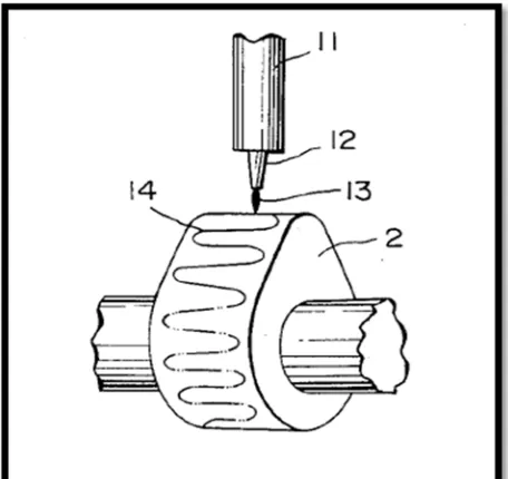
For such camshaft, the cam surface is chilled to get high hardness containing
transformed ledeburite without graphite during primary crystallization (Li Ping , Li
[image:20.612.117.345.391.606.2]Fengjun , Cai Anke2 and Wei Bokang, 2009).
Figure 1.1: A schematic perspective view showing a manner of a remelting treatment to
6
2.1.2 Ceramic
The present invention relates in general to a camshaft for an engine, and more
particularly to a structure of such an engine camshaft by using a ceramic material, which
is improved in wear resistance and durability and reduced in weight.
In the valve train car engine, wear and abrasion of the components, particularly
camshaft and rocker arms that having sliding surfaces, are a serious problem that should
be considered and overcome for improving the durability of the engine. These camshaft
used in the valve train car engine are usually made of cast iron, and their sliding surfaces
are chilled or hardened by heat treatment to increase the wear resistance against friction.
Efforts have been made to enhance the durability of the rocker arms. For example, the
sliding surfaces of the rocker arms is made of cast iron that can be nitrided or coated with
a hard-chrome plating layer.
In order to follow up with recent technological progress, engines of automotive
vehicles are struggle to provide higher performance and capability. On the other hand,
their invention are needed for controlling emissions from the engine. As a result to fulfill
the emission control requirements, the lubricating conditions or environments of the
engine are aggravated. Under these circumstances, further improvements are needed for
the cams which are formed as longitudinally spaced-apart integral sections of a camshaft,
and of the rocker arms in sliding contact with the camshaft, so as to increase the wear
resistance of their sliding surfaces, more specifically, resistance to pitting and scuffing of
the sliding surfaces.
At this end, various studies have been made for use as camshafts and rocker arms.
In other things, special attention of the industry has been paid to produce a composite
7
different from the material of the shaft portion. In general, the cam portions of such a
composite camshaft may be made of a ceramic material. However, a ceramic material for
the cam portions and the other material for the shaft portion have very different properties.
Therefore, there will arise a problem of how these two different materials will united
together into an integral assembled composite camshaft
2.2 Tappet
Tappet is the term that widely used to associate with internal combustion engines.
It usually refer as a maintenance job for overhead valve engines, for adjusting the tappets.
It is done by adjusting or modified the overall clearance in the valve system. The name
of tappetborn as it is clearance from the tappets are adjusted, although the adjustment
[image:22.612.117.323.374.680.2]was not made by the tappets themselves.
8
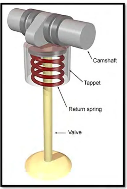
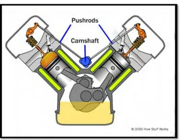
When we talk about the tappet, it consist of the part which can be known as
camshaft follower that located on the camshaft and is created to contact vertically by
rotation of the camshaft. In pushrod engine, this tappet is located down in the engine
block, from there it will push the pushrod to the top of the engine by rotation of camshaft.
In cylinder head the rockers arm are arranged on a rocker shaft, it then will push the valves
[image:23.612.118.489.228.516.2]downwards to open them.
Figure 2.2: How camshaft open the valve via pushrod
Earlier tappets consist of rollers to reduce wear and tear from the rotating camshaft,
but it was found that the roller pivots wear more rapidly than camshaft. The engineers
then produce a plain flat ends tappet, the shape were slightly radiuses as 'mushroom'
9
As to overcome wear problem from the rotation of the camshaft, the tappets were
usually crated circular shape and allowed it to rotate. This will prevent grooves generating
from the same point of the camshaft. In some internal combustion engines, commonly in
[image:24.612.115.340.192.340.2]V8 engines with a limited space, the tappets were small and non-rotating.
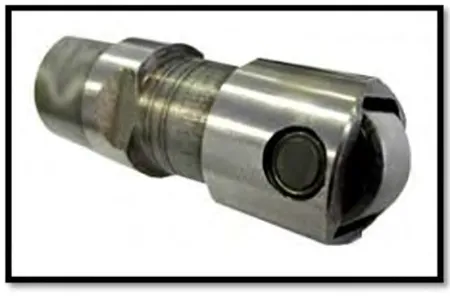
Figure 2.3: The hydraulic lifter
A hydraulic valve lifter, which is also known as a hydraulic tappet or
a hydraulic adjuster. It is created to ensure no valve clearance in an engine for optimum
performance. General valve lifters is required in regular adjusting to retain a small amount
of clearance between the valve and its rocker arm. The space or valve clearance is allowed
for thermal expansion between them, and prevented the parts from stick that can cause
friction and wear. According Cemal BAYKARA, Mehmet PALABIYIK (2002),
Hydraulic systems increase engine performance and efficiency by improving valve timing
and reducing maintenance need and improving comfort by eliminating clearances.