SUPERVISOR DECLARATION
“I hereby declare that I have read this thesis and in my opinion this report is sufficient in term of scope and quality for the award of degree of Bachelor of
Mechanical Engineering (Automotive)”
EXPERIMENTAL STUDY OF STEERING WHEEL VIBRATION IN DYNAMIC CONDITION
WAZIRTANI BIN OTHMAN @ ABDULLAH
This report is provided to fulfill the requirement of the term and condition for the award of degree of Bachelor of Mechanical Engineering (Automotive)
Fakulti Kejuruteraan Mekanikal Universiti Teknikal Malaysia Melaka
ii
DECLARATION
“I hereby declare that the work in this report is my own except for summaries and quotations which have been duly acknowledged.”
Signature : ...
Author : WAZIRTANI BIN OTHMAN @ ABDULLAH
iii
ESPECIALLY FOR
iv
ACKNOWLEDGEMENTS
I would like to express my sincere appreciation and gratitude for the infinite to the supervisor, Mr. Mohd Adrinata Bin Shaharuzaman for his guidance and
encouragement given during this Bachelor project lead.
v
ABSTRACT
vi
ABSTRAK
vii
CONTENT
CHAPTER ITEM Pages
Declaration ii
Dedication iii
Acknowledgement iv
Abstract vi
Abstrak v
Content vii
List of Table x
List of Figure xi
List of Symbol xv
List of Appendices xvi
CHAPTER 1 INTRODUCTION
1.0 Background 1
1.1 Problem Statement 3
1.2 Objectives 4
1.3 Scopes 5
CHAPTER 2 LITERATURE REVIEW
2.0 Introduction 6
2.1 Steering Wheel Fundamental 6
2.1.1 Rack and Pinion System 7
2.1.2 Recirculating Ball Bearing 8
2.1.3 Power Steering System 8
2.1.4 Steering Wheel 9
viii
2.2.1 Definition of Vibration 11
2.2.2 Vehicle Vibration 12
2.2.3 Human Vibration 13
2.3 Experimental Methodology 19
2.3.1 Introduction 19
2.3.2 Previous Study 19
2.4 DEWESOFT Software 22
2.5 DACTRON RT-PRO Software 22
CHAPTER 3 METHODOLOGY
3.0 Introduction 23
3.1 Methodology Flow Chart 24
3.2 Experimental of Modal Analysis for a Steering Wheel in Free-Free Boundary Condition
(By using DEWESOFT) 26
3.2.1 Background of Experiment 26 3.2.2 Objective of Experiment 26
3.2.3 Scope of Experiment 27
3.2.4 Apparatus 27
3.2.5 Procedure of Experiment 31 3.3 Experimental of Modal Analysis for a Steering
Wheel in Free-Free Boundary Condition
(By Using Dactron Rt-Pro) 38
3.2.1 Background of Experiment 38 3.2.2 Objective of Experiment 38
3.2.3 Scope of Experiment 39
3.2.4 Apparatus 39
3.2.5 Procedure of Experiment 43 3.3 Experimental of Modal Analysis for a Steering
Wheel in Constraint Condition 49
3.3.1 Background of Experiment 49 3.3.2 Objective of Experiment 49
3.3.3 Scope of Experiment 50
ix
3.3.5 Procedure of Experiment 54 3.2 Experimental on Highest Vibration of Steering
Wheel Vibration in Dynamic Condition 59 3.2.1 Background of Experiment 59 3.2.2 Objective of Experiment 59
3.2.3 Scope of Experiment 60
3.2.4 Apparatus 61
3.2.5 Procedure of Experiment 64
CHAPTER 4 RESULT AND ANALYSIS
4.0 Introduction 70
4.1 Result
4.1.1 Experimental Modal Analysis for Steering Wheel in Free-free Condition
.By Using Dewesoft Software 71 4.1.2 Experimental Modal Analysis for
Steering Wheel in Free-free Condition.
By Using Dactron RT-PRO Software 72 4.1.3Experimental Modal Analysis of the
Steering Wheel in Constraint Condition.
By Using Dactron RT-PRO Software 76 4.1.4Experimental Modal Analysis for
Steering Wheel in Dynamic Condition.
By Using Dactron RT-PRO Software 78
CHAPTER 5 CONCLUSION
5.0 Conclusion 88
REFERENCES 91
BIBLIOGRAPHY 91
x
LIST OF TABLE
TABLE. TITLE PAGE
Table 2.8 Magitude To Comfort For Passenger In
Public Transport 15
Source: R. Hopcroft and M. Skinner, C-130J Human Vibration (2005) Table 4.1 Summary Result for All Number of
Steering Wheel Spoke 63
Table 4.2 Summary of the Free-Free Boundary
Experimental Result 65
Table 4.3 Comparison between DEWESOFT and
Rt-Pro Result 66
Table 4.4 Summary of Experiment on Constraint
Condition 68
Table 4.5 Summary Result of the Experiment in
Dynamic Condition (Lower Gear) 75
Table 4.6 Summary Result of the Experiment in
Dynamic Condition (2nd Gear) 75
Table 4.7 Summary Result of the Experiment in
xi
LIST OF FIGURE
FIGURE. TITLE PAGE
Figure 2.1 Rack and Pinion Steering System 7 (Source: www.motorera.com/dictionary)
Figure 2.2 Recirculating Ball Bearing Steering System 8 (Source: http://auto.howstuffworks.com/steering3.htm)
Figure 2.3 Power Steering Systems 9
(Source: http://www.murphystyrepower.com.au/ power_steering.html)
Figure 2.4 Different Types of Steering Wheels 9 (Source: http://www.storesonline.com/site/564545/
product/400-110)
(Source: http://www.hondacarindia.com/city/ transmission.aspx)
Figure 2.5 Different Types of Frequency 10
(Source: http://www-classes.usc.edu) Figure 2.6 Source of Vehicle Vibration (Engine,
Road Condition, Suspension) 12
(Source: http://www.grc.nasa.gov/WWW/K-12/ airplane/lubesys.html)
(Source: http://www.pakwheels.com/forums/ guess-humor-hobbies/38995-funny-wheels-gifs-3) (Source: http://www.salvatoreaiello.com/
xii
FIGURE. TITLE PAGE
Figure 2.7 Whole Body Vibration 13
(Source: http://www.bksv.com/library/ dictionary.aspx?key=W)
Figure 2.8 Hand Arm Vibration 13
(Source: http://labor.state.ak.us/lss/pads/ hand-arm.htm)
Figure 2.9 Test Rig BSI 7809 17
[image:13.595.108.512.63.760.2]Source: J. Giacomin, Y.J. Woo (2005). Figure 2.10 Steering Wheel Vibration Most Popular
Holding Position 18
Source: J. Giacomin and S Gnanasekaran,(2005) Figure 2.11 Steering Wheel Most Popular Vibrations
Factor 18
Source: Dian D.I.D (2008)
Figure 3.1 Table And Hanger Jigs 24
Figure 3.2 Accelerometer 24,35,42
Figure 3.3 Different Type of Steering Wheel Spokes 25,35,42
Figure 3.4 Dactron 25
Figure 3.5 5mm Nut 25,36,43
Figure 3.6 Strong Glue For Metal To Plastic 25,36,43
Figure 3.7 Impact Hammer 26,36
Figure 3.8 Plastic Rope 26
Figure 3.9 Host PC 26
Figure 3.10 DEWESOFT Software 26
Figure 3.11 Attach The Nut Using Strong Adhesive 27,38,45 Figure 3.12 Bayonet Neill-Concelman (BNC) Cable
And Integrated Circuit Piezoelectric (ICP)
Signal Conditioning 27
Figure 3.13 Hanging the Steering Wheel at the Hanger Jig 28 Figure 3.14 Fixing Accelerometer at the Nut by Using
xiii
FIGURE. TITLE PAGE
Figure 3.15 DEWESOFT Programme 29
Figure 3.16 Changing Channel Mode 30
Figure 3.17 Channel Set Up For Channel 2 31
Figure 3.18 Spectrum Analyzer Mode Window 31
Figure 3.19 FFT Option 32
Figure 3.20 Impact the Steering Wheel at the
Centre Upper 33
Figure 3.21 Analyze Windows
(Time Line, Natural Frequency) 34
Figure 3.22 Perodua Kancil Automatic Transmission 35,42 Figure 3.23 Liberty 16 Channel For Portable /
Integrated Circuit Piezoelectric (ICP) Signal
Conditioning Channel for Portable 35,43, 45 Figure 3.24 Host PC Installed With Liberty Programme 36,44 Figure 3.25 Positions of the Accelerometers at the
Steering Wheel. 39, 46
Figure 3.26 The Position of Accelerometer:
Steering Wheel (1), Steering Column (1),
Bottom of the Column (1) 47
Figure 3.27 LDS Dactron Data Aquisition 36
Figure 3.28 Host PC 38
Figure 3.29 Dactron RT-PRO Software 38
Figure 3.30 Dactron LDS Data Aquisition 39
Figure 3.31 Example Result from RT-PRO 43
xiv
FIGURE. TITLE PAGE
Figure 4.7 Result of 2 Spoke at Lower Gear
(Dynamic Condition) 70
Figure 4.8 Result of 2 Spoke at 2nd Gear
(Dynamic Condition) 70
Figure 4.9 Result of 2 Spoke at Drive Gear
(Dynamic Condition) 71
Figure 4.10 Result of 3 Spoke at Lower Gear
(Dynamic Condition) 71
Figure 4.11 Result of 3 Spoke at 2nd Gear
(Dynamic Condition) 72
Figure 4.12 Result of 3 Spoke at Drive Gear
(Dynamic Condition) 72
Figure 4.13 Result of 4 Spoke at Lower Gear
(Dynamic Condition) 73
Figure 4.14 Result of 4 Spoke at 2nd Gear
(Dynamic Condition) 73
Figure 4.15 Result of 4 Spoke at Drive Gear
xv
LIST OF SYMBOL
BNC = Bayonet Neill-Concelman BS = British Standard
DAQ = Data Acquisition System HAV = Hand Arm Vibration Hz = Frequency, Hertz
ICP = Integrated Circuit Piezoelectric ISO = International Standard Organization m/s2 = Frequency, Metre/Second2
NVH = Noise, Vibration and Harshness WBV = Whole Body Vibration
xvi
LIST OF APPENDICES
NO TITLE PAGE
A Result from Free-free Boundary Experiment
(Using Dewesoft) 2-spoke Steering Wheel 92 B Result from Free-free Boundary Condition Experiment
(Using Dewesoft) 3-spoke Steering Wheel 94 C Result from Free-free Boundary Condition Experiment
(Using Dewesoft) 4-spoke Steering Wheel 96 D Result from Free-free Boundary Condition Experiment
(Using Dactron RT-PRO) 98
E Result from Constraint Boundary Condition Experiment
(Using Dactron RT-PRO) 100
F Result from Dynamic Condition Experiment
(Using Dactron RT-PRO) 102
G Gantt chart for Final Year Project 1 107
1
CHAPTER 1
INTRODUCTION
1.0 BACKGROUND
2
Each part of the car has been study to bring more customer satisfaction including the steering system. Steering system is very important subsystem in a vehicle. The steering system use to control the direction of the vehicle. The steering system is designed to control the direction of the front wheels over all types of the road conditions, through turns, and at different speeds. It is made of a linkage system that is attached to the front wheel, the steering wheel and the steering gear. As the drivers turn the steering wheel, the steering gear transfers this motion to a steering linkage and then the steering linkage turns the wheels to control the vehicle direction. There are 2 common types of steering system which is rack and pinion type and recirculating ball steering system. There also modern type of steering system which is very popular used is modern car which is power steering system that use hydraulic pump.
Comfort is the main demand from the customers. Each aspect of the car is important to be comfort and user friendly. The technologies apply are useless if there no comfort in the car. The comfort of the car is where the car in static and dynamic condition. Ergonomic study is the major comfort factor in a car. Besides that, the noise, vibration and harshness (NVH) is also the factor affecting the comfort of the car. In static and also dynamic condition, mostly the noise and the vibration came from the engine. Under idle conditions, the engine can be considered to represent the major source of vibration and sound which is transmitted to the driver within the vehicle cabin (M. Ajovalasit and J. Giacomin, 2008).
The vibration to human can divided into 2 categories which is whole body vibration (WBV) and hand arm vibration (HAV). At static condition which is due to engine only but in dynamic condition, suspension, road condition, surrounding effect like wind also effecting the vibration of the vehicle. Eliminating the vibration is impossible but car manufacture tries to reduce it to give comfort to the customer.
3
1.1 PROBLEM STATEMENT
1. The steering wheel vibration in dynamic condition cause discomfort for driver. This study is to find the source of the vibration and reduce it to comfortable frequency.
“Even slight fluctuations of engine idle can cause unpleasant vibration and sound emissions leading to lower customer satisfaction”
Hoard and Rehagen, 1997)
“Of these vibrating surfaces, the steering wheel is particularly important due to the great sensitivity of the skin tactile receptors of the hand. (J. Giacomin and S. Gnanasekaran, 2005)
“The sensations produced by the vibration stimuli which reach the vehicle driver can provide important information regarding the dynamic state of the vehicle, but can also provide annoyance and discomfort”(M.S. Shayaa , J.A Giacomin, E. Dormegnie and L. Richard, 2001)
4
1.2.1 OBJECTIVES
1. To conduct experimental modal analysis for a steering wheel
The purpose of this research is to conduct an experimental modal analysis for a steering wheel to find the natural frequency of the steering wheel. For the experimental modal analysis, 2 experiments will be conducted which are a free-free boundary and constraint condition. In both experiment, resonance frequency and the mode shape of the steering wheel will be determine by using impact hammer and accelerometers fixed at the steering wheel.
2. To study the behaviour of steering wheel vibration
In this research, sensors will be fixing at the steering wheel, and the rack to monitor the behaviour of the steering wheel vibration.
3. To analyze the highest vibration level for a car in dynamic condition
5
1.2.2 SCOPES
1. National compact car with front wheel drive and non-power steering
In this experiment, Perodua Kancil 660EZ automatic transmission type to fulfil the scope. Perodua Kancil is national compact car with front wheel drive and non power steering.
2. Experimental analysis for the steering wheel for free-free boundary condition and constraint condition.
Free-free boundary condition is where the steering wheel will be hang and impact with impact hammer to find the natural frequency of the steering wheel. For constraint condition, the impact test for the steering wheel will be doing in the car with full assembly of the steering system.
3. Moving Passenger Car (Dynamic Condition)
6
CHAPTER 2
LITERATURE REVIEW
2.0 INTRODUCTION
For this research, there are a lot of literature reviews about steering system, vibration which include whole body vibration (WBV) and hand-arm vibration (HAV). There are also some literature review for experimental methodologies which are Free-free Boundary Condition Impact Test and Constraint Condition Impact Test. For the equipment and software that had been use, there is some literature review to validate the results.
2.1 STEERING SYSTEM FUNDAMENTAL
7
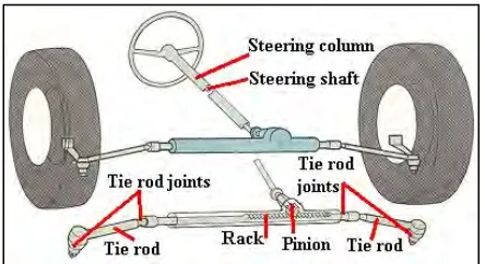
the outer wheel, so that the degree of toe suitable for driving in a straight path is not suitable for turns. There are basically two types of vehicle steering systems, rack and pinion and recirculating ball bearing system.
2.1.1 Rack and Pinion System
[image:24.612.208.430.396.517.2]The rack and pinion steering is one of the oldest types of steering systems which is still used today. Inside the rack body a flat rack gear moves in linear direction driven by a circular gear called a pinion. The steering wheel is connected to the pinion gear (shaft). The rack gear is connected to an inner tie rod end that is covered by a rubber below. The inner tie road end connected to the outer tie road end. These rod ends have the ability to move in any linear direction. Finally, the tie rod end is connected to the wheel spindle.