PRODUCT DEVELOPMENT USING REVERSE ENGINEERING (RE) APPROACH
MOHD SHAFFRAN BIN ZAINAL RASHID
A report submitted in partial fulfillment of the requirement for the award of the Degree of Bachelor of Mechanical Engineering
(Design and Innovation)
Faculty of Mechanical Engineering Universiti Teknikal Malaysia Melaka
I hereby declare that I have read this thesis and in my opinion this report is sufficient in terms of scope and quality for the award of the
Bachelor of Mechanical Engineering (Design and Innovation)
Signature :
Name of supervisor : Mr. Hambali Bin Boejang Date :
Signature :
I declare that this report entitled “PRODUCT DEVELOPMENT USING REVERSE ENGINEERING (RE) APPROACH” is the result of my own research
except as cited in the references. The report has not been accepted for any degree and is not concurrently submitted in candidature of any other degree.
ACKNOWLEDGEMENT
First of all I would like thanks to ALLAH S.W.T because give me a chance to finish my report for Projek Sarjana Muda. Besides that, I also would like to take this opportunity to empress my regards to my supervisor, Mr. Hambali Bin Boejang, Faculty of Mechanical Engineering, UTeM, for his help, advice and guideline for me to understand the project and complete the report.
I want to thank to the technicians who had give information that help me to do the project. I also would like thanks to my colleagues especially to my housemate for their generosity in spending their time and providing me a lot of knowledge during my literature review and sharing their opinion and encouragement in my process of accomplished my Projek Sarjana Muda.
ABSTRACT
TABLE OF CONTENT
CHAPTER TITLE PAGE
ACKNOWLEDGEMENT iii
ABSTRACT iv
TABLE OF CONTENT v
LIST OF TABLE ix
LIST OF FIGURE x
LIST OF ABBREVIATION xiii
CHAPTER 1 INTRODUCTION
1.1 Introduction of the project 1
1.2 Aim 1
1.3 Objective 2
1.4 Scope 2
1.5 Flow chart of PSM 1 3 1.6 Flow chart of PSM 2 4
CHAPTER 2 LITERATURE REVIEW
2.1.5 Typical Workflow in
Reverse Engineering 9 2.1.6 Non Uniform Rational B-Spline
(NURBS) 13 2.1.7 Application of Reverse Engineering 14
2.2 COMPUTER AIDED DESIGN (CAD) 15 2.2.1 Introduction to Computer Aided
Design 15 2.2.2 Types of Modeling 16 2.2.2.1 Solid Modeling 16 2.2.2.2 Surface Modeling 17 2.2.3 Advantages and Disadvantages of
CAD 18
2.2.4 Capabilities of CAD 19 2.2.5 STL File Format 20 2.2.5.1 Advantages and Disadvantages of STL file format 20 2.3 RAPID PROTOTYPING (RP) 21
2.3.1 Introduction of Rapid Prototyping 21 2.3.2 Advantages of Rapid Prototyping 21 2.3.2.1 Direct Benefits 21 2.3.2.2 Indirect Benefits 22 2.3.3 Classification of Rapid Prototyping
System 22
2.3.4 Types of Rapid Prototyping 29 2.3.4.1 Subtractive Process 29 2.3.4.2 Addictive Process 30 2.3.4.3 Formative Process 30
2.3.5 Rapid Prototyping Process Chain 30 2.3.6 Application of Rapid Prototyping 32
CHAPTER 3 METHODOLOGY
3.1 Introduction 33 3.2 Project Development Flow Chart 33 3.3 Project Definition and Planning 34 3.4 Reverse Engineering Phase 35 3.5 Computer Aided Design Phase 36 3.6 Rapid Prototyping Phase 37 3.7 Comparison Phase 38
CHAPTER 4 RESULT
4.1 Motorcycle Tail Lamp 40 4.1.1 The Outside Surface 40 4.1.2 The Inside Surface 41
4.2 Reference Point 42
4.3 Reverse Engineering Using
REXCAN/ ezScan 4.5 42
4.3.1 Surface 46
4.4 Analysis the Comparison of RE CAD Data
with Scanned Object 55
CHAPTER 5 DISCUSSION
5.1 Analysis 60
5.2 Scanned Data Problem 62 5.3 Analysis Problem 68 5.3.1 Data Translation Problem 68
5.3.2 Magics RP 69
5.3.3 Insight Software 72
CHAPTER 6 CONCLUSION AND RECOMMENDATION
6.1 Conclusion 75
6.2 Recommendation 76
REFERENCES 77
LIST OF TABLE
TABLE NO TITLE PAGE
LIST OF FIGURE
FIGURE NO TITLE PAGE
1.1 Flow Chart of PSM 1 3 1.2 Flow Chart of PSM 2 4 2.1 Principles of A Laser Triangulation Sensor 8
2.2 Cloud Point 9
2.3 Polygonal Model 10 2.4 Draw Curves on the Mesh 10 2.5 Restructured Spring 11 2.6 NURBS Surfaces 11 2.7 Final Result of NURBS Surface 12
2.8 Final Object 12
2.9 NURBS Control Point and Control Polygon 13 2.10 The CAD Process 15 2.11 A Design Drawing for An Engine 17 2.12 A CAD Model of A Mouse 18 2.13 Diagram of Stereolithography Apparatus 23
2.14 Viper Si2 23
3.5 Rapid Prototyping Phase Process 38 3.6 Comparison Phase Process 39 4.1 Outside Surface of the Tail Lamp 41 4.2 Inside Surface of the Tail Lamp 41 4.3 Reference Point 42 4.4 Scanned Object at Scanned Table 43 4.5 Camera Window of REXCAN 43 4.6 Adjustment of the Distance 44 4.7 Adjustment of the Brightness 45 4.8 Scanned Process 45 4.9 The Scanned Object Spray With
4.29 Holes of the Scanned Data 59 5.1 General of The Project Flow 60 5.2 REXCAN 3D Scanner 61 5.3 Missing Faces 62
5.4 Fill Holes 63
5.5 Fill Holes Popup Menu 63
5.6 Smoothing 64
5.7 Smoothing Popup Menu 65 5.8 Improve Shape Quality 66 5.9 Before Add Faces 66 5.10 After Add Faces 67 5.11 Scanned Data in Magics RP Software 69 5.12 Scanned Data In Triangle View 69 5.13 Before Error Recovery 70 5.14 After Error Recovery 71 5.15 Insight Workspace 72 5.16 Processing Model 73
LIST OF ABBREVIATION
2D Two Dimensions 3D Three Dimensions CAD Computer Aided Design
CAM Computer Aided Manufacturing FDM Fused Deposition Modeling NURBS Non-Uniform Rational B-Spline RE Reverse Engineering
RP Rapid Prototyping
CHAPTER 1
INTRODUCTION
1.1 Introduction of the project
The engineering field is growth faster. The new product, new technology or new system has been introduced. In engineering field, Computer Aided Design (CAD) is familiar to engineers. CAD is making the design faster and effective. However, the manual drafting and sketching still been used by engineers.
There are new technologies that are now growth within time. Reverse Engineering (RE) and Rapid Prototyping (RP) are the new technologies that now all the engineers are learned. Reverse Engineering (RE), Computer Aided Design (CAD) and Rapid Prototyping (RP) are related together. These three technologies are making the engineering field easier to produce and analysis any part or product.
1.2 Aim
manipulated to obtain the 3D CAD data. This 3D CAD data is then used in RP machine to make the prototype.
1.3 Objective
The objective of this thesis is to apply a product development by using Reverse Engineering (RE) approach. In this thesis, motorcycle tail lamp is the product that will be developed by using Reverse Engineering (RE), Computer Aided Design (CAD) and Rapid Prototyping (RP) method.
1.4 Scope
The scope of this thesis is to:
I. Study on the Reverse Engineering (RE), Computer Aided Design (CAD) and Rapid Prototyping (RP).
II. Manipulate the scanned data to obtain the CAD data for the motorcycle tail lamp.
III. Create a prototype of the product using RP machine. IV. Compare the existing part to the prototype part.
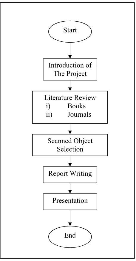
1.5 Flow Chart of PSM 1
End Presentation Report Writing Scanned Object
Selection Literature Review
i) Books ii) Journals
Introduction of The Project
Start
[image:21.612.230.458.146.581.2]1.6 Flow Chart of PSM 2
Cont. from PSM 1
CHAPTER 2
LITERATURE REVIEW
2.1 REVERSE ENGINEERING (RE)
2.1.1 Introduction of Reverse Engineering (RE)
Reverse Engineering (RE) is the process of capturing the 3 Dimension object form and transfer to a computer compatible representation. RE is also a process of creating engineering design data from the existing part. In some cases, RE is necessary only to extract 2 Dimension profile data from the model as the complete part may be efficiently modeled using these profiles and a surface or solid Computer Aided Design (CAD) / Computer Aided Manufacturing (CAM) system [1]. There are several methods that the object form can be captured for RE. The method chosen is depending on the object complexity and accuracies requirement from the digitization process [2]. The first step of RE in the process to produce the product is the physical model to CAD data. The next step of the RE is to convert the CAD data into a usable form.
2.1.2 Common uses of Reverse Engineering
• As a learning tool.
• As a way to make new compatible product.
• For making software interoperate more effectively.
2.1.3 Type of Reverse Engineering
The simple models can be measured with vernier calipers and recreated in the CAD system based on measurements. However, for the complex model, there are two type of RE which is contact and non-contact.
2.1.3.1 Contact Method
Co-ordinate Measuring Machine (CMM) is the contact method. CMM provides higher accuracy in the micron range but it is subject to slow the data sampling times. CMM takes the data by a touch probe. It touches the part surface using the probe at a certain point. The surface scanning CMM can take the sample at one point per second. The less sophisticated CMM has much lower data collection rates. CMM is more high accuracy than the 3D Vision System. The disadvantage of CMM is it touches the scanned object. Thus, the act of scanning the object might modify or damage it. This contact method is very significant when scanning valuable objects such as historical artifacts. The other disadvantage of CMMs is that they are relatively slow compared to the other scanning methods. Physically moving the arm that the probe is mounted on can be very slow and the fastest CMMs can only operate on a few hundred hertz [3].
2.1.3.2 Non-Contact Method