UNIVERSITI TEKNIKAL MALAYSIA MELAKA
DESIGN, OPTIMIZATION AND DEVELOPMENT OF
PHYLLOTAXIS PATTERN SOLAR PANEL
This report is submitted in accordance with the requirement of Universiti Teknikal Malaysia Melaka (UTeM) for the Bachelor of Mechanical Engineering Technology
(Automotive Technology) with Honours
by
ONG QIAO YUAN B071410201 940108106086
iv
UNIVERSITI TEKNIKAL MALAYSIA MELAKA
BORANG PENGESAHAN STATUS LAPORAN PROJEK SARJANA MUDA
Tajuk: Design, Optimization and Development of Phyllotaxis Pattern Solar Panel
SESI PENGAJIAN: 2017/18 Semester 1
Saya ONG QIAO YUAN
mengaku membenarkan Laporan PSM ini disimpan di Perpustakaan Universiti Teknikal Malaysia Melaka (UTeM) dengan syarat-syarat kegunaan seperti berikut:
1. Laporan PSM adalah hak milik Universiti Teknikal Malaysia Melaka dan penulis. 2. Perpustakaan Universiti Teknikal Malaysia Melaka dibenarkan membuat salinan
untuk tujuan pengajian sahaja dengan izin penulis.
3. Perpustakaan dibenarkan membuat salinan laporan PSM ini sebagai bahan pertukaran antara institusi pengajian tinggi.
4. **Sila tandakan ( )
SULIT
TERHAD
TIDAK TERHAD
(Mengandungi maklumat yang berdarjah keselamatan atau kepentingan Malaysia sebagaimana yang termaktub dalam AKTA RAHSIA RASMI 1972)
(Mengandungi maklumat TERHAD yang telah ditentukan oleh organisasi/badan di mana penyelidikan dijalankan)
Alamat Tetap:
No. 154, Jalan BS 6/7,
Taman Bukit Serdang,
43300 Seri Kembangan, Selangor.
Tarikh: ___3/1/2018____________
Disahkan oleh:
Cop Rasmi:
Tarikh: _______________________
iv
DECLARATION
I hereby declared this report entitled “Design, Optimization and Development of Phyllotaxis Pattern Solar Panel” is the result of my own research except as cited in
references.
Signature :
Author’s Name : ONG QIAO YUAN
v
APPROVAL
This report is submitted to the Faculty of Engineering Technology of UTeM as a partial fulfilment of the requirements for the degree of Bachelor of Mechanical Engineering Technology (Automotive Technology) with Honours. The member of the supervisory is as follow:
vi
ABSTRAK
vii
ABSTRACT
viii
DEDICATION
To my beloved parents
Ong Sing Teck Choong Yoke Thai
Thank you for all supports, sacrifices, patient and willing to spend your time for me.
To my honoured supervisor and co supervisor,
Dr. Abdul Munir Hidayat Syah Lubis, Encik Mohd Idain Fahmy bin Rosley and all UTeM lecturers
ix
ACKNOWLEDGEMENT
Foremost, I would like to express my sincere gratitude to my supervisor Dr. Abdul Munir Hidayat Syah Lubis of the Faculty of Engineering Technology at University Technical Malaysia Malacca for the continuous support of my Bachelor study’s final year project, for his patience, motivation, enthusiasm and immense knowledge. The door of Dr. Abdul Munir Hidayat Syah Lubis office was always opened whenever I ran into a trouble spot or had a question about my writing or concept design. He consistently allowed this paper to be my own work but steered me in the right direction whenever he thought I needed it. I could not have imagined having a better advisor and mentor for my Bachelor study’s final year project.
Besides my advisor, I would like to thank the rest of my thesis committee: Encik Mohd Idain Fahmy bin Rosley and Encik Wan Norhisyam bin Abd Rashid for their encouragement, insightful comments and hard questions. Without their passionate participation and input, the project could not have been successfully conducted. Moreover, I would like to express my gratitude to UTeM for funding Applied Oriented Research Grant (AORG) with serial number PJP/2017/FTK-AMC/S01562 for my project.
I would also like to acknowledge Muhammad Haziq Ilham bin Roslan of Faculty of Engineering Technology as the second reader of this thesis. I am gratefully indebted to his valuable comments on this thesis.
x
TABLE OF CONTENT
Abstrak vi
Abstract vii
Dedication viii
Acknowledgement ix
Table of Content x
List of Tables xiii
List of Figures xv
List of Abbreviations, Symbols And Nomenclature xviii
CHAPTER 1: INTRODUCTION 1
1.1 Project Background 1
1.2 Problem Statement 2
1.3 Objectives 3
1.4 Scopes 3
CHAPTER 2: LITERATURE REVIEW 4
2.1 Introduction 4
2.2 History of Solar Cell 6
2.3 Principle of Solar Cell 7
2.4 Material of Solar Cell 10
2.4.1 Monocrystalline Silicon Solar Cell 11
2.4.2 Polycrystalline Silicon Solar Cell 13
2.4.3 Thin Film Solar Cell 14
xi
2.5 Solar Cell Design 18
2.5.1 Adjustable Solar Powerer 18
2.5.2 Closable Solar Collector 19
2.5.3 Multi-Leaf Solar Energy Supplying Apparatus 20
2.5.4 Solar module 22
2.5.5 “Sunflower” Solar Power Station Based On Bionic Robot 23
2.6 Design of Photovoltaic System 24
2.7 Stepper Motor 28
CHAPTER 3: METHODOLOGY 30
3.1 Introduction 30
3.2 Experimental Design 30
3.3 Benchmarking Design 32
3.3.1 Adjustable Solar Powerer 32
3.3.2 Closable Solar Collector 33
3.3.3 Multi-Leaf Solar Energy Supplying Apparatus 34
3.3.4 Solar Module 35
3.3.5 “Sunflower” Solar Power Station Based On Bionic Robot 36
3.4 Concept Design of Base/Foot Of Solar Panel 37
3.5 Solar Panel Concept Generation 38
3.6 Solar Panel Erection Mechanism Concept Generation 41
3.7 Concept Selection 42
3.8 Mechanism 45
3.9 Material Selection 46
3.10 Circuit Design 48
3.11 Analysis 50
xii
CHAPTER 4: RESULT AND DISCUSSION 53
4.1 Introduction 53
4.2 Concept Selection 53
4.3 Mechanism 55
4.3.1 Open-Close Mechanism of Blade 55
4.3.2 Erection Mechanism of Solar Panel 59
4.4 Electrical Output 61
4.5 Optimisation of Solar Cell Output 68
4.6 Stress Analysis of Solar Panel Assembly Structure 70
CHAPTER 5: CONCLUSION AND FUTURE WORK 77
5.1 Introduction 77
5.2 Conclusion 77
5.3 Future Work 78
REFERENCES 80
APPENDICES 84
A. Gantt Chart 84
B. Table of Weather Forecast 86
C. General Report of Catia V5 Analysis 88
C.1 Stand Straight Honeycomb Pattern Stand Bar 88
C.2 Slanted Honeycomb Pattern Stand Bar 94
xiii
LIST OF TABLES
Table 3.1: Comparison between advantage and disadvantage of adjustable solar
powerer 32
Table 3.2: Closable solar collector 33
Table 3.3: Multi-leaf solar energy supplying apparatus 34
Table 3.4: Solar module 35
Table 3.5: “Sunflower” solar power station based on bionic robot 36
Table 3.6: Sun position in Malacca according to time 37
Table 3.7: Rating scale for concept scoring 43
Table 3.8: Concept scoring for blade concept design 44
Table 3. 9: Concept scoring for erection mechanism concept design 45
Table 3. 10: Coil End Wire Pairing 47
Table 3. 11: Resistance Reading of wire pair for coil winding 1 and coil
winding 2 47
Table 4. 1: Concept scoring for blade concept design 54
xiv
Table 4. 3: Output data of a single solar cell 62
Table 4. 4: Output data of two solar cells connected in series 67
Table 4. 5:Output data of two solar cells connected in parallel 67
Table B. 1 : Weather forecast at Seri Kembangan in 20/11/2017 866
Table B. 2: Weather forecast at Batu Berendam, Melaka in 21/11/2017
and 22/11/2017 866
xv
LIST OF FIGURES
Figure 2.1: Phyllotaxis pattern under cylindrical view 5
Figure 2.2: Phyllotaxis pattern under centric view 5
Figure 2.3: PN junction in semiconductor 8
Figure 2.4: Energy band diagram 10
Figure 2.5: Czochralski process 12
Figure 2.6: Siemen process 14
Figure 2.7: Thin film solar cell 15
Figure 2.8: Electron transfer mechanism in DSSCs 17
Figure 2.9: Adjustable solar powerer 19
Figure 2.10: Closable solar collector 20
Figure 2.11: Multi-leaf solar energy supplying apparatus 21
Figure 2.12: Solar module 22
Figure 2. 13: “Sunflower” solar power station based on bionic robot 24 Figure 2.14: Characteristic of cells connected in series 24 Figure 2.15: Characteristic of cells connected in parallel 25
Figure 2.16: Characteristics of Isc and Voc 26
Figure 2.17: 5-wire motor 28
Figure 2.18: 6-wire motor 29
xvi
Figure 3.1: Flowchart of methodology 31
Figure 3.2: Adjustable solar powerer 32
Figure 3.3: Closable solar collector 33
Figure 3.4: Multi-leaf solar energy supplying apparatus 34
Figure 3.5: Solar module 35
Figure 3.6: “Sunflower” solar power station based on bionic robot 36
Figure 3.7: Concept 1 (3 stages of closing) 38
Figure 3.8: Concept 2 (4 stages of closing) 39
Figure 3.9: Concept 3 (3 stages of closing) 40
Figure 3.10: Concept 4 (3 stages of closing) 40
Figure 3.11: Mechanism concept 1 41
Figure 3. 12: Mechanism concept 2 42
Figure 3.13: Schematic diagram of solar cell to battery circuit 49
Figure 3. 14: Mass of blade assembly 50
Figure 3. 15: Mass of stepper motor, stepper motor housing and honeycomb
pattern stand plate 51
Figure 3. 16: Mass of link bar 52
Figure 4. 1: Top view of fully open blade assembly 56
Figure 4. 2: Bottom view of fully open blade assembly 56
Figure 4. 3: Bottom view of Blade 1 57
Figure 4. 4: Top view of Blade 2 57
Figure 4. 5: Breadboard connection between Arduino Uno, stepper motor and
xvii Figure 4. 6: Isometric view of phyllotaxis solar panel 60 Figure 4. 7: Zoomed view of connection between honeycomb pattern stand plate
rod and link bar-sliding rod 61
Figure 4. 8: Connection between acrylic honeycomb stand with link bar 61 Figure 4. 9: Method of taking output data from solar cells 62 Figure 4. 10: Graph of Temperature versus Current and Voltage 64 Figure 4. 11: Current-voltage characteristics of the shaded PV module 64 Figure 4. 12: Graph of Cloudy Percentage versus Current and Voltage 65 Figure 4. 13: Output voltage of single solar cell, series connected solar cell and parallel connected solar cell 68 Figure 4. 14: Output current of single solar cell, series connected solar cell and
parallel connected solar cell 68
Figure 4. 15: Solar cell arrangement 70
xviii
LIST OF ABBREVIATIONS, SYMBOLS AND
NOMENCLATURE
Ag - Silver
Au - Gold
CdTe - Cadmium Telluride
CIGS - Copper Indium Gallium Selenide
CH4 - Methane
CO2 - Carbon Dioxide
DC - Direct Current
DSSC - Dye-Sensitised Solar Cell
eV - Electron volt
FF - Fill Factor
HF - Hydrofluoric Acid
HCL - Hydrochloric Acid
H2O2 - Hydrogen Peroxide
HF-HCL- H2O2 - Hydrofluoric Acid, Hydrochloric Acid and Hydrogen Peroxide
I - Current
Isc - Short Circuit Current
ITO/FTO - Indium/Fluorine Tin Oxide Glass JL,M - Current at Maximum Power Condition
Jo - Dark Current
Js - Short Circuit Current
JL,M - Current At Maximum Power Condition
K - Boltzmann Constant
NRAs - Zno Nanorod Arrays
N2O - Nitrous Oxide
NOx - Nitrogen Oxides
PI - Polyimide
Pt - Platinum
xix
SLG - Soda Lime Glass
SO2 - Sulphur Dioxide
T - Temperature at Kelvin
TCOs - Transparent Conductive Oxides
TiO - Titanium Dioxide
USB - Universal Serial Bus
Voc - Voltage Open Circuit
Vm - Voltage at Maximum Power
ZnO - Zinc Oxide
Ƞ - Efficiency
1
CHAPTER 1
INTRODUCTION
1.1 Project Background
There are uncountable cases of pollution happened in past 10 years. Pollution are categorised into different types for example sound pollution, air pollution, water pollution and etc. but all of them are threats to the Earth. If the issues are not taken care carefully, habitats of human, flora and fauna will be damaged and the future generation might going to live in a poor environment.
Electricity is first discovered by Benjamin Franklin. Electricity can be generated using different types of energy and these energy are also categorised into non-renewable energy and renewable energy. During the old times, electricity were generated mostly using non-renewable energy and it is still using now. The production of non-renewable energy uses the sources or materials that will be finished after use for example natural gas, coal, petroleum and diesel. Hence, the production of non-renewable energy requires tons of raw material which majority of the materials are obtained underneath the Earth surface.
2 does not give out harmful emission and the sunlight from the Sun is limitless, abundant and infinite.
Solar panel with phyllotaxis pattern is designed and fabricated to achieve the objective of this project. The main reason of applying phyllotaxis pattern concept into the design is to enable the solar panel to be opened and closed in the form of bloom flower so that the user can carry it along easily. The solar panel can be folded up and kept in a storage space to ease in transportation. The solar panel also designed to come with a USB port so that the user can connect the solar panel to other device easily.
1.2 Problem Statement
The common method used to generate electricity is by using fossil fuel either petroleum or diesel. Both types of fuel gives harmful emission to the environment. The generation of electricity that uses fossil fuel gives out greenhouse gases such as carbon dioxide (CO2), nitrous oxide (N2O) and methane (CH4) other than air pollutants such as sulphur dioxide (SO2) and nitrogen oxides (NOx).
3 1.3 Objectives
The objectives of this project are as follows:
i. To design phyllotaxis pattern solar panel.
ii. To fabricate prototype of phyllotaxis pattern solar panel. iii. To optimize the output of phyllotaxis pattern solar panel.
1.4 Scopes
i. Design phyllotaxis pattern solar panel using CATIA design software.
ii. Develop the electrical circuit as output of solar panel by modifying the circuit. iii. Fabricate the prototype and analyse electrical output of the prototype.
4
CHAPTER 2
LITERATURE REVIEW
2.1 Introduction
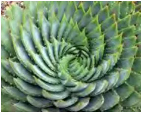
Phyllotaxis is the form that plant’s organs such as petal and leaf are arranged around the stem. Phyllotaxis form is not necessary to be the floret and leaf arrangement but it also can be the arrangement of fruitlets on pineapple, sunflower seeds on sunflower and the scales on pine cones (Korn, 2008). This kind of form has attracted numbers of botanist, biologist and mathematician to carry out studies towards it. Even Charles Darwin was frustrated to solve the mystery of the phyllotaxis arrangement in terms of the divergence angle of the plant’s organ with respect to its neighbour ones (Darwin, 1861).
5 Figure 2.1: Phyllotaxis pattern under cylindrical view (Seewald, 2017)
Figure 2.2: Phyllotaxis pattern under centric view (Retrieved from
http://produto.mercadolivre.stfi.re/MLB-695832344-20-sementes-suculenta-agave-mix-cactos-flor-p-mudas-planta-_JM?sf=ngwjzbe#aa)
[image:23.595.246.390.267.384.2]6 Phyllotaxis arrangement is an amazing creation from God as it maximises sunlight absorption with no overlapping of leaves with each other and hence enhances the photosynthesis process. These unique characteristics can be substituted into a solar panel arrangement design and helps in optimizes sunlight absorption and hence increases the energy conversion efficiency.
2.2 History of Solar Cell
Solar energy, the energy in the form of radiation from the Sun, is the most abundant, limitless and infinite energy. Solar energy as the precious gift from the Sun is used since ages to convert solar energy into various form of energy such as heat energy and recently, electricity (Silvi, 2008). Solar energy is said to be one of the favourable renewable energy in the world due to its emission-free characteristic, long lifetime of 20 to 30 years with low operation cost and little maintenance (Bagher, 2015). It is completely environmentally friendly form of energy hence a lot of studies and researches were carried out to maximize solar energy harvesting as the alternative solution to electricity generation using fossil fuel that produces waste products and lead to environmental pollution.