UNIVERSITI TEKNIKAL MALAYSIA MELAKA
THE DEVELOPMENT OF AUTOMATIC SWITCH USING
MICROCONTROLLER
This report submitted in accordance with requirement of the UniversitiTeknikal Malaysia Melaka (UTeM) for the Bachelor Degree of Engineering Technology
(Industrial Power)(Hons.)
by
NUR SHAHIRA BINTI ROSMI B071410550
951118035190
FACULTY OF ENGINEERING TECHNOLOGY
UNIVERSITI TEKNIKAL MALAYSIA MELAKA
BORANG PENGESAHAN STATUS LAPORAN PROJEK SARJANA MUDA
TAJUK: The Development of Automatic Switch Using Microcontroller
SESI PENGAJIAN: 2017/18 Semester 1
Saya NUR SHAHIRA BINTI ROSMI
Mengaku membenarkan Laporan PSM ini disimpan di Perpustakaan Universiti Teknikal Malaysia Melaka (UTeM) dengan syarat-syarat kegunaan seperti berikut: 1. Laporan PSM adalah hak milik Universiti Teknikal Malaysia Melaka dan penulis. 2. Perpustakaan Universiti Teknikal Malaysia Melaka dibenarkan membuat salinan
untuk tujuan pengajian sahaja dengan izin penulis.
3. Perpustakaan dibenarkan membuat salinan laporan PSM ini sebagai bahan pertukaran antara institusi pengajian tinggi.
4. **Sila tandakan ( )
SULIT
TERHAD
TIDAK TERHAD
(Mengandungi maklumat yang berdarjah keselamatan atau kepentingan Malaysia sebagaimana yang termaktub dalam AKTA RAHSIA RASMI 1972)
(Mengandungi maklumat TERHAD yang telah ditentukan oleh organisasi/badan di mana penyelidikan dijalankan)
AlamatTetap:
LOT 50 KAMPUNG LALOH, 18000 KUALA KRAI,
KELANTAN.
Tarikh: ________________________
Disahkan oleh:
Cop Rasmi:
Tarikh: _______________________
iii
DECLARATION
I hereby, declared this report entitled “THE DEVELOPMENT OF AUTOMATIC SWITCH USING MICROCONTROLLER” is the results of my own research
except as cited in references.
Signature : ……….
Author’s Name : NUR SHAHIRA BINTI ROSMI
iv
APPROVAL
This report is submitted to the Faculty of Engineering Technology of UTeM as a partial fulfillment of the requirements for the degree of Bachelor of Electrical Engineering Technology (Industrial Power) with Honours. The member of the supervisory is as follow:
v
ABSTRAK
Automatic Switch (AS) adalah sebuah sistem yang menggabungkan rangkaian
vi
ABSTRACT
vii
DEDICATION
To my beloved parents
Mr.Rosmi and Mrs.Azizah
Who was raised me
viii
ACKNOWLEDGEMENT
I would like to express my appreciation for those who help me to accomplish my project especially to my supervisor Mr Mohd Firdaus bin Mohd Ab. Halim for guiding me through the whole process of this project and thanks for those who are contributed in
ix
TABLE OF CONTENTS
Abstrak v
Abstract vi
Dedication vii
Acknowledgement viii
Table of Content ix-x
List of Tables xi
List of Figures xii
List Abbreviations, Symbols and Nomenclatures xiii
CHAPTER 1: INTRODUCTION
1.0 Introduction 1-2
1.1 Problem Statement 3
1.2 Objective 3
1.3 Scope 4
CHAPTER 2: LITERATURE REVIEW
2.0 Introduction 5
2.1 Literature Survey 5-8
CHAPTER 3: METHODOLOGY
3.0 Introduction 9
3.1 Wireless Switch (WS)
3.2.1 Operation for WS 10
3.2.2 Software Implementation 10-14
3.2.3 Hardware Implementation 15-16
3.3 Mechanical Switch (MS)
3.3.1 Flow Operation of MS 16
3.3.2 Software Implementation 17
x
CHAPTER 4: RESULT AND DISCUSSION
4.0 Introduction 20
4.1 Wireless Switch (WS) 20-23
4.2 Mechanical Switch (MS) 24-27
4.3 Power Consumption 28
CHAPTER 5: CONCLUSION
5.0 Introduction 29
5.1 Wireless Switch (WS) 29
5.2 Mechanical Switch (MS) 29
5.3 Future Work 30
REFERENCES 31
APPENDICES
A Coding for WS 32-33
B Coding for MS 34-37
C Datasheet Arduino Uno 38
D Datasheet Bluetooth Module HC05 39
E Datasheet Arduino Nano 40
xi
LIST OF TABLES
TABLES TITLE PAGES
3.1 3.2
4.1 4.2
List of component that being used in Wireless Switch List of component that being used in Mechanical Switch
Reliability of Wireless Switch to function (ON/OFF) Reliability of Mechanical Switch to function (ON/OFF)
19-20 27-29
xii
LIST OF FIGURES
FIGURES TITLE PAGES
3.1 Flow operation for WS 9
3.2 3.3 3.4 3.5 3.6 3.7 3.8
Coding of WS using MIT Inventor software system MIT Inventor App for WS
Android App for Control WS
Coding in Arduino software for whole operation of WS Simulation Proteus for WS
Flow operation for Mechanical Switch Simulation in Proteus for MS
11 12 12 13 14 16 17
4.1 An Application of WS in Android Phone 20
4.2 4.3 4.4 4.5 4.6 4.7 4.8 4.9
Simulation for Wireless Switch circuit in Proteus Wireless Switch
Simulation for Mechanical Switch circuit in Proteus Mechanical Switch
AC 20A switch Projector switch
Simulation Proteus for MS Simulation in Proteus for MS
xiii
LIST OF ABBREVIATIONS, SYMBOLS AND
NOMENCLATURE
AS -
App -
AC -
GND -
Hz -
IR -
LED -
MIT -
MS -
PIR -
TV -
USB -
V -
WS -
Automatic Switch Apparatus Alternating Current Ground Hertz Infrared Light-emitting diode
Massachusetts Institute of Technology Mechanical Switch
Passive infrared sensor Television
Universal Serial Bus Voltage
1
1.0 Introduction
The advances in the technologies related to wireless communication has led to the emergence of several engineering designs to aid the human requirements. Nowadays the vital part in our daily life is modern technology. Modern technology has made the requirement for information flow to be quick and effective. Day by day people are become more reliant on science and technology. Today, mobile phone is an element and useful devices of our daily life.
In this project, describe how to control and designing an Automatic Switch (AS) which act as plug and play device that control system which is based on microcontroller. AS consist of two parts which is first part Wireless Switch (WS) is about a system which can turn on and off a lamp wirelessly within shortage range by using mobile phone through Bluetooth device at range of 10 meter while the second part Mechanical Switch (MS) is about a system that can control electrical appliances with a certain type of switch remotely. AS can control every electronic and electrical devices of our home like light, fan, AC, door, water tank switch etc. It can apply this system in any big office, industry, shop or university, classroom and home.
WS came up with this idea of developing a simpler, multipurpose, cost effective design to control the on-off mechanism of various devices in the field via android. WS is the concept of controlling and automating the use of home appliances and other electrical equipment, such as light bulbs. It is a connector that connects the power supply of the socket outlet with the electrical appliance. WS is an automation
2 technology provides home owners flexible and practical solutions for their homes and even their offices. This system will allow any person who has a Bluetooth enabled Android mobile phone to connect with the server. With the help of this application, a user can control all the appliances in the house via Bluetooth receivers
Here comes the concept of MS. MS is an arrangement in such a way that manual switching can be replaced by remotely automated switching. This Mechanical Switch is used to control switching at a certain types of switch only. And in this project, parameter that has been used is light. It uses a servo motor in order to control switch of the light. For example, there is a huge space of a house. In this situation, the remote is the main devices that control the Mechanical Switch as the transmitter signal. The proposed system allows the clients to have access to all the appliances in the house including air conditioners, and lights, with a single press on a remote to turn it either on or off.
Automatic switches (AS) control even electrical appliances and other subsystems found in any home. Automatic Switch controls all the electrical appliances including lighting, fan and others under one device. The topic of Automatic Switch is nothing new. It replaces the manual switches with a wireless based control technology. This AS can save energy, help disabled and provide solution to minimize the number of remotes. Energy supply costs generally make up about 75% to 80% of an electricity bill and, therefore, are the primary focus for most energy manages. Thus there is a need for an automated and effective system that provides comfort, safety, convenience and cost efficiency.
3
1.1 Problem Statement
There are numerous reasons which respect to the creation of the Automatic Switch around the world. Most of the reason is to manage the electricity issues that frequently happened among user that forgot to switch off the electrical appliances. Typically the Automatic Switch are actualized in any big office, industry, shop or university classroom and home and even can be discovered any places without the user need to return back home or any places in order to make sure all the appliances are switch off in order to reduce cost of electricity bill.
1.2 Objectives
This research consists of several objectives in order to achieve at the end of this project as stated below:
i. To design an application for android that can control Wireless Switch wirelessly.
ii. To design and control Mechanical Switch with servo motor by remotely. iii. To analyse power consumption and reliability of Wireless Switch and
4
1.3 Scope
5
2.0 Introduction
In this section, the review of technology used and applications pertaining to Intelligent Switch based on Android and Bluetooth for energy efficiency has been discussed.
2.1 Literature Survey
Ihedioha and Eneh introduced Home Automation using Global System for mobile Communication in order to control home appliances remotely using SMS where it indicates the automation of daily tasks with electrical devices used in home. It control of lights or more complex chores such as remote viewing of the house interiors for surveillances purpose. It also offers a comfortable, convenient and safe, and secure environment for occupants. The owner of home can control over their home by automating lighting system, dimming, and electrical appliances ultimately. Furthermore, the system includes an automatic load controlling, fire detection, temperature sensing and motion detection, lock system and etc. The main objective of this system is to design and a GSM-enabled distributed control application platform for industrial automation and also for home appliances. Ihedioha and Eneh implement this system by using Nexys2 circuit board which is a complete, ready-to-use circuit development platform based on a Xilinx Spartan 3E FPGA. (Ihedioha and Eneh, 2016)
6 In order to provide greater mobility, Piyare and Tazil purpose a Bluetooth based home Automation System using cell phone where this system is a low cost secure system in which the communication between mobile and home appliances is wireless. The appliances are connected to the Arduino BT board. Besides that, all the additional devices can be connected into the system by making a little modification. The cell phone script is written in python where it is portable and can run on any mobile using Symbian Operating System Platform. For this system the users are expected to acquire password for the Arduino BT and the cell phone to access the home appliances and this adds a protection from unauthorized users.(Piyare and Tazil, 2011)
The development Automatic lighting and control using Arduino for the efficient use of energy in classroom situation where the systems are divided the classroom into grids. The control lighting in particular area of classroom based on the attending of human with using relay control. By comparing to the one placed in ceiling which would which would switch on or off based on attending of human in room irrespective of position. This system provides mobility and remote command execution to system using Android mobile phone App via Bluetooth to control lighting based on voice command. There is one PIR sensor that placed at the entrance of classroom and the sensor can sense object to a limited range only. Mobile phone applications are provided in order to control the lighting based on voice input which it sent via Bluetooth.(Suresh, 2016)
7 Studies in home automation using Bluetooth, Marimuthu has discussed about several of techniques that are involved in order to control the home appliances, the controller used and the number of devices controlled. He states that there are two types in order to implement home automation systems which are wired and wireless technology. For wired structure’s existing electrical wiring and cable are used to connect all the devices. Power line systems is the signal that carried by the electrical wires. While the wireless type contain of three devices for facilities communication between two devices are Bluetooth module (range between 0-10 meters), XBEE modules (range between 0-100 km) and GSM (operating frequency range between 380.2-1989 MHz). (Marimuthu et al., 2016)
Nupur, Payal and Kajal are purpose an automation system where all electrical appliances like TV, light, fans and so on can be controlled by an Android app over Bluegiga WT11 Bluetooth module. This system are cheap and flexible secure for mobile phone. It used Arduino BT board in order to connect all the electrical appliances. Between the mobile phone and all appliances, the wireless communications are established. The different home or office appliances were connected to the Arduino BT board via relays and it has been done in order to provide sufficiently high voltage and current compatibility. The commands were sent from an application in cell phone to switch on or off an electrical appliance. A feedback circuit has been designed and implemented in order to indicates the actual status of the appliances after it has received the command either on nor off from the gadgets. The feedback circuit detects the current to give an output signal after the command sending to a appliances on by turning on a led on the switching circuitry indicating that the appliance is switch on. (Nupur, Payal and Kajal, 2014)
9
3.0 introduction
This chapter discuss about the methodology and approach used in this project. It is to ensure a well-planned project in order to be able to achieve all of the project objectives. The methodology is referred as a guideline before the final result can be successfully achieved. It will explain one by one step to complete the progress of the project. The steps and the procedures of running the experiment will briefly discussed in this chapter.
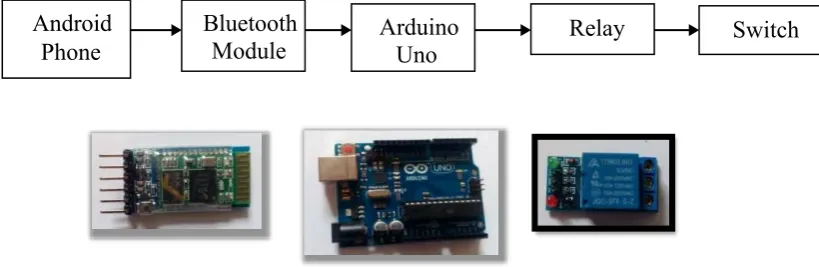
[image:22.595.149.559.558.691.2]3.1 Wireless Switch (WS)
Figure 3.1: Flow Operation for WS
METHODOLOGY
CHAPTER 3
Android
10
3.1.1 Operation for WS
Based on Figure 3.2 above shows that an Android phones send a signal to Bluetooth module. Then Bluetooth module transmits the signal to Arduino UNO in order to control the switch. The 5V of relay is used where the output is connected with socket outlet. Parameter that be used in this experiment is a lamp. From Android phone, it connects with Arduino UNO by using Bluetooth module. In order to control the switch, the 5V of relay is used. This WS is a connector that connect socket outlet with the load. The Bluetooth module, Arduino UNO and relay are the medium transition for this system.
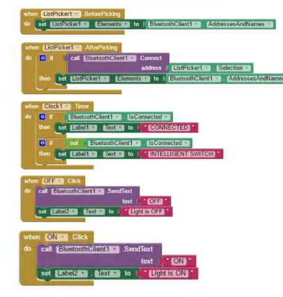
3.2.2 Software Implementation