Full Terms & Conditions of access and use can be found at
http://www.tandfonline.com/action/journalInformation?journalCode=tlcy20
Liquid Crystals Today
ISSN: 1358-314X (Print) 1464-5181 (Online) Journal homepage: http://www.tandfonline.com/loi/tlcy20
The fiftieth anniversary of the liquid crystal display
J. Cliff Jones
To cite this article: J. Cliff Jones (2018) The fiftieth anniversary of the liquid crystal display, Liquid Crystals Today, 27:3, 44-70, DOI: 10.1080/1358314X.2018.1529129
To link to this article: https://doi.org/10.1080/1358314X.2018.1529129
© 2018 The Author(s). Published by Informa UK Limited, trading as Taylor & Francis Group.
Published online: 24 Oct 2018.
Submit your article to this journal
Article views: 27
RCA announcement of the first Liquid Crystal Display on 28th May 1968. Coming exactly eighty years after the report of the first liquid crystal materials, this announcement sparked interest across the globe, and particularly in the UK, Switzerland and Japan. Presentations of the early LCD history from Hilsum, Schadt and Raynes give insights into both the science and also the process of invention itself. These early contributors are followed by a view from the USA from Bos and representation from the companies Sharp and Merck that helped shape the success of these fascinating and useful materials. Also reviewed are talks on the use of organic semiconductors to drive plastic LCD by Sirringhaus, reflective LCD of Folium Optics, retail signage of Displaydata, as well as a look to the future from LCD competitors from Bodle (Phase Change Material displays) and BOE (OLED).
Every revolutionary idea seems to evoke three stages of reaction. They may be summed up by the phrases: First:
“It’s completely impossible – don’t waste my time”; Second: “It’s possible, but it’s not worth doing”; and Third:“I said it was a good idea all along”.
Sir Arthur C. Clarke, (1917–2008)
A record is given of the special symposium organised by the UK & I Chapter of the Society for Information Display to celebrate the fiftieth anniversary of the announcement by RCA of the world’s first liquid crystal display. That statement helped inspire researchers across the world, particularly Cyril Hilsum in the UK, Schadt and Helfrich in Switzerland, and Tomio Wada at Sharp in Japan, to begin researching the application potential of these materials. The symposium was held at the Royal Academy of Engineering in London on 7 June 2018 and included presentations from key players from those early days, including Hilsum and Schadt, but also Peter Raynes, Phil Bos and speakers from both Merck and Sharp. It also included a glance to the future of displays, with talks from Flexenable, Displaydata, BOE, Folium Optics, Bodle Technologies, and an exhibition that included demonstra-tions from BOE, Sharp, Flexenable, Merck and Folium.
The dawn of liquid crystal displays
Some of the technological and scientific predictions observed in Stanley Kubrick’s and Arthur C. Clarke’s
cine-matic masterpiece,2001: A space Odysseyseem accurately prophetic to the modern viewer: a permanently inhabited international space station, videophone communication, processed foods, supercomputers with nascent artificial intelligence and the space shuttle (complete with enter-tainment displays on the seat backrests). On Tuesday, 28 May 1968, the audience watching the film during its Eastern USA premier run at the Loews Capitol Movie Theatre on Broadway in New York will have been as much astonished by these promises of technologies to come as by the story of the influence of a super-advanced alien presence throughout mankind’s history and their purpose in guiding our species to its ultimate goal. One of those technologies on show appeared while astronauts Dave Bowman (Keir Dullea) and Frank Poole (Gary Lockwood) were breakfasting on multi-coloured paste and watching video playback of their BBC 12 interview introduced by an unlikely young-looking 78-year-old Kenneth Kendall, shown on a tablet-like device with a flat-panel display screen. A modern audience, so familiar with twenty-first century liquid crystal displays and the technologies that they allow, may not understand the incredulity of that contemporary viewer witnessing a real glimpse of the future. However, on leaving the cinema that afternoon, and strolling just a third of a mile along West 50thStreet to the Rockefeller Centre on 5th Avenue that same cinema goer may have seen the first evidence that concept would become a reality by 2001. At 5pm in the RCA Headquarters contained within the
CONTACTJ. Cliff Jones j.c.jones@leeds.ac.uk
© 2018 The Author(s). Published by Informa UK Limited, trading as Taylor & Francis Group.
Rockefeller building, RCA Vice President James Hillier and inventors George Heilmeier (1936–2014) and Bernard Lechner (1932–2014) demonstrated the world’s first matrix liquid crystal display (LCD). It utilised the dynamic scattering effects that had been observed by Richard
[image:3.609.120.492.50.280.2]Williams 5 years earlier [1,2] and, as noted by Schadt at the symposium, much earlier work in Europe [3,4]. This demonstration was being made to the world’s press soon after the publication of the first RCA dynamic scattering patent [5] and submission of the forthcoming publication Figure 1.Tuesday, 28 May 1968 in New York: (a) 2001: A space odysseypremiered in NY at the famous loews capitol theatre on 4 April 1968 and was the last movie to be shown there when the theatre closed after almost 50 years on 16 September 1968. (b) A scene from 2001 where tablet computers with flat screen displays are shown, a fact used in 2011 by Samsung when arguing against Apple’s design patent USD 504,889 S1 for the iPad. (c) The 0.3-mile route from the Capitol along West 50thStreet to the RCA Headquarters in the Rockefeller Centre on 5thAvenue (inset). (d) RCA’s George Heilmeier in a publicity shot for the dynamic scattering effect device, with carefully oriented lamp in front of the display to ensure maximum reflectivity near to the specular angle.
[image:3.609.157.455.380.607.2]in the proceedings of the IEEE [6]. Although RCA ceased work on LCD in 1976, when they sold their business to Timex, this announcement had sown a seed that inspired technologists in the UK, Europe and Japan to begin research efforts into LCD that were to create the informa-tion revoluinforma-tion.
At least, this was the idealistic history that I would believe, a romance that led me to suggest fiftieth anni-versary events to the Society for Information Display (SID). Holding an event in London would also give an opportunity to bring together key players from that time around the world to share some of their personal histories of those early days of the LCD. The best start-ing point was to invite Prof. Cyril Hilsum, CBE, FRS, FREng. He was instrumental in the story who, in the late 1960s, responded to an approach made by minister John Stonehouse of the newly formed Ministry of Technology in the UK, who was hoping to deliver what Prime Minister Harold Wilson had called a ‘White Heat’of technological revolution for the UK by initiating a consortium of researchers with George Gray at Hull University, Ben Sturgeon at BDH Chemicals and a team of scientists at the Royal Radar Establishment (RRE) in Malvern, where Hilsum was based.
With Cyril agreeing to talk at the Symposium, it was easier to persuade Martin Schadt, co-inventor of the Twisted Nematic LCD, to make the trip to London
by pioneer Glenn H. Brown in 1965. Of the renowned researchers still active and leading at that institute, Phil Bos has been a keen contributor to the displays world since completing his PhD under the tutelage of Bill Doane at Kent in 1974, inventing the pi-cell while at Tektronics in the early1980s and, on re-joining the institute in 1994, filing over 35 patents on LCD and related devices. Bos would be an ideal representative for the USA. Sharp launched the LCD industry with the release of the first electronic calculator to use an LCD in 1973. Of the companies with a long history of liquid crystals, none compete with Merck, a company that helped Otto Lehman prove that liquid crystal-linity was not due to impurities but a new state of matter in 1904 and has led the world in supply of materials since. These companies were represented by speakers Paul Gass of Sharp Laboratories Europe and Mark Verrall, Senior Vice President of Product Development of Performance Materials.
It was also important to represent the future of displays in the UK, and representatives of the plethora of small-to-medium enterprises working in the field. These were headed by Henning Sirringhaus from Cambridge University, Founder of Plastic Logic and representing Flexenable, who have recently demonstrated curved plastic LCD driven by organic thin film transistors. Guy Bryan-Brown from Display data was to speak about the use of Zenithal Bistable LCD and Electrophoretic displays in retail. John Rudin of Folium Optics presented on the use of Guest Host LCD for niche applications. Philip Yuan of BOE was to show the plans to grow their OLED business and challenge the LCD dominance. Peiman Hosseini pre-sented on the new reflective display being devel-oped at Bodle Technologies using phase change materials.
[image:4.609.72.283.50.331.2]The symposium was enabled by very generous support from our sponsors, Merck, The Institute of Physics, Sharp, BOE, Flexenable, Displaydata and Folium Optics. Not only did that generosity allow us to hold the event at the Royal Academy of Engineering and to provide travelling expenses for Figure 3.Cyril Hilsum presenting on the first 10 years of the
the overseas academic speakers, but also provided for a wine reception for our guests and over 60-strong audience after the event.
Several of the speakers at the symposium ques-tioned whether or not the RCA announcement truly was the beginning of the LCD. Cyril Hilsum pointed out that he had been aware of the RCA work from the early 1960s, following the original work of Williams, and the demonstration by Heilmeier of the first Guest-Host LC effects in 1964. Hilsum suspected something in the ensuing years because the team stopped filing patents and publishing work, a sure sign that RCA management had engaged in a serious project to make room temperature materials, understand the dynamic scattering mechanism, make LCD demonstra-tors suited for watches, clocks and numeric indicademonstra-tors, and show the potential of the technology to meet Sarnoff’s vision and make a flat panel TV display. RCA had already begun to seek licences for the technology from Japanese and European electronic firms before that announcement was made [8]. Indeed, my perso-nal interest in liquid crystals was sparked after finding a wonderful 1964 article by Jim Fergason of Westinghouse in my father’s back issues of Scientific American, which used encapsulated cholesteric in a variety of temperature and pressure sensors [7]. Looking further back, the UK’s Marconi company had filed for a patent based on LC electro-optic effects as early as 1936 [9]. Surely, these portents held equal claim as the start of the age of the LCD? It was Phil Bos, in the opening thesis of his presentation who defined why this event was apposite. The dawn of LCD was actually initiated by the efforts of Hilsum and Schadt at the end of the 1960s and in 1970, and that the celebration was to have the two great men speak-ing at this same event.
Hilsum: the liquid crystal revolution: the first 10 years
Cyril Hilsum is almost as remarkable an orator as he is a scientist. All who commented on the talks that day remarked that the highlight was undoubtedly to hear Hilsum give his personal account of the first 10 years of the LCD age. The world in which his story began seemed just as alien to a twenty-first century audience, as the twenty-first century of 2001 A Space Odyssey seemed to the 1968 cinema-goer. The electronics world was dominated by large industrial players. In the USA, there were AT&T’s Bell Labs at Murray Hill, IBM at Yorktown Heights, GE in Schenectady and Syracuse, MIT’s Lincoln Labs, HP in Palo Alto, Westinghouse, RCA in Princeton and Xerox in Webster
and Palo Alto. In the UK, there were GEC in Wembley, AEI in Manchester, Plessey at Caswell, Marconi in Chelmsford, STL in Harlow, Philips in Redhill and Racal in Reading. In Europe, there were Siemens in Erlangen and Munich, Philips in Eindhoven, Thomson CSF in Paris, CNET in Paris, the Lebedev Institute in Moscow and the Joffe Institute in Leningrad. In Japan, there were Sony, Toshiba, Sharp, Hitachi, Matsushita and Canon. Where things differed from today was the degree of government guidance. Whether through con-tacts with the US DoD, Plan-Calcul in France, MITI in Japan, or MoD CVD, administered through its research arm at RRE/RSRE in Malvern, technological strategy was seen as an area of national importance to the govern-ments of the time. Hilsum also noted that many of the companies would communicate openly with each other, such as in the UK Displays Consortium: ‘we were up against the limits of engineering rather than each other’.
Such government intervention had a direct impact on Hilsum. In March of 1967, the Minister for Technology John Stonehouse visited RRE in Malvern, where Hilsum was the Chief Scientific Officer at the time. Colour TV was beginning to take off across the world, and the UK was already paying enormous royalties to RCA for licences for use of the CRT shadow mask. Stonehouse was incensed by this and asked RRE to start a programme on develop-ing a flat panel alternative when he had returned to London the next day. Hilsum mused that, on a return trip to RRE, Stonehouse reported that the UK paid more in royalties for colour TV than it did on the development of Concorde. When Hilsum asked where he had found this from, Stonehouse replied.‘Why, it was from you’.
The choice of LCD was neither obvious nor immedi-ate. Hilsum recruited six scientists from RRE to form a Working Party and review the options, with input from the UK and US industry and help from CVD and the MoD patents office. The options included solid electrochro-mics from American Cyanamid; liquid electrochroelectrochro-mics from ICI, Philips and IBM; Sharp’s AC electroluminescence and DC electroluminescence from GEC and Phosphor Products; Electrophoretics from Xerox and Plessey; Ferroelectrics from Sandia and BTL, and Liquid Crystals from RCA. In August 1968, when answering a query from the MoD Patents, Hilsum wrote ‘I may say, we are not optimistic about liquid crystals. I would be surprised if the Working Party recommends that work should be started’. Far more promising is seemed to be electro-phoretic effect, which was an early front runner.
indicated a late change to the choice (seeFigure 4) but remained vague about what had driven him to make this last-minute change. However, the result was clear and Hilsum set up a team headed by John Kirton that was soon to recruit new Cambridge doctorate Peter Raynes in early 1970. He also created a Materials Consortium, consisting of RRE, BDH Chemicals and Hull University Chemistry Department that targeted, and of course succeeded, in producing the world’s first wide temperature range liquid crystals centred on ambient temperatures that would be sufficiently stable for use in commercial products.
Hilsum left the essential work done in the next few years to Peter Raynes to describe, moving on to the other breakthrough made in this period: the demonstration of amorphous silicon TFT driving of an LCD panel.
With RCA being the original inventors of the thin-film-transistor [10], the original team working on dynamic scat-tering knew that multiplexing a complex display would require non-linear elements. In 1973, Westinghouse’s Brody et al. [11] demonstrated a 120 × 120 TN LCD based
on CdSE TFT. Hilsum knew that CdS and CdSe semiconduc-tors quickly deteriorated and would not pass lifetime tests. Silicon was unsuitable because it gave a polycrystalline mess when vacuum deposited onto glass. So, the TFT approach seemed gravely flawed and technologists sought alternative means for increasing the non-linearity of the LCD, such as seeking display modes that were inherently bi-stable.
[image:6.609.115.496.54.138.2] [image:6.609.155.457.189.404.2]Development Corporation, the UK government body responsible for taking technology from the public to the private sector:
What are possible applications of extrinsic amorphous semiconductors? Before attempting to give an answer, it is worth stressing that my colleagues and I are physicists interested in the more basic solid-state problems, but without much experience in the device field.
Hilsum’s response in December 1975, copied to Spear stated:
I would certainly think that two potential fields of applica-tion are in displays and solar cells. The need for intra-panel components in displays has been obvious for some years and one wonders whether it would be possible to make a thin film transistor from amorphous silicon.
Spear was positive about the suggestion, writing in January 1976:
In your letter you ask about the possibility of a thin film transistor. In principle the preparation technique allows one to put down any sequence of p and n layers, simply by turning a tap. It seems worth trying in the near future.
It actually took until November 1978 for Spear and Le Comber to send Hilsum an insulating-gate field effect transistor (IGFET) remarkably similar in design to those still used today. The MoD Intellectual Property Department was expert in protecting the inventions coming from both RSRE and its collaborators in the area of liquid crystals, as evinced from the successful control over exploitation of the cyano-biphenyls earlier that decade. They took a meticulous look at whether Spear and Le Combers’ progress could be filed as a patent. However, there had been several filings from RCA and Westinghouse in the mid 1970s. These included a rather non-specific patent from RCA in 1976 [14] that did not narrow the claim to a particular semiconductor for forming the TFT, and a series of patents from the Westinghouse team, mainly on the use of TFT for driving electro-luminescent panels (favoured by Brody) but also including LCD [15]. It was decided that a patent would not be defendable, some-thing that Hilsum still believes true. In February 1979, Spear and Le Comber submitted a brief paper on the characteristics of theirα-Si [16], publishing the sugges-tion of use as the non-linear element in an LCD, and comparing the properties achieved with the require-ments listed by Westinghouse in ref [11]. Twelve months later, Tony Hughes at RSRE had built the world’s first α-Si TFT-driven LCD using the University of Dundee backplane [17]; the age of the LCD had shifted gear.
Earlier this year, Hilsum was present at the unveil-ing of a plaque at the University of Dundee on behalf of the Institute of Electrical and Electronics Engineers that recognised the huge contribution made by Spears and Le Comber to the world of displays. Concluding his talk at the RAE, Hilsum noted that the real pioneers of LCD today were George Gray and Peter Raynes for providing wide temperature stable materials; Martin Schadt and Wolfgang Helfrich for the invention of the Twisted Nematic electro-optic mode; and Walter Spear and Peter Le Comber for the invention of α-Si TFT that enabled complex panels to be made. He also acknowledged the minister, John Stonehouse, who started it all. However, he declined to mention the subsequent history of that mercurial character: the allegations of being a Czechoslovakian spy and subsequent faking of his own death by disappearing from a Miami beach in 1974, only to be rediscovered alive a month later in Australia.
Later in the day, Phil Bos began his presentation with the thesis that the roles played in the invention of LCD by Martin Schadt and Cyril Hilsum were what should be celebrated. He pointed out that the production of stable liquid crystal materials was the fundamental invention that enabled the LCD revolution. Prior to this, unstable LC formed using the Schiff’s bases required glass cells to be frit sealed by heating the substrates to the very high temperatures. This prevented polymer alignment layers to be used, condemning early devices to evaporated inorganic alignment layers, and the associated problems of uniformity and limitations of size. With mixtures such as E7 developed by Raynes at RSRE, not only could devices operate from below−5°C to over +50°C, last many years without breaking down, but also enabled simple rubbed polymer alignment layers and adhesives to be used in the construction too. Moreover, he highlighted not just the importance of material work but also a series of device inventions done at RSRE over the years, referring to papers on field sequential colour [18], the supertwist nematic [19], ferroelectric liquid crystals [20] and the ZBD bistable nematic [21]. All of this achievement arose from the group that Hilsum had founded.
The other great inventor who began the revolution was Schadt, who was to deliver the following talk.
Schadt: from dynamic scattering to field effect displays
through the following decades and is still important today.
At the time of the RCA announcement, Schadt was working on a precursor to organic light emitting diodes (OLED), looking at the electronic and electrolumines-cent properties of crystalline anthracene [22,23]. He moved to work on flat panel displays at Hoffman La Roche in early 1970. In March of that year, Frank Leslie
[image:8.609.115.494.51.511.2]so the disillusioned Helfrich joined Schadt at Hoffman La Roche in October 1970. Schadt realised the brilliance of the idea and began to work on turning it into a practical invention. The two inventors were also familiar with Mauguin’s 1911 paper [25] on the optics of such a twisted structure when formed in a nematic aligned by rubbed plates when the substrates are twisted through 90°. Schadt worked with Boller et al. to make the neces-sary positive dielectric anisotropy nematic PEBAP, made a rudimental rubbing machine (seeFigure 6(b)) and put together the first TN device in late 1970. The first paper was published just days after filing the swiss patent in December 1970. Although that other great LCD inven-tor James Fergason was also to file a similar invention in the USA some months later (illustrating how essential it is to patent and publish as soon as one can) Schadt and Helfrich had the first filing and can justly claim to be the inventors. Notably, the TN mode used a number of firsts for a liquid crystal display device. It was the first use of dielectric anisotropy to switch the liquid crystal from a surface stabilised state; it used polarisers to give the optical contrast and included a rubbed polymer align-ment to give an aligned quiescent state.
While Sharp was beginning to commercialise a cal-culator based on the Dynamic Scattering mode, Schadt explored licencing the TN with Seiko Instruments (see
Figure 6(c)). The TN invention was the first device to use many of the standard elements of a modern LCD, and the first to meet most of the requirements for commer-cial success. The key element was a liquid crystal mate-rial that had suitable birefringence, be colourless, had a high positive dielectric anisotropy, a low viscosity, a wide nematic temperature range and was sufficiently stable to meet a 5-year minimum lifetime for the device. After initiating the market with some less than ideal materials, Seiko moved to the cyano-bipheyls from Hull/RSRE and BDH in 1974. It was about this time that Martin Schadt and Cyril Hilsum first became acquainted. After some initial reticence (see cartoon in
Figure 6(d)), Seiko’s watches begun to take off. As we learnt from Paul Gass later in the day, Sharp were quick to follow suit and switch to the TN mode for their calculators.
Schadt’s interest in liquid crystal materials continued throughout the 1980s. It was clear that the elastic con-stants played a decisive role in the shape of the electro-optic curves, and the inherent multiplexibility. This was true for both the TN and Supertwist (STN) modes, although each had opposite requirements for the ratio of bend and splay elastic constants: low K33/K11for TN
and high K33/K11for STN. Ingeniously, Schadt looked to
the flexible end chain the mesogen, which had conven-tionally been either alkyl or alkoxy. In 1985, he and the
team at Hoffman La Roche discovered that the elastic constants could be controlled through sagacious design of the end chain, by including an alkenyl group in either an even position for low K33/K11or an
odd position for high. Together with the improvements of the mesogenic core material, made largely at Merck, this provided materials that had improved fourfold over only 15 years (Figure 6(e)).
By the early 1990s TFT-based TN were beginning to be exploited in full colour monitor displays, as evinced by Schadt’s photographs of a 1991 model from Hitachi and a 1993 display from LG. By this time, the main technical limitations for monitor applications were the limited viewing angle. Numerous solutions were being explored, including in-plane-switching and multi-domain vertically aligned nematic. In 1991, Gibbons et al. published an article on adding dyes to alignment layers that gave switchable surface orientation with polarised light [26], due to the increased absorption of those dye molecules-oriented parallel to the polarisa-tion direcpolarisa-tion [27]. In 1992, Schadt and Chigrinov patented [28] and published [29] photoalignment based on the polymerisation reaction of a poly-vinyl-4-methoxycinnamate photopolymer under polarised UV. Unlike the dyed polymers, these layers gave permanent alignment to the LC in a direction parallel to the polar-isation. This enabled pretilt to be induced using oblique incidence of the UV light. Throughout the 1990s, photoalignment was used to produce multi-domain alignment to compensate for off-axis viewing, thereby provide two or more domains with opposite sense of tilt. In 1996, the photoalignment was used in dual-domain TN [30] but the most successful mode was multi-domain Vertical Alignment Nematic Mode (MVAN) [30] that was used in Sharp’sAquosLED backlit TV from 2009.
It was inspiring to the symposium audience to hear from Schadt himself the inventions that not only launched the LCD industry in 1970, but also those that allowed the first application of LCD in TV. Those interested in the details of Schadt’s presentation should refer to ref [31].
Raynes: from invention to exploitation
The third of the great inventors to speak at the event was Peter Raynes. In April 1971 and soon after complet-ing his PhD on superconductivity at Cambridge, Raynes moved to Hilsum’s nascent displays group at RRE, join-ing John Kirton, Jenny Constant, Roger Skinner and Anne Ashcroft.
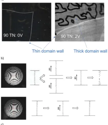
found that maintaining the required alignment free from domains was not automatic. Raynes quickly rea-lised that if the rubbing directions were orthogonal then the twist could be degenerate; either left-handed or right-handed randomly across the sample. Those not so careful to achieve 90° angles between the rubbing
[image:10.609.116.492.61.495.2]gave the material sufficient natural twist to prefer one handedness of twist sense, thereby removing the unwanted reverse twist domains. Although this gave a defect-free quiescent state, Raynes observed that some-times he would still get domains but only after he had switched it to the ON-state. Resolving this took some more careful observations, as shown in Figure 7(a). Here, an undoped nematic with 90° twist is shown to give two senses of twist separated by thin domain walls. Raynes observed that applying a switching field led to much thicker domain walls forming, but only on one side of the region delineated by the thin domain walls [32]; that is, for only one sign of twist. Raynes solved this issue in a characteristic way, first by recog-nising that the symmetry of the system had to be broken and, therefore, there must be a pretilt to the alignment that had not been recognised previously. Second, by simplifying the problem to only the essen-tial elements. His approach, illustrated in Figure 7(b), was to consider what would happen in a cell without twist but different directions of pretilt on the opposing surfaces. Where the cell is anti-parallel, there is no splay-bend in the quiescent state and the tilt is uniform throughout the cell. On application of the field, the director begins to increase its tilt at the cell centre in the same direction to that stabilised by the surfaces. Increasing the field pushes the regions of splay-bend towards the surfaces, and on removal of the field the elastic distortion returns continuously to the original surface condition. However, in a parallel cell, the situa-tion is more complicated. The central director has no tilt in the quiescent state, and a region of high splay-bend must occur in either half of the cell as the field is applied. The twist elastic constant is much lower than either the splay or bend, and hence a region of 180° twist forms at that surface region to relieve the splay-bend distortion. When the field is removed, this reverse twist is retained. For a 90° TN device, the tilt remains constant throughout the cell for one arrangement, but reverses tilt sense when the opposite surface tilts are chosen. Application of the field for the first case causes a uniform increase in tilt throughout the cell, whereas in the latter case causes a region of high splay-bend at one of the surfaces that is relieved by undergoing the less elastically costly twist. For a twisted nematic, this twist would be in the opposite direction to the original twist: that is, if the first state has a +90° twist, the latter will be at−90°, andvice versa. To prove his idea that the rubbed polymer material must have some hitherto unknown pretilt, Raynes did conoscopic measurements on parallel and antiparallel cells (with a high cell gap to give good conoscopic figures). These showed a sym-metric pattern when oriented parallel (thereby
indicating that the tilt was zero at the cell centre and anti-symmetric in the two halves) but shifted by an angle that corresponded to about 2° tilt for the anti-parallel case (Figure 7(b)). Hence, Raynes solved the reverse twist and tilt direction by adding a small amount of cholesteric with a known handedness to the nematic mixture and matching the directions of the pre-tilted surfaces to maximise the tilt of the quies-cent state [33].
Forty-five years later, on the return home from the Symposium, one of my brighter students questioned whether this proof that the polymer had a small pretilt and the reason that the correct arrangement removed reverse tilt were obvious. I remember when I first started studying LCD in the early 1980s working with Raynes think-ing exactly the same thoughts about the TN invention itself. Indeed, later it was suggested to me that the ZBD invention was similarly obvious, given the state of the prior art at the time. As one's career progresses, one is often faced with seemingly intractable problems that as soon as that flash of inspiration has come, the problem seems thereafter trivial. Indeed, often to solve the problem, one has had to simplify it to some appropriate level that only those with the dee-pest understanding could make. Then, in explaining the solution with clarity, by definition the invention is under-stood and seems obvious. As is often said, that is a hallmark of great inventions and was true of many of the inventions described throughout this retrospective symposium.
final mixtures were likely to require three or four compo-nents at least to give the required properties. A method for screening mixtures more quickly was needed. Raynes noted that the logarithm of solubility of one component in another was linear with temperature, albeit with coeffi-cients strongly dependent on the host material [36]. At the eutectic combination, the sum of the solubilities must equate to 100%. For multiple components, the temperature dependence of the solubilities of each was found for a starting mixture defined by the Schröder-van Laar equation. Extrapolating to the concentration where the sum adds to 100% gives both the eutectic composition and the approx-imate melting temperature of that mixture.
Not only was it important to achieve the −10°C to +60°C nematic temperature range target, but it needed to be done with low viscosity and high dielectric aniso-tropy. Of the six low viscosity components, Raynes selected 5CB and 7CB. He knew he could add small concentrations of highly viscous components because viscosity scales with the logarithm of concentration. Thus, he could use one of the twelve components with high clearing points, choosing the pentyl cyano-terphenyl. Finally, he needed a compound that would decrease the melting point dramatically. Raynes knew that this required a different flexible end chain and so selected the octyloxy cyano-biphenyl. The solubility for these four compounds is shown inFigure 8, where the linear plots indicate the eutectic composition for the famous mixture E7. The clearing point of the mixture is approximately linear with concentration and hence about 60°C, whereas the freezing point was estimated to be about −13°C from Raynes’s analysis. Due to this brilliant deductive work, Raynes had produced a num-ber of mixtures used in many commercial devices for several decades, giving BDH Chemicals the commercial advantage in the rapidly growing LCD market. The combined work of the Hull invention, RSRE mixtures
and BDH commercialisation received the Queen’s Award for Technological Achievement in 1979.
Throughout the 1980s, the success of the TFT for pro-viding high levels of LCD multiplexibility was far from assured. Along with a team including Jenny Constant, Bob Smith and Madeline Bradshaw, Raynes investigated the relationship among elasticity, chemical structure and display multiplexing. A first solution was to increase the TN steepness, thereby increase the number of lines that could be addressed in a passive matrix. This could be achieved using a low K33/K11elastic ratio. The RSRE team
found that low K33/K11occurred for hybrid mixtures of the
cyanobiphenyls with dialkyl phenyl benzoates. Again, BDH found ways to produce commercial mixtures, and BDH/RSRE was awarded a second Queen’s Award for Technological Achievement in 1992. The second approach was to increase the twist in the device by increasing the twist angle. Aftergut and Cole had noticed that the TN relaxation time from ON to OFF could be decreased by increasing the cholesteric content of the nematic so that the LC pitch,P, that was shorter than that required to match the natural twist defined by the cell anchoring directions; that is, 0.25 <d/P< 0.5 for a 90° TN cell [37]. This set Raynes and Colin Waters to investi-gate the properties of higher twist anglesФby lowering the pitch still further:
[
2π 1 4
d
P
[
2πþ 1
4 (1)
[image:12.609.125.484.52.198.2]the STN was the display technology that enabled the first liquid crystal monitors and cellular phones.
Raynes ended his presentation with thanks to his colleagues at RSRE, picking out key names from photo-graphs celebrating the 1979 and 1992 Queen’s Awards, as shown inFigure 9.
Gass and Verrall: the (r)evolution of liquid crystals
Two companies with the longest of histories of activity in LCD are Sharp and Merck. The Japanese giant was represented by Paul Gass from Sharp Laboratories of
Europe (SLE). He described both the history of LCD within Sharp, paying particular emphasis to the devel-opments done in the UK at SLE.
[image:13.609.128.486.276.481.2]STN products, first in Scheffer and Nehring’s White on Blue mode, but later with dual-panel compensation and then film compensation to allow for B&W and basic colour panels. In 1988, Sharp launched the world’s first full colour TFT-driven TN targeted directly to com-pete with CRT for TV application. In the 1990s, Sharp released panels using Multidomain Vertically Aligned Nematic to improve viewing angle. First, this used the combined effect of slits in the electrodes and compli-mentary dielectric protrusions, Figure 10(a)). Panels continued to improve into the new millennium with improved aperture ratio MVA made possible using photoalignment.
Sharp’s success relies heavily on combining inno-vation and investment. Gass showed the historical investment in fabrication plants, from the Gen 4.5 line at Mie in 1995, through the Gen 6 at Kameyama in 2004, Gen 8 also at Kameyama in 2006 and finally, the Gen 10 factory at Sakai. This plant is still the largest in the world, using 2850 mm × 3050 mm glass plates to produce eight 65” diagonal TV panels. Moving forward, Sharp remains committed to 8k TV, making not just the LCD panels but also broadcast receivers and cameras to help establish the ecosystem. Sharp has developed a 2.53” diagonal LC on Silicon device for Virtual Reality applications, utilising a novel panel design that switches at twice the speed of a conventional LCD for greater realism.
At the heart of Sharp’s display technology is the Indium Gallium Zinc Oxide (IGZO) semiconductor back-plane, mastered by the company. Not only is the mobi-lity substantially higher thanα-Si, allowing smaller TFT for lower power and higher resolution panels, but the
leakage current is much lower than polycrystalline Si, allowing much lower update rates and hence lower power consumption when pixels do not change from frame to frame. The IGZO backplane is suitable regard-less of the display medium, including LCD, OLED, QD or micro-LED. The inclusion of on-glass IGZO drivers allows a greater range of display form factors for enhanced style and function.
At the exhibition during the lunchtime, Gass demon-strated the latest ultra-low reflectivity panels recently announced at the 2018 Display Week in Los Angeles. These panels include antireflection films that reduce the ambient reflections from 5.7% to 0.3%, thereby allow the panels to be observed in bright sunlight.
[image:14.609.119.491.49.235.2]reached 194 square kilometres of glass in 2017 and is set to grow to 238 km2by 2025, (Figure 11), Merck certainly have picked a winning technology. Throughout the past 50 years, they have continued to innovate with a series of inventions, collaborations and clever acquisitions: the phenyl-cyclohexanes in 1976; the In-Plane-Switching mode patent from the Fraunhofer Institute in 1994; poly-mer stabilised MVA with Sharp in 2006 and ultra-bright Fringe Field Switching mode in 2015. Verrall highlighted Merck’s recent invention of self-aligned VA LCD, where alignment layers can be removed from the cell to give simpler construction and improved dark state and contrast.
Some had questioned whether or not the RCA announcement was the best candidate for the begin-ning of the LCD age. However, Verrall cleverly pointed out that 2018 also represented the 350thanniversary for Merck and the 130th anniversary of the discovery of liquid crystals themselves.
Bos, Sirringhaus and Rudin: latest developments in LCD
Phil Bos of Kent State University has a long career of device-related research, having done his PhD with Bill Doane at Kent in 1978, before joining Tektronix, where he famously invented the π-cell. He returned to the Liquid Crystal Institute at KSU in 1994, where his out-puts have covered all aspects of LC devices, both dis-play and non-disdis-play applications, ranging from field-sequential colour, photo and other novel alignment methods, phase modulators and Fabry-Perot filters, to
[image:15.609.125.482.54.259.2]elegant solution that combines low weight with low cost.
Much of Bos’s presentation focused on recent work on switchable liquid crystal lenses. He began by describing the construction and operation of a 20-mm diameter LC-Graded Refractive Index (GRIN) lens that used variable electric fields to produce the required phase profile. The lenses were formed from a series of concentric circular electrodes with decreasing widths to form a Fresnel structure. Obtaining a suitably analogue (and hence high efficiency) Fresnel lens required a con-stant variation of phase across the lens, and hence over 200 circular electrodes is required. Rather than have 200 separate connections, Bos described how each elec-trode was interconnected to the next using a resistive via, causing a small voltage drop from each electrode to its neighbours, thereby reducing the number of bus lines required to only eight, Figure 12(c). Bos derived a simple expression for the optical path lens of the lens of radius r, given by:
1 f ¼
2Δn:d
r2 (2)
where f is the focal length. Given that stable LC materials are limited to Δn ≈ 0.26, achieving an optical
strength of 1/f= 2D(such as that required to cure presby-opia in optometry) with a typical cell gap of 5μm requires a 7-mm diameter lens. However, if a 20-mm diameter lens is required, then the same optical power would require a cell gap of 400 mm, which is too great to give reliable surface alignment. Moreover, the elastically driven OFF time for an LC device lens is related to the square of the cell gap through the Jakeman–Raynes equation [44]:
τOFF¼γ1:d2
K (3)
where g1 is the twist viscosity andKthe effective elastic constant leading to the response time for a LC lens of this type:
τOFF¼ γ1:r4
[image:16.609.124.482.59.348.2]explanation of these was simple, though he admitted that the rather special properties that resulted were intuitively a little more difficult to grasp.
[image:17.609.105.505.56.290.2]The structure of a Pancharatnam prism is shown in
Figure 13. It is formed from a bi-refringent material in which the optic axis twists linearly across the device plane to form a grating of half-pitchΛ. The thickness of the bi-refringent layer is set to the half-wave plate condition for the wavelength of light,λ. When incident with circular polarised light then at each point on the grating the light is converted to the orthogonal circu-larly polarised state, but with a phase factor of twice the twist angle of the optic axis β. That is, for circularly polarised input light, given by the Jones Matrix:
Ex
Ey IN¼ 1
i
Ex (5)
the polarisation state of the output light is: Ex
Ey OUT¼
cosβ sinβ sinβ cosβ
1 0
0 eiΔn:d
λ
cosβ sinβ sinβ cosβ 1 i Ex
¼cos πΔn:d
2λ
i:sin πΔn:d
2λ
ei:2β 1 i
Ex
(6)
If the retardation is set to the half wave plate condition this gives:
Ex
Ey OUT¼ i:e
i:2β 1
i
Ex (7)
That is, the phase difference between two points on the grating separated by x is simply 2β(x),Figure 13(b). It is continuously increasing, as with a normal prism, but with constant thickness. By swapping the handedness of the incident circularly polarised light, the slope of the phase difference is inverted and so the focus swaps from posi-tive to negaposi-tive, from convergent to divergent,
Bos and co-workers have used the fabrication meth-ods devised by Kim et al. [45], to make lenses with spherical wavefronts, wherein the required pattern is written into a photoalignment layer by interfering plane and spherical waves,Figure 13(c). The lens is then made by creating a LC cell with two such surfaces coaxially aligned and spaced at the half-wave plate condition. After filling with reactive mesogen and curing, the phase difference of the resulting lens is then parabolic, given by:
βð Þ ¼x π:r 2
2λ:f (9)
Figure 13(d) shows the image formed by one of Bos’s Pancharatnam lenses, where the magnification could be switched between x2 and x ½ simply by swapping the sign of the polarisation.
drew attention to the work being done at Leeds University in the UK [46]. Here, a simple meniscus lens is being used to provide the +2.0D correction required for the correction of presbyopia, the malady that affects everyone as they pass 50 years of age, caused by stif-fening of the lens material. Contact lenses have an active diameter of typically 8mm and are readily within the time constraints that Bos had described using Equation (2). Of course, achieving miniaturisation of the associated electronic components for driving and triggering the lens is a major hurdle, but Bos also high-lighted the need for polarisation independent lens. The usual approach is to use two orthogonal active ele-ments in series. Methods such as the use of nano-PDLC and blue-phases are prohibited because of the high voltages and low bi-refringence that they exhibit. Perhaps, postulated Bos, the answer would lie in novel liquid crystal phases, such as the dark conglomerate phase formed by some bent-core liquid crystals. Again, focussing on work done by the Leeds team [47], he pointed out that these phases are inherently isotropic, yet exhibit a field-induced change in refrac-tive index. The induced optic axis of the material is parallel to the applied field and hence remains effec-tively optically isotropic in the lens geometry. Although currently also requiring high fields and temperatures,
the effect is very novel, and material advances could yet provide a practical solution.
[image:18.609.125.485.51.330.2]Henning Sirringhaus from Cambridge University founded the company Plastic Logic in 2000. He now sits on the Board of its daughter company Flexenable, who have recently produced the world’s first organic thin film Field Effect Transistor-driven LCD, or OLCD,Figure 14(b). For over 30 years, the mobility of small molecule and conjugated polymer organic materials has steadily increased [48] with new materials and improvements in the understanding of molecular packing, Figure 14(c), allowing a hundredfold increase in the past decade alone [49]. At the beginning of that period, OTFT were suited for simple applications, such as sensors and driving electro-phoretic panels. However, with the advent of higher mobi-lity organic semiconductors that can be processed uniformly, at low cost and with the necessary reproduci-bility and stareproduci-bility, OTFT are suited for driving more com-plex systems, such as full colour in-plane-switching LCD. Unlike other TFT,Figure 14(d), the OTFT can be processed below 100°C, at high yield and on flexible substrates. This makes them highly competitive for conformal and flexible display applications, and Flexenable has recently announced a licence deal with Chinese LCD manufacturer Truly to target automotive and consumer electronics appli-cations with their plastic displays.
Particularly important is that the materials can be solution processed uniformly, and with the required mechanical stability. Although fused-ring small mole-cules such as pentacene readily achieve mobilities between 1 and 10 cm2/Vs due to their high degree of delocalisedπ-electrons, this is rarely achieved uniformly across spun-coat films, due to variations in the degree of polycrystallinity. Solution processing is greatly helped by substituting the electron-rich groups onto a tri-isopropyl-silylethynyl group to form the derivative TIPS-P, as shown in Figure 15(a). A high mobility is obtained from spin coating since the material has a high degree of crystallinity, wherein the pentacene groups form a 2D brick-wall structure [50] with co-facial packing that gives a high degree ofπ–πorbital overlap,
Figure 15(b).
Sirringhaus also reported progress on high mobility, low band-gap polymer-based semiconductors. Mobilities over 3 cm2/Vs have been achieved in donor-acceptor co-polymers such as indacenodithiophene–benzothiadiazole (IDT-BT) due to the structure of alternating electron rich and electron deficient units, Figure 15(a). Although of high mobility and readily processed with a high degree of uniformity, degradation occurs due to water trapped within nanometre-sized voids in the polymer microstruc-ture. Molecular additives such as Tetracyano-quinodi-methane (TCNQ) displace the water raising the change in threshold voltage after 25 h of electrical driving from
ΔVT > 6V to significantly less than the target level of
ΔVT= 1V.
After depositing the active backplane onto a flexible TAC film,Figure 15(c), the correct cell gap is maintained using a polymer wall structures that seal the cell to the front film with printed colour filters. Uniform illumination is obtained using a bespoke LED array with a small airgap between the source and LCD. The 1280 × 720 cylindrical 12.1”diagonal OLCD demonstrator shown inFigure 14(b) has a 60 mm radius of curvature. The display was shown at the exhibition associated with the anniversary event and was impressive indeed. Perhaps, flexible, or at least con-formal LCD, are close to completing their long gestation. With the proliferation of market ideas presented, from wearable displays, smart watches, foldable smartphones, multi-function smart cards to coffee vending machines and conformal automotive displays, perhaps, this time it will be a market pull more than a technology push.
[image:19.609.141.464.53.289.2]against each other simply by adjusting the amount of dye doping. Obviously, it is essential to use dyes with the highest dichroic ratios and S order parameter when doped into the nematic host. Rudin emphasised that
[image:20.609.130.480.49.362.2]solubility, stability, cost and toxicity were also important factors, and that there were thousands of potential dyes (azo-dyes, perylenes anthraquinones, cyanines, squaranes, rylenes, calixaranes, dithiolenes, Figure 16.John Rudin’s summary of the pros and cons of four different Guest Host mode LCD approaches. The phase change device was chosen by Folium.
[image:20.609.126.484.424.611.2]phthalocyanines, di-imminiums, etc.) and many produ-cers (Nagase/Hayashibara, Nematel, BASF, CSS, Merck) to choose from. He also stressed the importance to opti-mise the LC host and provide high-order parameter combined with low birefringence, high dye solvency with little solvato-chromatism and an insensitivity to chiral doping. Reflective colour displays add a series of difficulties, as is evident from the lack of such devices in the market. First, full colour requires a triple stack, with the subtractive colours Cyan (absorb red), Magenta (absorb green) and Yellow (absorb blue) addressed in separate layers. In addition to transmissive losses caused by the light passing through six electrodes on reflection, this introduces significant parallax and the associated colour leakage. Folium helped avoid this by concentrat-ing on plastic displays in applications that did not require high resolution. Rudin stated that, although obtaining a good black state was relatively easy, good colour separa-tion was much harder. This is illustrated by the typical magenta dye, shown inFigure 17(c), which exhibited too little blue and too much green compared with the ideal. This lack of spectral purity meant that even with dichroic ratios as high as 12 or above, the displays were unsuited for conventional consumer applications, such as mobile phones. White states and contrast ratios are poor and the
modes/cell gaps used prevent the attainment of video frame rates. However, the ability to switch through a broad range of reflective colours, with a wide viewing angle that has a steady fall-off without colour shift, meant that Folium was able to find niche markets where they could offer a big difference over their competitors.
[image:21.609.126.485.54.320.2]Three markets that Folium has targeted so far were detailed. The first is health tags, where a simple, attractive colour label with a high degree of legibility, and long battery life could provide notification of medicine usage. The second market was in combination with a high visi-bility retro-reflector. The illustrated use was for cyclists where the addition of simple animation added to the visibility noticeably, something that could be used in both day and night time. For me, the most impressive of demonstrators was an active camouflage system.
switching to a more suitable colour for either environ-ment, c) and d), was most impressive and I should imagine that this would be highly attractive to military customers. Rudin pointed out that Folium are seeking licensees for their technology, something that should be easily man-ageable given the great progress that they have made.
Bryan–Brown, Hosseini and Yuan: beyond the LCD
Reflective displays were also the theme of presenta-tions by Guy Bryan–Brown from Displaydata Ltd, and Peimann Hosseini from Bodle. Neither company now uses LCD but have chosen alternative technologies.
From spinning out of the RSRE display group (or DERA as it had by then become) in 2000 until 2014, Displaydata were known as ZBD Displays Ltd. [51].
The founders had invented a bi-stable LCD based on a deep homeotropic grating layer on one of the internal surfaces of an otherwise standard TN LCD. As Bryan– Brown explained, the technology could be made at low cost similar to STN, by copying an original photolitho-graphically defined master grating onto a film, and using an embossing technique to impart the grating alignment layer at high yield into a standard LCD pro-duction line, Figure 19(a). The electro-optic operating voltages were maintained from master to master by
varying the anchoring energy of the photopolymer used to form the grating. Displaydata produced weak and strong anchoring energy homeotropic photopoly-mers that enabled tuning of the latching voltages over a 100% range.
[image:22.609.110.497.53.297.2]advantage of the Displaydata system is the ability to address either a hypermarket or a simple mobile phone store with a very low-cost infrastructure. Some of these smaller stores have much lower lighting levels to create the ambience that the retailer prefers. Of course, a great advantage of all LCD is the adaptability and in particular the ability to use other optical components to control the light. Bryan–Brown showed some excellent demonstrations, reproduced in Figure 19(b) of the use of a light control film from Lintec that enabled light to be concentrated into the vertical viewing plane, when the illumination con-ditions were diffuse.
With the diminishing E-book reader market and the commoditisation of TFT backplanes, E-ink has been forced to lower costs to tackle new markets. With the shelf-edge label sector forecast to be several billion dollars by 2022, the retail sector is also a natural fit for them. The ZBD cost advantage was further lessened when additional films need to be used. Moreover, retailers were still not happy with sacrificing the horizontal viewing angle when, as shown in Figure 19(b), the Lambertian nature of an EPD panel met their requirements. So, over the past 4 years, Displaydata have begun to market labels that use EPD. Referring to the instance when Apple’s own introduction of the i-Phone killed off the i-Pod market, Bryan–Brown quoted Steve Jobs:‘if you don’t cannibalise yourself, some-one else will’.
Of particular importance to the retailer is the ability to show some colour, usually to highlight a promotion. Rather than use the standard polymer encapsulated EPD that is used in most E-book readers, Displaydata use the
micro-cup EPD previously developed by Sipix, and acquired by E-ink in 2012. Each micro-cup contains three particle types dispersed in a clear fluid; negatively charged black, nega-tively charged coloured (usually red or yellow) and posi-tively charged white particles, Figure 20(a). Switching between the white and black or coloured particles is simply done by reversing the sign of the applied field across the pixel. Discrimination between the like-charged black and coloured particles is done by designing the particles to have different size (mass) and zeta potential (the electro-static repulsion between the particles). Hence, the choice of which colour is visible at the display front plane is depen-dent on the temporal and voltage sequence of the addres-sing pulses. Displaydata retains a strong competitive advantage in this sector. Not only is its solution more robust and low cost than its competitors, the fact that it retains a strong display engineering team within the com-pany allows it to produce the best-looking ESLs.
[image:23.609.121.491.52.286.2]thin layer also minimises optical absorption effects, giving strong interference colours when spaced from the mirror by a sub-wavelength transparent dielectric. The transition is bi-stable, meaning a passive matrix device can be switched line-by-line to form a complex image. Two-colour operation gives a reflectivity of 70%, beating all other current reflective technologies, although the current 4:1 contrast ratio is somewhat low. Very high levels of resolu-tion are possible, only restricted by fabricaresolu-tion and aper-ture ratio limits, and the layers were readily formed on flexible, metallic foil [52].
Hosseini described recent progress to solve some of the original issues with the technology. Notable among these were the difficulties associated with making larger area pixels typical of the display industry. The
Gallium-Antimony-Tellurium (GeTe–Sb2Te3pseudo-binary alloys,
GST) were originally developed for ultra-high-resolution laser discs [53]. Switching pixels larger than 1μm2proved difficult, since the resistivity of the two states is markedly different such that areas in the higher resistance state could not be switched once a current path had formed through the lower resistance state. Thus, it is essential to de-couple the electrical and optical response. This was achieved using the micro-heater design for the electrodes shown in
[image:24.609.137.471.47.496.2]states. However, he also described the rather intriguing shorter-term approach of using the SRD as a switchable colour filter for a B&W reflective device such as an electro-wetting or polariser-free LCD display.
Philip Yuan, VP Sales and marketing from BOE, China presented his company’s vision for the 5G era. This was a fascinating, yet salutary discourse for the largely LCD supporting audience. BOE is ranked number one in the world for LCD panels used for each of mobile phones (23% of the market), tablets (39%), notebooks (31%), monitors (26%) and TV (19%), with multitudinous cus-tomers including Huawei, Samsung, HP, Dell, Sony etc., its vision is firmly focussed on OLED to deliver their 5G future.
The display requirements BOE sees as critical, listed in
Figure 22(b), includes all aspects of what one would expect for a modern display: speed, contrast, viewing angle, colour gamut, resolution. 5G applications such as Internet-of-Things (IoT), autonomous vehicles, wearables, near-eye dis-plays (VR/AR), require a more diverse range of shapes including high degrees of flexibility, foldability and con-formality. However, an important aspect is the integration of sensors with the display, for things like fingerprint recog-nition, light sensing, etc. This is an area where OLEDs have advantage over the LCD, since high brightness/low-power
displays can be formed from pixels with a smaller aperture ratio, thereby allowing additional functional elements to be included with the p-Si electronics at each pixel.
[image:25.609.119.490.51.348.2]no hurry to replace a TV set with a more-expensive equiva-lent. BOE are rightly concentrating on markets where the additional flexibility and functionality are desirable. A user of both an i-Phone and i-Pad would certainly pay premium for a device incorporating the foldable display shown in
Figure 23(b).
Conclusion
[image:26.609.119.491.52.275.2]The sponsors had also arranged for an associated technol-ogy showcase, including historical LC-related artefacts and demonstration of the ultra-high contrast self-aligning LCD from Merck, the active camouflage demonstrators of Folium, Flexenable’s 12”conformal OLCD cylinder, sunlight Figure 23.Video capture snapshots of (a) a fluttering flexible OLED display designed with wearable applications in mind, and (b) a re-foldable OLED tablet from BOE.
[image:26.609.115.494.332.558.2]readable and 3D LCD from Sharp, and some beautiful 4k Digital Picture Frames from BOE,Figure 24.
In his closing remarks, Jones observed that the gen-eration which included Hilsum, Raynes and Schadt was built on the work of earlier greats; other than the RCA team, they included George Gray at Hull, Shunsuke Kobayashi at Tokyo, Glenn Brown at Kent and Jim Fergason at Westinghouse. The day emphasised the intellectual brilliance of these early generations also proved good innovation was being continued by the technologists of this current generation. The audience included a significant number of younger researchers too, promising a bright future for Liquid Crystals and their application. The cause for celebration is not the passage of time, but the great people that have and continue to make the field so vibrant.
This article is dedicated to John Mansell, who dedi-cated many years of service to the UK&I branch of the Society for Information Display, and who sadly passed away shortly after this meeting, in August 2018. The author also wishes to thank the EPSRC for an Advanced Manufacturing Fellowship EP/L015188/2, the UK&I Chapter of SID, and Dr Ben Broughton for organisational help.
Disclosure statement
No potential conflict of interest was reported by the author.
ORCID
J. Cliff Jones http://orcid.org/0000-0002-2310-0800
References
[1] Williams R. Domains in Liquid Crystals. J Chem Phys.
1963;39(2):384–388.
[2] Williams R. U.S. Patent 3,332,485. Priority date Nov. 9.
1967, 1962–1967
[3] Bijörnstal Y. Untersuchungen über anisotrope
Flüssigkeiten. Ann Phys.1918;56:161.
[4] Zwetkoff V. Acta Physicochim U.R.S.S.1937;6:885. [5] Heilmeier GH, Zanoni LA. Electro-optical device” US
patent 3,499,112 A. Priority date 31 Mar 1967,1967. [6] Heilmeier GH, Zanoni LA, Barton LA. Dynamic scattering:
a new electrooptic effect in certain classes of nematic liquid crystals. Proc IEEE.1968;56:1162–1171.
[7] Gross B. How RCA lost the LCD. IEEE Spectr. 2012;49 (11):38–75.
[8] Fergason JL. Liquid Crystals. Sci Am.1964;211(2):76–86. [9] Levin B, Levin N. Improvements in or relating to Light
Valves,”British Patent No. 441 274, issued 1936,1936
[10] Weimer PK. Thin film transistors. In: Wallmark JT, Johnson H, editors. Field effect transistors. Englewood Cliffs: N. J. Prentlce-Hall;1966. p. 216–252.
[11] Brody TP, Asars JA, Dixon GD. A 6 × 6 inch 20 lines-per-inch liquid- crystal display panel. IEEE Trans Elect Dev.
1973Nov;ED-20(11):995–1001.
[12] Spear WE, Le Comber PG. Substitutional doping of amor-phous silicon. Solid State Commun.1975;17:1193–1196. [13] Spear WE, Le Comber PG, Kinmond S, et al. Amorphous
silicon p-n junction. Appl Phys Lett.1976;28(2):105–107. [14] Goodman LA . Liquid Crystal Display with transistors”, US
[image:27.609.142.470.52.298.2][20] Anderson MH, Jones JC, Raynes EP, et al. Optical studies of thin layers of smectic C materials. J Phys D: Appl Phys.
1991;24:338–342.
[21] Wood EL, Bryan-Brown GP, Brett P, et al. Zenithal bistable device (ZBD) suitable for portable applications, Vol. 31. Proceedings of SID; 2000 May 18–22; Long Beach, USA, 124–127.
[22] Schadt M, Williams DF. Low-temperature hole injection and hole trap distribution in anthracene. Chem Phys.
1969J;50(10):4364–4368.
[23] Williams DF, Schadt M. Electroluminescent device with light emitting aromatic, hydrocarbon material”, US Patent 3,621,321; Priority date Oct. 28, 1969,1971. [24] Leslie FM. Some magneto-hydrostatic effects in nematic
liquid crystals. J Phys D: Appl Phys.1970;3:889–897. [25] Mauguin C. Sur les cristaux liquides de Lehmann. Bull Soc
Franc Mineral.1911;34:71–117.
[26] Gibbons WM, Shannon PJ, Sun S, et al. Surface-mediated alignment of nematic liquid crystals with polarized laser light. Nature.1991;351:49–50.
[27] Jones JC, Day SE. Shedding light on alignment. Nature.
1991;351:15.
[28] Chigrinov VG, Kozenkoff VM, Novoseletsky NV, et al.. Process for making photopolymers having varying orien-tation using light to orient and polymerise”, US Patent 5,389,698; Priority date 8th July 1992,1995.
[29] Schadt M, Schmitt K, Kozenkoff VM, et al. Surface-induced parallel alignment of liquid crystals by linearly polymerized photopolymers. Jap J Appl Phys.1992;31(7):2155–2164. [30] Seiberle H, Schadt M. Photo-alignment and patterning of
planar and homeotropic liquid crystal display configura-tions, SID Proc. of 18th Asia Display, 1998, 193. Revised version of paper published in J. SID. 2000;8 (1):67–71. [31] Schadt M. Liquid crystal displays, LC-materials and LPP photo
alignment. Mol Crystals Liquid Crystals.2017;647(1):253–268. [32] Raynes EP. Improved contrast uniformity in twisted nematic liquid-crystal electro-optic display devices. Electron Lett.1974;10(9):141–142.
[33] Raynes EP. Liquid-crystal devices, US Patent 4,084,884. Priority date 21st February 1974,1978.
[34] Gray GW, Harrison KJ. Liquid crystal materials and devices, US Patent 3,947,375. Priority date 9th November 1972,1976.
[40] Katoh K, Endo Y, Akatsuka M, et al. Application of retardation compensation; a new highly multiplexable black-white liquid crystal display with two supertwisted nematic layers. Jpn J Appl Phys.1987;26(11):L1784–L1785.
[41] Love GD, Major JV, Purvis A. Liquid crystal prisms for tip-tilt adaptive optics. Opt Lett.1994;19(15):1170–1172. [42] Collings N, Davey A, Christmas J, et al. The application
and technology of phase-only liquid crystal on silicon devices. J Dis Tech.2011;7(3):112–119.
[43] Johnson KM, McKnight DJ, Underwood I. Smart spatial light modulators using liquid crystals on silicon. IEEE J Quantum Electronics.1993;29(2):699–714.
[44] Jakeman E, Raynes EP. Electro-optic response times in liquid crystals. Phys Lett.1972;39(1):69–70.
[45] Kim J, Li Y, Miskiewicz MN, et al. Fabrication of ideal geometric-phase holograms with arbitrary wavefronts. Optica.2015;2(11):958–964.
[46] Bailey J, Morgan PB, Gleeson HF, et al. Switchable liquid crystal contact lenses for the correction of presbyopia. Crystals.2018;8(1):29.
[47] Milton H, Nagaraj M, Kaur S, et al. Field-induced refrac-tive index variation in the dark conglomerate phase for polarization-independent switchable liquid crystal lenses. Appl Opt.2014;53(31):7278–7284.
[48] Kumar B, Kaushik BK, Negi YS. Organic thin film transis-tors: structures, models, materials, fabrication, and appli-cations: a review. Polymer Rev.2014;54(1):33–111. [49] Harding MJ, Horne IP, Yaglioglu B. Flexible LCDs enabled
by OTFT. SID Dig Tech Pap.2017;53(2):793–796. [50] Sirringhaus H. Organic field-effect transistors: the path
beyond amorphous silicon. Adv Mat.2014;26(9):1319–1335. [51] Jones JC. Defects, flexoelectricity and RF communica-tions: the ZBD story. Liq Cryst.2018;44(12/13):2133–2160. [52] Ríos C, Hosseini P, Taylor RA, et al. Color depth modula-tion and resolumodula-tion in phase-change material nanodis-plays. Adv Mater.2016;28(23):4720–4726.
[53] Yamada N, Ohno E, Akahira N, et al. High speed over-writable phase change optical disk material. Jpn J Appl Phys.1987;26(4):61–66.