This is a repository copy of The Optimum Position of Water Heat Transfer Coils
Downstream of a Radial Swirler in a 20kW Heater.
White Rose Research Online URL for this paper:
http://eprints.whiterose.ac.uk/119953/
Version: Accepted Version
Proceedings Paper:
Andrews, GE orcid.org/0000-0002-8398-1363 and Kim, MN (2017) The Optimum Position
of Water Heat Transfer Coils Downstream of a Radial Swirler in a 20kW Heater. In:
Proceedings of 13th International Conference on Heat Transfer, Fluid Mechanics and
Thermodynamics (HEFAT2017). 13th International Conference on Heat Transfer, Fluid
Mechanics and Thermodynamics (HEFAT2017), 17-19 Jul 2017, Portoroz, Slovenia. , pp.
761-766.
eprints@whiterose.ac.uk https://eprints.whiterose.ac.uk/
Reuse
Unless indicated otherwise, fulltext items are protected by copyright with all rights reserved. The copyright exception in section 29 of the Copyright, Designs and Patents Act 1988 allows the making of a single copy solely for the purpose of non-commercial research or private study within the limits of fair dealing. The publisher or other rights-holder may allow further reproduction and re-use of this version - refer to the White Rose Research Online record for this item. Where records identify the publisher as the copyright holder, users can verify any specific terms of use on the publisher’s website.
Takedown
If you consider content in White Rose Research Online to be in breach of UK law, please notify us by
THE OPTIMUM POSITION OF WATER HEAT TRANSFER COILS DOWNSTREAM
OF A RADIAL SWIRLER IN A 20KW HEATER
Andrews, G.E*. and Kim, M.N. *Author for correspondence
School of Chemical and Process Engineering University of Leeds,
Leeds, LS2 9JT, UK., E-mail: profgeandrews@hotmail.com
ABSTRACT
A 76mm outlet diameter radial swirler with 8mm vane depth was investigated in a 140mm combustor diameter condensing 20 kW ultra-low NOx boiler. Low NOx was achieved using lean well mixed combustion with a 0.7 equivalence ratio (Ø) together with the minimisation of thermal NOx formation by cooling the flame immediately after 99% of the heat release had been achieved. This was shown to be 70mm downstream of the radial swirler outlet. The aim was to show that small turbulent flame combustion systems could be applied, for more compact ultra-low NOx water heaters than current laminar flame heaters. Fuel injection was through the wall of the 76mm outlet throat, which good fuel and air mixing in the downstream swirling shear layer. Fuel and air mixing and a short flame development was assisted by the use of a 41mm diameter outlet orifice at the exit of the wall injector 76mm diameter radial swirler outlet passage. A 4 mb burner pressure loss was used, which is typical of domestic fanned air combustion systems. The air inlet temperature was 400K, which is typical of reverse air flow cooled combustion chambers at domestic water heater conditions. A water cooled heat transfer coil was traversed into the flame to determine how close to the swirler exit the heat transfer could occur, without a major increase in the combustion inefficiency. The strong swirling flow interaction with the heat exchanger coil give an 89% thermal efficiency with the front of the coil 70mm from the swirler outlet. The emissions measurements showed that the combustion inefficiency was below 0.1%, the CO/CO2 ratio <0.001 and the NOx emissions were 5ppm at 0% oxygen with the heat exchanger at 70mm from the radial swirler outlet. This design easily met the 2018 EU legislation for eco-design of domestic water heaters.
INTRODUCTION
In the UK gas fired heating accounts for about 5% of total NOx emissions at 45 kTonnes of NO2 emissions [1, 2]. In New England, USA, NOx from residential heating was 7% of total NOx emissions in 2011 [3]. NOx emissions from boilers are required to be reduced to ultra low NOx emissions in many areas of the World including Europe [4] and the USA [5]. In some areas, operators are required to meet what are called “Ultra-Low NOx” (ULN) boiler requirements, typically less
than 10-12 ppm and as low as 5ppm in some areas [5]. In the
Bay Area of California, boiler NOx emissions for natural gas (NG) are 30ppm for 0.5 – 1.5 MW, 15ppm for 1.5 – 6 MW decreasing to 5ppm for >22 kW boilers [6]. The San Joaquin Valley District of California has water heater NOx regulation for residential properties after Oct. 1st 2018 at 14 g/GJ [7] (compare with EU regulations for biomass boilers of 150 g/GJ). This converts to an emission index (EI) of 0.7 gNOx/kgfuel using a NG CV of 50 MJ/kgfuel.
The EU Ecodesign regulations [4] for small residential gas boilers, requires NOx to be less than 56 mgNOx/kWh from 26th Sept 2018. For natural gas (NG) with a CV of 50 MJ/kg this is 13.9 gNOx/GJ and an emission index of 0.78 gNOX/Kgfuel. This is very similar to the San Joaquin Valley NOx regulation above. An EI of 0.7 g/kg converts to about 27 ppm of NOx corrected to 0% oxygen or 58 mg/Nm3. This is very similar to the Bay Area regulation pf 3-ppm of NOx for 500 kW boilers. The 2018
EU residential boiler NOx regulations are thus similar to the ultra-low NOx emissions regulation in California. The present
work demonstrates a compact residential burner design with ultra-low NOx emissons of 0.17 EI and 5ppm NOx at 0%
oxygen., well inside the range for ultra-low NOx emissions.
Please quote the reference as:
Andrews, G.E. and Kim, M.N., “The Optimum Position of Water Heat Transfer Coils
Downstream of a Radial Swirler in a 20kW Heater”.
ULTRA LOW NOX RADIAL SWIRLER DESIGN
Normally, domestic water heating boilers use laminar flame combustion system with an air driven fan at 4mb pressure loss. Achieving low NOx using this design is difficult, as laminar flames do not have sufficient flame stability to achieve low NOx using very lean combustion. Although, the use of porous tube burners can overcome this problem. Two common methods of NOx reduction with laminar flame burners are: flue gas recirculation and/or heat extract from the flame using solid copper inserts that conduct heat from the flame to the water cooled heat exchanger. The present work demonstrates that at 4mb pressure loss, a compact turbulent flame with high swirl can be used to give a compact low residence time low NOx burner. Combustion noise is proportional to the pressure loss and so at the same pressure loss, excessive noise is not anticipated. However, no combustor noise measurements were made in the present work, but there was no significant combustion noise detected by ear in the tests.
The ultra-low NOx radial swirler design was first
developed for industrial gas turbine applications [8], using radial vane passage fuel injection with lean well mixed combustion. This was also shown to give low NOx emissions for liquid fuels [9]. It was also shown that fuel injection through the radial swirler outlet duct wall [10], also gave good fuel and air mixing with very low NOx emissions, which were as low as those for vane passage injection. This mode of fuel injection was used in the present work, as shown in Fig. 1. The
design of the radial passage was shown [11] not to be of critical importance and the original curved passage design had similar NOx results to rectangular or circular fixed area radial passages. The first industrial application of this low NOx design method [12] used aerodynamic converging passage radial swirlers, which Alkabie et al. [11] had shown to give similar results to the other vane passage designs. The second application of the radial passage fuel injecton design used rectangular radial vane passages, with fuel injection through the passage wall [13]. Since then 6 other industrial gas turbine companies have used radial swirlers with vane passage fuel injection, to achieve ultra-low NOx emissions. Andrews et al. [14] advocated
impingement regenerative cooling of the backside of the combustor with the cooling air flowing into the radial swirler
vane passages. The first industrial application of this concept was by Agbonzikilo et al. [15] using rectangular vane passage fuel injection and impingement backside cooling. This type of impingement regenerative backside cooling has been investigated experimentally and using CFD predictions by El
-Jummaih et al. [16].
The ultra-low NOx radial swirler and combustor design is
shown in Fig. 1. It used 8 curved passage radial swirlers [8] with 8mm vane depth. Fuel injection was via 8 equispaced 3mm holes in the wall of the 76mm diameter radial swirler outlet. The low air flow rates used at the low thermal powers of 20kW boilers was utilized to generate the main pressure loss at the radial swirler exit duct outlet, using a 41mm diameter outlet orifice. This has been shown previously [17] for axial swirlers to give beneficially effects on NOx emissions, as it increased the size of the outer recirculation zone. The distance from the rear wall of the radial swirler and the orifice plate outlet was 60mm and this gave an upstream fuel and air mixing space that led to close to premixed fuel and air low NOx emissions. The flame was ignited using a wall mounted 15J surface discharge ignitor mounted 30mm downstream of the radial swirler orifice outlet plane.
RADIAL SWIRLER AERODYNAMICS
The aerodynamics of the radial swirler were investigated using conventional k- turbulence modelling and the FLUENT
[image:3.612.49.287.367.522.2]CFD code. The results for the axial velocity profiles are shown
[image:3.612.342.546.369.537.2]Figure 3: Predicted turbulence kinetic energy, TKE, m2/s2 for the radial swirler with and without the 76mm diameter passage exit orifice of 41mm diameter.
in Fig. 2 for the radial swirler with and without the outlet orifice. The predictions were carried out at a test condition of 400K with a pressure loss of 4 mb. This give a higher flow velocity without the exit orifice and hence the mean velocity was higher. The mean 140mm diameter combustor velocity with the 41mm exit orifice was 0.85 m/s.
The peak velocity at the exit plane was predicted in Fig. 2 to be 18 m/s with the radial swirler outlet orifice and 13 m/s without the orifice plate. The higher shear velocity with the 41mm outlet orifice produced greater shear and higher kinetic energy of turbulence (TKE), as shown in Fig. 3. The TKE was much more spatially concentrated downstream of the radial swirler passage orifice outlet and the peak TKE was double that without the exit orifice plate. This higher TKE produced better fuel and air mixing and lower NOx emissions.
EXPERIMENTAL TECHNIQUES
The test rig is shown in Fig. 1 and the combustor was 140mm diameter and 330mm long, which was the length used in gas turbine combustor low NOx research. The determination of the minimum length for small 20 kW burner applications was the objective of the present work. The outside wall of the combustor was uncooled other than by natural convection and radiation heat losses.
The water heat exchanger was made of a spiral of 6.3mm OD steel tubing in the form of a coil with a flat end to the coil and ten loops of the coil on a center-line of 120mm diameter.
This placed the water cooled tubes in the outer swirl flow and only the feed-water line passed down the central recirculation
zone of the flame. This heat exchanger was mounted so that it could be traversed towards the radial swirler outlet so as to vary the distance of the flame to the quench region. The water flow rate was determined using a variable area flow meter and the temperature rise determined using Type K mineral insulated thermocouples. This enabled the heat transferred to the water
to be determined in kW. The tests were carried at 20 kW of heat output.
The emissions were measured using a water cooled gas sampler 330mm downstream of the radial swirler outlet orifice and downstream of the heat exchanger coil. The distance to the heat exchanger quench position was variable by moving the whole heat exchanger coil. The mean emissions were obtained using a 40 hole ‘X’ sample probe with holes on centers of equal area, 330mm from the radial swirler orifice outlet plane. The exhaust gases were passed to the gas analysis system via a heated sample line, heated filter and pump so that THC and NOx were measured hot. The gas sample for NDIR CO, CO2 and O2 analysis was passed through a 4oC cooler that achieved gas sample water condensation, so that these gases were measured dry. The measured NOx and THC were converted to a dry basis, as used in small boiler emissions regulations, by corrected after the tests. The gas analysis was used to determine the combustion equivalence ratio by carbon balance.
NOx emissions were measured using a chemiluminescence NOx analyser. This had a converter to convert NO2 into NO and this was used to determine the NO2/NO ratio. CO and CO2 emissions were determined using NDIR and unburned hydrocarbons were determined using a flame ionization detector (FID).
EXPERIMENTAL TEST CONDITIONS
The combustion air was electrically preheated to 400K, as this is representative of the temperature achieved using backside reverse flow cooling of the combustor. Reverse flow cooling of the combustor was not used in the experiments, but it would be used in applications of this ultra-low NOx burner
concept in a domestic water heating boiler.
The air and fuel flow was set to achieve a 0.7 equivalence ratio with an air flow pressure loss of 4mb across the radial swirler and a fuel thermal input of 23.3 kW. This was a heat release rate of 1.5 MW/m2, which is very high for domestic water heaters and as a consequence gives a very compact water heater. The 41mm diameter orifice swirler outlet was designed to achieve 4 mb pressure loss, which is typical of modern fan driven compact residential water heaters. In related work lower pressure losses were investigated, but not in terms of the minimum distance for the heat exchanger location. The 4mb pressure loss generated the highest TKE for fuel and air mixing and flame stabilization. At lower pressure loss the NOx emissions were higher, but the increase was not large.
Lower NOx could be achieved by operating at leaner mixtures with lower adiabatic flame temperatures. Alternatively, power output modulation could be achieved by reducing the fuel flow to reduce the flame temperature. In work for gas turbine applications, using radial swirlers, it has been shown that the lowest NOx combustors use lean well mixed combustion and have NOx emissions of 3 ppm corrected to 15% oxygen at 1900k [18]. This converts to 10 ppm at 0% oxygen and the present work will show NOx emissions of 5ppm at 0% oxygen. The lower NOx is due to the reduced residence time at the flame temperature, with the water quench at the position just after the completion of combustion. Thus, there is minimal residence time at the flame temperature, as thermal NOx formation is halted as soon as the water quench reduces the flame temperature.
THERMAL EFFICIENCY
The heat extracted into the stainless steel water cooling coil is shown as a function of the distance of the coil from the radial swirler orifice outlet in Fig. 4 and as a thermal efficiency in Fig. 5. There was a very strong influence of heat transfer on the axial position of the heat exchanger. The peak heat transfer and thermal efficiency was 89% at 70mm from the swirler orifice plate outlet and was very critical to this location, as 20mm either side of this the thermal efficiency fell from 89% to 76-80%. The 89% peak thermal efficiency meets the UK
requirement for domestic water heating boilers of a minimum 86% thermal efficiency [20]. The turbulent combustion system is also significantly more compact than current laminar flame type boiler systems with a combustion chamber and heat exchanger that would fit in a 200mm OD cylinder 220mm long complete with 20mm thick external wall insulation.
[image:5.612.327.565.52.231.2]The 70mm location is marked on the TKE predictions in Fig. 3. This shows that the peak heat transfer occurs in a region of high turbulence just after the flame development in the region of the peak turbulence, which occurs at 25mm from the radial swirler orifice outlet. The test rig was instrumented with wall thermocouples and in the absence of the water cooling coil these showed that the wall temperature 20mm from the radial
Figure 4: Water coil heat output as a function of the distance of the front of the coil from the 41mm radial swirler outlet orifice.
Figure 5: Thermal efficiency of the heat exchanger as a function of the distance from the 41mm orifice radial swirler outlet.
swirler outlet was 983K and this increased to 1033K at 50mm with 1013K at 70mm and then gradually reduced to 873K at 200mm, due to external heat losses. These wall temperature measurements indicate that the gas side temperature was at its peak at the 50mm position and this zone of high temperature extended to the 70mm position of the maximum heat transfer. It will be shown in the combustion efficiency results below, that combustion was 99.9% complete at the 70mm position. Thus, the peak thermal efficiency occurred for the heat exchanger located where the heat release was complete and the TKE was high. This demonstrates the critical importance of the location of the water heat exchanger for the achievement of a high thermal efficiency.
WEAK EXTINCTION
[image:5.612.320.571.500.675.2]The weak extinction of the flame at the test conditions of 400K and 4mb pressure loss was determined as 0.44Ø. This is a very stable flame and this weak extinction is close to the
Figure 6: Influence of the distance to the heat exchanger
[image:5.612.52.291.506.684.2]Figure 7: Unburned hydrocarbons (UHC) ppmC1 as a function of the distance to the heat exchanger quench zone
Figure 8: NOx emissions on a dry basis as a function of the
distance to the heat exchanger quench zone
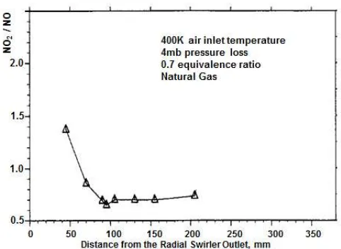
Figure 9: NO2/NO ratio as a function of the distance to the heat exchanger quench zone.
fundamental flammability limits for methane-air, where the
critical flame temperature is 1400K – 1500K [19]. At 400K this is 0.4–0.45Ø and so the observed weak extinction is close to the fundamental flammability limit. This has been shown [19] to be a key requirement for lean low NOx combustion for gas turbine applications and this work shows that it is also a key requirement for domestic water heating low NOx combustion.
The good weak extinction shows that thermal power could be modulated from 0.7Ø to 0.5Ø or the thermal output reduced from 20 kW to 14 kW purely on the fuel flow. Further reduction in power could be made by reducing the air flow, which would also reduce the pressure loss. In associated work, the reduction in the air flow has been shown to occur without a major combustion or NOx problem for pressure losses down to 1mb. This pressure loss change is an air flow reduction of 50%, which would take the minimum thermal output to 7 kW. Thus the design could act as a modulated heat output water heater, with no change in the flame stabilizer geometry.
EMISSIONS AS A FUNCTION OF DISTANCE TO THE HEAT EXCHANGER QUENCH ZONE
The CO emissions are shown in Fig. 6 as a function of the distance to the water cooled heat exchanger. This shows that at the 70mm position, for the optimum thermal efficiency, the CO was 0.02% and the CO/CO2 ratio was 0.002. These are both well inside the UK recommended values [21] of 0.1% CO and 0.02 CO/CO2. Fig. 6 shows that CO and CO/CO2 levels 1/10 of those at the 70mm position could be achieved if a greater distance to the water quench zone was used. This is undesirable due to the reduction in thermal efficiency that occurs when the heat exchanger is moved out of the high turbulence zone.
The THC emissions are shown as a function of the distance to the heat exchanger in Fig. 7. This shows that at the 70mm position the THC was 80ppm. There are no THC emissions regulations for domestic water boilers, apart from those of thermal efficiency. The THC emissions are an energy loss of unreacted fuel and hence influence the thermal efficiency. The combined CO and THC energy loss is shown in Fig. 6 as the combustion inefficiency. At the 70mm burner to heat exchanger separation distance this 0.15%, which is a negligible contributor to the loss in thermal efficiency. As shown in Figs. 6 and 7, much lower CO and THC emissions could be achieved for a greater separation distance.
[image:6.612.51.292.506.682.2]A key reason for these ultra-low NOx emissions is the cooling of the flame as soon as the heat release was complete, so that there was minimal residence time at the 1970K adiabatic flame temperature. The importance of this is shown by the emissions results for the combustor with no heat extraction and a 330mm combustor length. For the present geometry, 4mb pressure loss, 400K inlet temperature and 0.7Ø the NOx emissions were 25ppm at 0% oxygen or 0.6 g/kg. These are still low NOx emissions but now only just meet the 2018 EU [4] and San Joaquin Valley District of California NOx regulations [7] of 0.7 g/kg and 27ppm at 0% oxygen. The increase in NOx was due to the thermal NOx generation over the 260mm distance at close to the adiabatic temperature. The location of the heat exchanger relative to the radial swirler orifice plate exit plane is thus crucial in the achievement of the present ultra-low NOx emissions combined with low CO and UHC emissions.
The major problem with NOx emissions is that they react in the atmosphere to form NO2 which is harmful to humans as it reduces the lung function. Emissions of NO2 directly from combustion systems is thus undesirable. The NO2 emissions as a fraction of the NO emissions are shown in Fig. 9, as a function of the distance from the radial swirler orifice plate outlet plane. At the 70mm optimum location of the water heat exchanger the NO2/NO ratio was 0.87, which is 0.47 NO2/NOx. The direct conversion of NO to NO2 occurs in flame reaction zones through the NO + HO2 = NO2 + OH reaction. The HO2 radical occurs in the flame reaction zone at relatively low flame temperatures of around 1500K [22] and this occurs upstream of the 70mm optimum heat exchanger location. This is why the NO2 conversion increases at the 50mm heat exchanger location in Fig. 9. NO2 decreases as the heat exchanger is moved downstream as the reaction zone remains hotter for longer and HO2 formation of NO2 from NO declines.
CONCLUSIONS
The 2018 EU and San Joaquin Valley District of California NOx regulations for domestic gas fired water heaters, of 56 mg NOx/kWh and 14 g/GJ respectively, convert to 0.7 g/kg and 27 ppm NOx at 0% Oxygen. These NOx emissions were shown to be easily achieved with the proposed radial swirler flame stabiliser design and a water heat exchanger positioned 70mm from the radial swirler outlet plane. These results were for 400K inlet temperature at 0.7Ø, where the adiabatic flame temperature was 1970K and thermal NOx formation was significant. The NOx formation was limited by the heat exchanger cooling the combustion and lowering the flame temperature, just after the heat release was completed. This gave a minimal residence time at the 1970K temperature. The CO and THC emissions were also very low at this low NOx condition.
A 76mm outlet diameter radial swirler with 8mm vane depth was used with fuel injection through the swirler outlet duct wall using 8 3mm equispaced fuel injection holes, one for each radial swirler vane passage. The swirler outlet duct was 60mm long from the back face of the radial swirler. At the outlet of the 76mm duct a 41mm diameter orifice was place that controlled the pressure loss to 4mb. The expansion of the swirler flow from the 41mm outlet diameter to the 140mm
combustor diameter was shown to give high turbulence concentrated close to the 41mm orifice plate outlet. The 60mm long 76mm diameter cavity upstream of the 41mm diameter outlet orifice gave good mixing of the cavity wall injected fuel with the swirling air flow. The geometry gave very stable quiet combustion with a very short flame development length of 70mm.
The positioning of the 6.3mm OD stainless steel water heating coil at the 70mm axial position was shown to give an 89% thermal efficiency and a water thermal heat load of 20 kW. The positioning of the heat exchanger was critical, as it was located in the highly swirling flow in a region of high turbulence. Further downstream the thermal efficiency was much lower, as the gas side swirl velocities and turbulence levels were lower. Overall the design gave a very compact combustion system with ultra-low NOx emissions.
ACKNOWLEDGEMENTS
We would like to thank that Korean Gas Corporation for a partial studentship and the British Council for a research scholarship. The test equipment was provided by several UK EPSRC research grants.
REFERENCES
[1] UK Defra, National Statistics Release: Emissions of air pollutants in the UK, 1970 to 2015, STATISTICAL RELEASE: 21 April 2016.
[2] Abbott, J., Conolly, C. Cooke, S.,Passant, N., Stewart, R., Wagner, A., Assessment of the effectiveness of measures under the Clean Air Act 1993. AEA/R/ED46626/3289, 2012.
[3] US EPA, NOx Control Regulations, 2017.
[4] EU COMMISSION, REGULATION No 813/2013 Implementing Directive 2009/125/EC of the European Parliament and of the Council with regard to ecodesign requirements for space heaters and combination heaters. 2 August 2013
[5] Anonymous, Gas Technology Boiler NOx Emissions, Plant Engineering, 7.20.2010.
[6] Elliot, J., Boiler NOx Emissions and Energy Efficiency. CPAU Facilities Managers Meeting, Bay Area Air Quality Management District, Mar. 10, 2011
[7] San Joaquin Valley Air Pollution Control District. Rule 4905 Natural gas-fired, fan-type central furnaces, 2015.
[8] Alkabie, H.S., Andrews, G.E. and Ahmad, N.T. Lean low NOx primary zones using radial swirlers. ASME Paper 88-GT-245, Proceedings of the ASME 1988 International Gas Turbine Conference, Amsterdam (1988).
[9] Alkabie, H.S. and Andrews, G.E. Ultra-low NOx emissions for gas and liquid fuel using radial swirlers. ASME Paper 89-GT-322. Proceedings of the ASME International Gas Turbine Congress, Toronto (1989).
[10] Alkabie, H.S. and Andrews, G.E. Radial swirlers with peripheral fuel injection for ultra-low NOx emissions. Proceedings of the ASME IGTI International Gas Turbine Congress, Brussels. ASME Paper 90-GT-102 (1990).
[
11] Andrews, G.E., N. Escott, and M.C. Mkpadi, 2008. “Radial swirler designs for ultra low NOx gas turbine combustion”. Proceedings of the ASME Turbo Expo 2008, Hamburg, Germany. ASME Paper GT2008-50406.[13] Boyns, M.B. and Patel, R., 1997. “The Application of DLN
Technology to the Tornado and Tempest Industrial Gas Turbines”.
ASME Turbo Expo 1997, Orlando, USA. ASME Paper 970GT-059.
[14] Andrews, G.E., Alkabie, H.S., Abdul Hussain, U.S. and Abdul Aziz, M., 1993. “Ultra low NOx ultra lean gas turbine primary zones
with liquid fuels”. AGARD 81st Symposium of the Propulsion and Energetics Panel of Fuels and Combustion Technology for Advanced Aircraft Engines. AGARD Conference Proceedings pp.24.1-24.14.
[15] Agbonzikilo, F.E., Owen, I., Sadasivuni, S.K. and Bickerton,
R.A., 2015. “Investigation of Flow Aerodynamics for Optimal Fuel
Placement and Mixing in the Radial Swirler Slot of a Dry Low
Emission Gas Turbine Combustion Chamber”. Proc. ASME Turbo Expo 2015, Montreal, Canada. ASME Paper GT2015-43716.
[16] El-Jummaih, A.M., Abdul Hussain, R.A.A., Andrews, G.E. and Staggs, J.E.J. Impingement Heat Transfer: CHT CFD Predictions of the Influence of Reduced Crossflow using Large Gaps. Proceedings of the 12th International Conference on Heat Transfer, Fluid Mechanics and Thermodynamics, July 2016. Paper HEFAT2016-1570249450. Proceedings p. 1113-1124.
[17] Andrews, G.E. and Ahmad, N.T. (2012) Axial Swirler Outlet Shroud Influences on Premixed Combustion NOx Emissions for all the Combustion Air Passing through the Swirler. Proc. ASME Turbo Expo, Copenhagen. ASME Paper GT2012-68642.
[18] G.E. Andrews, Ultra Low Oxides (NOx) emissions combustion in gas turbine systems. Chapter 16 In: Modern Gas Turbine Systems, Ed. Peter Jansohn, Woodhead Publishing, 2013. pp.715-790.
[19] Andrews, G.E., Ahmed, N.T., Phylaktou, H.N. and King, P., Weak Extinction in Low NOx Gas Turbine Combustors. Proceedings of the ASME International Turbo Expo GT2009, ASME Paper GT2009-59830.
[20] Energy Savings Trust, Domestic Heatingby Gas: Boiler Systems – Gudiance for Installation and Specification. Energy Saving Trust CE30, June 2008.
[21] Cotton, J. and Wilson, M., A Review of Gas Appliance CO Emissions Regulations. Advantica Report R4162, Dec. 2000.