UNIVERSITI TEKNIKAL MALAYSIA MELAKA
IMPROVEMENT ON PUMP FOOTING SYSTEM FOR
MISALIGNMENT CORRECTION.
This report submitted in accordance with requirement of the Universiti Teknikal Malaysia Melaka (UTeM) for the Bachelor Degree of Manufacturing Engineering
(Manufacturing Process) (Hons.)
by
Muhamad Sharul Nizam Bin Zin B051210212
930809-01-5399
UNIVERSITI TEKNIKAL MALAYSIA MELAKA
BORANG PENGESAHAN STATUS LAPORAN PROJEK SARJANA MUDA
TAJUK: Improvement on Pump Footing System for Misalignment Correction
SESI PENGAJIAN: 2015/16 Semester 2
Saya MUHAMAD SHARUL NIZAM BIN ZIN
mengaku membenarkan Laporan PSM ini disimpan di Perpustakaan Universiti Teknikal Malaysia Melaka (UTeM) dengan syarat-syarat kegunaan seperti berikut:
1. Laporan PSM adalah hak milik Universiti Teknikal Malaysia Melaka dan penulis. 2. Perpustakaan Universiti Teknikal Malaysia Melaka dibenarkan membuat salinan untuk
tujuan pengajian sahaja dengan izin penulis.
3. Perpustakaan dibenarkan membuat salinan laporan PSM ini sebagai bahan pertukaran antara institusi pengajian tinggi.
4. **Sila tandakan (SULIT )
TERHAD
TIDAK TERHAD
(Mengandungi maklumat yang berdarjah keselamatan atau kepentingan Malaysia sebagaimana yang termaktub dalam AKTA RAHSIA RASMI 1972)
(Mengandungi maklumat TERHAD yang telah ditentukan oleh organisasi/badan di mana penyelidikan dijalankan)
Alamat Tetap: NO. 98, Jalan Medoi
Padang Lalang, Kampung Jawa
85000, Segamat
Tarikh: 22/06/2016
Disahkan oleh:
Dr Mohd Shahir bin Kasim Cop Rasmi:
Tarikh: _______________________
DECLARATION
I hereby, declared this report entitled “Improvement on Pump Footing System for Misalignment Correction” is the results of my own research except as cited in
references.
Signature : ……….
Author’s Name : Muhamad Sharul Nizam Bin Zin
i
ABSTRACT
ii
ABSTRAK
iii
DEDICATION
To my beloved parent, Zin bin Asiban, Aishah Bt Aziz,
My Supervisor, Dr Mohd Shahir bin Kassim
My friends and technician that involve in this study, May Allah ease our journey and bless all of us.
iv
ACKNOWLEDMENT
Primarily, all praises to The Almighty as for His mercy and grace, I was able to
complete Final Year Project just in time. I would like to seize this opportunity to thank all
parties who have contributed along the process of the completion of Final Year Project.
I would like to express my sincere appreciation to my final year project
Supervisor Dr Mohd Shahir bin Kasim for his constant supervision, guidance and encouragement, without which this project would not have been possible. I am truly grateful for his unwavering support through the whole period of this final year project. Taught all the manufacturing knowledge and share experience to me and also taught me how to handle work in proper manner.
I would like to express my gratitude to all the lectures and staff for their immense interest in my topic of project, for providing me material and helping me to solve problem that I could not possibly have discovered on my own. Also which really spends their time to teach me a lots of knowledge regarding to the design development.
To my family, who raised and taught me that all the knowledge of life that we cannot get from school. To get the best knowledge that can teach us is by learning through our own mistake. All the mistakes that has been done by us can make us stronger and turn us to wise person. It not easy to learn something that new for us, learning can be hard sometimes but with hard and strong perseverance, nothing can stop us learn and gain experience.
v
TABLE OF CONTENT
Abstract i
Abstrak ii
Dedication iii
Acknowledgement iv
Table of Content v
List of Tables ix
List of Figures x
List Abbreviations, Symbols and Nomenclatures xiii
CHAPTER 1: INTRODUCTION 1
1.1 Background 1
1.2 Problem Statement 2
1.3 Research Objectives 3
1.4 Scope 4
1.5 Chapter Overview 4
CHAPTER 2: LITERATURE REVIEW 5
2.1 Shaft Alignment 5
2.2 Misalignment 6
2.2.1 Type of Misalignment 7
2.2.1.1 Angular Misalignment 8
2.2.1.2 Offset Misalignment 8
2.3 Effect of misalignment 9
2.3.1 Machine Efficiency 9
2.3.2 Vibration 10
2.3.3 Thermal Growth 12
2.4 Method of Alignment 13
2.4.1 Straightedge/Feeler Gauge 13
vi
2.4.3 Laser Alignment Method 16
2.5 Shaft Alignment Tolerances 17
2.6 Soft Foot 18
2.6.1 Type of Soft Foot 18
2.6.1.1 Parallel 18
2.6.1.2 Bend Soft Foot 19
2.6.1.3 Squishy 20
2.6.2 Caused of Soft Foot 20
2.6.3 Effect of Soft Foot 21
2.6.4 Soft Foot Correction 22
2.6.4.1 Shim for Correction 24
2.7 Current Available Product 27
2.7.1 Shimless Footing System 27
2.7.2 Levelling Jack 28
2.8 Bearing. 29
2.9 Finite Element Analysis (FEA) 30
CHAPTER 3: METHODOLOGY 31
3.1 Research Methodology 31
3.2 Project Flowchart 32
3.3 Gantt Chart 35
3.4 Selection Required Criteria and Specification. 36 3.4.1 Determination of the Criteria for Concept Selection list 37
3.5 Concepts Generation 37
3.5.1 Concept Selection Using the Pugh Selection Method 37
3.5.2 Concept Screening 38
3.5.2.1 Prepare the selection matrix 38
3.5.2.2 Rate The Concept 39
3.5.2.3 Rank The Concept 40
3.5.2.4 Combine and Improve the Concepts 40
3.5.2.5 Select One or More Concept 41
3.5.2.6 Reflect On the Result and The Process 41
vii
3.5.3.1 Prepared The Selection Matrix 42
3.5.3.2 Rate The Concept. 42
3.5.3.3 Rank The Concept 43
3.5.3.4 Combine and Improve the Concept 43
3.5.3.5 Select One Or More Concept 43
3.6 Fabrication of The Product 44
3.6.1 Technical Drawing 44
3.6.2 Fabrication Planning and Process 44
3.6.3 Material 46
3.7 Product Analysis 46
3.7.1 Simulation of the prototype 47
3.7.2 Validation of the scale of the product 47
CHAPTER 4: RESULTS & DISCUSSIONS 49
4.1 Determine list of criterions for concept generation and selection 49
4.2 Conceptual design generation 51
4.3 Product Mission Statement 52
4.4 Concepts Selection Method 53
4.4.1 Concept Screening Phase 53
4.4.2 Concept Scoring Phase 56
4.4.3 Discussion of Concept Selection Method 57
4.5 Prototype Building of Pump footing system 57
4.5.1 Technical Drawings Prototype of Pump Footing System 57
4.5.1.1 Analysis on technical drawing 58
4.5.2 Cost of Manufacturing Pump Footing System 61
4.5.3 Bill of material 62
4.5.4 Fabrication planning and procedure 63
4.6 Degree of freedom of the pump footing system 64
4.7 Analysis on Pump footing system 68
4.7.1 Linear stress simulation analysis 68
4.7.2 Safety factor of the product 72
4.8 Validation of scale 75
viii
CHAPTER 5: CONCLUSIONS & FUTURE WORKS 81
5.1 Conclusions 81
5.2 Future Works and Recommendations 82
5.3 Sustainability Development 83
REFERENCES 84
ix
LIST OF TABLES
2.1 Shaft alignment tolerances 17
2.2 Size of Shim 25
3.1 Gantt Chart for PSM Semester 1. 35
3.2 Gantt Chart for PSM Semester 2. 36
3.3 Screening Matrix Table 39
3.4 Codes Used in Concept Screening Stage 40
3.5 Concept Scoring Matrix Template 42
3.6 Scale That Has Been Used for Concept Rating 43
3.7 General information of Stereo Microscopes Machine Specification 48
4.1 Criteria for concept generation and selection 50
4.2 Conceptual design generation and description 51
4.3 Mission statement 52
4.4 Concept screening phase 54
4.5 Concept scoring phase for pump footing system 56
4.6 Budget to fabricate a pump footing system 61
x
LIST OF FIGURES
2.1 Correct shaft alignment 5
2.2 Shaft alignment on the vessel 6
2.3 Example of misalignment 7
2.4 Angular misalignment 8
2.5 Offset misalignment 9
2.6 Graph before alignment 11
2.7 Graph after alignment 12
2.8 Example of straightedge process 14
2.9 Face and rim method using dial indicator 14
2.10 Rim readings on the outside surface of a shaft 15
2.11 Laser alignment method 16
2.12 Parallel soft foot 19
2.13 Bend soft foot 19
2.14 Squishy soft foot 20
2.15 An example of preload on the bearings 21
2.16 Measure soft foot with feeler gauge and fill gap completely 22
2.17 Checking for soft foot 23
2.18 Step shimming 23
xi
2.20 Various size of shim 26
2.21 Shimless footing system 27
2.22 Levelling jack 28
2. 23 Pillow Block bearing 29
2.24 FEA analysis on gear shaft 30
3.1 Project flowchart 33
3.2 Steps in the design process 34
3.3 5- axis CNC machine for fabrication process. 45
3.4 Tapping process for threading the product. 45
3.5 Meiji Stereo Microscopes type EMZ 48
4.1. Dimension of the wedge at the original position 58
4.2. Dimension of the wedge at the maximum position 59
4.3. Explode drawing of final product design 60
4.4. Orthographic drawing of final product design 60
4.5. Isometric drawing of final product design 61
4.6. Bill of material of the product component 62
4.7. Process flow chart in the fabrication of pump footing system 63
4.8. The degree of freedom of the product 64
4.9. The detail of the product component 65
4.10. Detail of front view of the product 66
4.11. Illustration of the motor pump sitting independently on the footing system 67
xii
4.13. Meshing process of the product part 69
4.14. Linear stress analysis simulation result at maximum elevated position 70
4.15. Linear stress analysis simulation result at the original position 71
4.16. Result of factor of safety of the simulation at maximum travel position 72
4.17. Result of factor of safety of the simulation at the original position 73
4.18. Result of factor of safety of the simulation when 4600 N subjected on it 74
4.19. Clear image of graduation lines and its thickness in 25x magnification 76
4.20. Length of minimum tolerance under 25x magnification 76
4.21. Length of maximum tolerance under 25x magnification 77
4.22. Footing system installed on shaft alignment rig 78
4.23. Vibration meter and sound analyzer reading before alignment 79
xiii
LIST OF ABBREVIATIONS, SYMBOLS AND
NOMENCLATURES
2D - 2 Dimension
3D - 3 Dimension
CAD - Computer Aided Design
CNC - Computer Numerical Control
dB - Decibel
FEA - Finite Element Analysis
HP - Horse Power
Kg - Kilogram
mm - Millimetre
N - Newton
NC - Numerical Control
PSD - Positioning Sensing Detector
PSM - Projek Sarjana Muda
RM - Ringgit Malaysia
rpm - Rotation per minute
1 This section describes the background, objectives, problem statement and scope of the project. Finally, this section ends with an overview about the end of the reporting year. The background is discussing about the misalignment of the shaft and the fundamental knowledge about it. Lastly, the objective explained on the goals to be achieved for this subject and scope encompasses everything what should have been done in this project.
1.1 Background
Over the past few years, billions of dollars were loss by industry worldwide due to misalignment of machinery problem. Rotating shaft and motor are widely uses in industry to produce steel, glass, petroleum, electrical, the food we eat, and also our transportation. Besides, everything around us are being influenced by rotating dynamic machinery. It has been revealed that shaft alignment appears to have taken a more crucial role during installing and servicing machinery. Proper alignment of the shaft ensures smooth, efficient delivery of power to the motor-driven equipment (Piotrowski, 2006).
2 Studies have been revealed that misalignment or also known as soft foots slowly damage the machinery over a certain period of time. Misalignment also leads to premature machinery failures such as noise, vibration, shaft failure, bearing temperature increase, coupling wear and shaft failure. This critical problem caused a huge amount of financial loss due purchasing the new machine part and loss of production (Ahmed et. al., 2010) .
The aim of this studies is to examine the effect of soft foots on the shaft alignment and to do improvement of shimless footing system in rotating machinery industry. Small improvement in motor pump can cause high impact result on the performance of rotating machinery (Jesse et al., 1970). The study begins with chapter one which include the overview of the study, problem statement, and the objective of the study. Then, proceed with the scope of the study, research methodology and the organization of the report.
1.2 Problem Statement
Angular misalignment, in particular in motor and pump can cause severe damage to the driven equipment and the motor. They would cross one another, as opposed to superimpose or keep running along a typical centerline (Tsiafis et al., 2015).
The alignment specialist needs more broad learning and skill than basically swinging reading the dial indicator and shimming machine feet, however adjusting shaft to be coaxial is a decent place to begin (Wowk, 2001).
3 The current manual alignment by using shim are difficult due to pre-cut shim only come with standard sizes and the tolerances are different according to it manufacture. Moreover, no permanent correction can be achieved because shim correction doesn’t match up with the actual alignment correction reading due to limited shim thickness. Only three shim can only be stepped per feet since to many shims under a machine foot prompts expanded risk of soft foot (Luedeking, 2013).
Casanova (2008), state that if machining alignment can be improved, the rate of failure decline significantly. Failure of equipment is a lead to major maintenance expense and have numerous incidental or associated costs. Truth be told, the expense of parts and work to repair the machine can be one of the expenses. Lost production, consequential damages, contractual penalties, and liability for injury can lead to more expensive than the repair itself.
The shaft support and machine frame structure both together influenced the shaft vibration response and its location in the frequency range, additionally the machine support. Assembly frame, and its foundation influence the shaft vibration response and the consequence of the natural frequencies of the foundation in the machine operational range may bother the operation and ought to be covered in the machine design (Leso et al., 2011).
1.3 Research Objectives
i. To design and develop improved footing system that eliminate soft foot. ii. To produce a device that can do fine tuning during the shaft alignment
process.
4
1.4 Scope
This paper focus on the main scope of study, which is to study and analyses the effect of soft foot during the alignment process. It also reviews the fundamental of shaft alignment process that will be improved the understanding of the shaft alignment and its problem. Moreover, this paper describes the important steps in the design and development the improved footing system which must realize and identify the problems that might occur during the construction of the footing system. Finally, to analyse the effectiveness of current unit compared with conventional shim to correct problems of misalignment.
1.5 Chapter Overview
PSM I cover five chapters consist of introduction, literature review and methodology. Chapter 1 is all about introduction of the project, problem statement related to current issues, object, scope of the study and the significant of the study.
Chapter 2 is the literature review section. Literature review are normally based on the gathered of references from various information sources such as journals, books, website etc., it will discuss about the current finding, method use and result of the related topic that found in the journal paper, books or articles.
5 The main focus of this study is to do an improvement on the footing system for misalignment correction. This chapter review and explained about the past studies that is done. Literature review is virtually examining respectively to the source and described to justify the statement with proof of research or study in related field.
2.1 Shaft Alignment
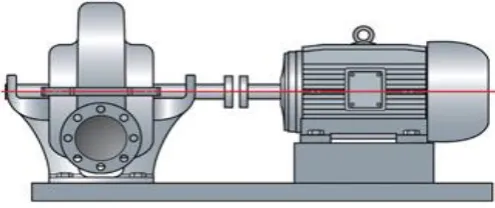
[image:21.595.176.424.595.699.2]Shaft Alignment is a process where two or more machines such as motors and pumps are located such that at the point of transfer of power from one shaft to another, the axis of rotation of the two shafts to be aligned when the engine is running under normal conditions (Prüftechnik, 2010). Acceptable shaft alignment marked bearing arrays, with a particular position in the vertical direction, providing a satisfactory distribution of load bearing, under all working conditions (Low & Lim, 2004). Figure 2.1 shows the correct shaft alignment under normal working condition.
Figure 2.1 : Correct Shaft Alignment (Service, 2015).
LITERATURE REVIEW
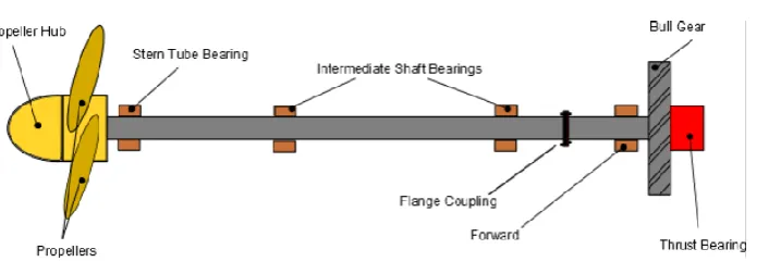
6 Perfect alignment is crucial to the working life of the rotating part. Bearings, mechanical seals, packing, and couplings are straightforwardly influenced by the alignment of shaft center lines. The objective of the alignment procedure is to make a straight line through the coupling. The two coupled shafts are thought to be splendidly adjusted when their middle lines are coaxial in the working condition (Services, 2015). D.Keane (2014), in his journal stated that the correct shaft alignment is very important for these vessels as exceptional bending moments or shear forces are directly transferred to the rear of the engine bearings as shown in Figure 2.2. Depending on the deflection of the body and engine bearings sagging bed-plates can be unloaded and moved them to the front bearing load at the front.
Figure 2.2 : Shaft alignment on the vessel (Keane, 2014).
2.2 Misalignment
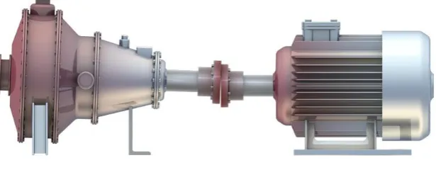
7 Figure: 2.3 : Example of Misalignment (ThermAlign, 2014).
It is not generally simple to identify misalignment on machining that is running. The radial force that is transmitted from shaft to shaft are hard to quantify remotely. Figure 2.3 shows that misalignment error at the coupling transmission planes, where conceivable this system process to be discouraged for other dial or laser routines for arrangement (Prüftechnik, 2010).
2.2.1 Type of Misalignment
8 Angular Misalignment
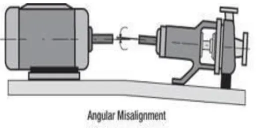
[image:24.595.186.453.281.409.2]Angular misalignment occurs when the motor is set at an angle to the driven components. Angle or mislaid can occur to one side or the right, or below the beneath. On the off chance that the centerline of the engine and the driven shaft is extended, they would cross one another, instead of superimpose or keep running along a typical centerline. As shown in Figure 2.4, angular misalignment can bring about serious harm to the driven component and the motor (Advanced Manufacturing, 2012).
Figure 2.4 : Angular Misalignment (Metal, 2015).
Offset Misalignment