Dissertation Submitted to
THE TAMIL NADU DR. M.G.R. MEDICAL UNIVERSITY in Partial fulfilment for the degree of
MASTER OF DENTAL SURGERY
BRANCH - V
This is to certify that the dissertation entitled “Accuracy of Bracket Positioning in Direct and Indirect Bonding Technique” by Dr. C.Jegan kumar Post graduate student (M.D.S), Orthodontics (branch V), Tamil Nadu Govt. Dental College and Hospital, Chennai, submitted
to the Tamil Nadu Dr. M.G.R. Medical University in partial fulfilment
for the M.D.S. degree examination (April 2013) is a bonafide research
work carried out by him under my supervision and guidance.
Guided by
DR. G. VIMALA M.D.S., Professor,
Dept. of Orthodontics and dentofacial orthopedics, Tamil Nadu Govt Dental College & Hospital,
Chennai - 600 003.
Dr. M.C.SAINATH M.D.S., Dr. K. S. G. A. NASSER M.D.S.,
Professor and Head of the Department, Principal ,
Dept. of Orthodontics&dentofacial orthopedics TamilNadu Govt. Dental College&Hospital, TamilNadu Govt. Dental College & Hospital, Chennai- 600 003.
I, Dr. C.JEGAN KUMAR , do hereby declare that the dissertation titled “ACCURACY OF BRACKET POSITIONING IN
DIRECT AND INDIRECT BONDING TECHNIQUE” was done in the
Department of Orthodontics, Tamil Nadu Government Dental College
& Hospital, Chennai 600 003. I have utilized the facilities provided in
the Government Dental College for the study in partial fulfilment of the
requirements for the degree of Master of Dental Surgery in the
speciality of Orthodontics and Dentofacial Orthopaedics (Branch V)
during the course period 2010-2013 under the conceptualization and
guidance of my dissertation guide, Professor Dr. G. VIMALA M.D.S.
I declare that no part of the dissertation will be utilized for
gaining financial assistance for research or other promotions without
obtaining prior permission from the Tamil Nadu Government Dental
College & Hospital.
I also declare that no part of this work will be published either in
the print or electronic media except with those who have been actively
involved in this dissertation work and I firmly affirm that the right to
preserve or publish this work rests solely with the prior permission of
the Principal, Tamil Nadu Government Dental College & Hospital,
Chennai 600 003, but with the vested right that I shall be cited as the
author(s).
Signature of the PG student Signature of the HOD
My sincere thanks to Dr. K.S.G.A. NASSER, M.D.S., Principal,
Tamil Nadu Government Dental College and Hospital, Chennai-3, for
his kind support and encouragement.
I owe my thanks and great honour to Dr. M.C. SAINATH M.D.S,
Professor, Head of the Department, Department of Orthodontics and
Dentofacial Orthopaedics, Tamilnadu Govt. Dental College and
Hospital, Chennai3, for helping me with his valuable and timely
suggestions and encouragement.
I express my deep sense of gratitude and great honour to my
respected guide, Professor Dr. G. VIMALA M.D.S., Department of
Orthodontics and Dentofacial orthopaedics, Tamilnadu Govt. Dental
College and Hospital, Chennai-3, for her patience guidance, support
and encouragement throughout the study.
I owe my thanks and great honour to Dr. S. PREMKUMAR M.D.S,
Professor, Department of Orthodontics and Dentofacial Orthopaedics,
Tamilnadu Govt. Dental College and Hospital, Chennai3, for helping
me with his valuable and timely suggestions and encouragement.
I am grateful to Dr. B. BALASHANMUGAM, M.D.S.,
I am grateful to Dr. USHA RAO, M.D.S., Assistant Professor,
Department of Orthodontics, Tamilnadu Government Dental College
and Hospital, Chennai-3 for her support and encouragement.
I am grateful to Dr. K. USHA, M.D.S., Assistant Professors,
Department of Orthodontics, Tamil Nadu Government Dental College
and Hospital, Chennai –3 for her support and encouragement.
I thank Mr. K. BOOPATHI M.Sc., M.Phil, for helping me with
the Statistics in the study.
I take this opportunity to express my gratitude to my friends and
colleagues for their valuable help and suggestions throughout this
study.
I offer my heartiest gratitude to my family members for their
selfless blessings.
I seek the blessings of the Almighty God without whose
This agreement herein after the “Agreement” is entered into on this
day...day of December 2012 between the Tamil Nadu
Government Dental College and Hospital represented by its Principal having address at Tamilnadu Government Dental college and Hospital,
Chennai-03, (hereafter referred to as , ’the college’)
And
Dr. G. VIMALA aged 44 years working as professor at the college, Having Residence address at AP 115, 5th Street, AF Block, 11th Main
Road, Anna Nagar, Chennai, Pin: 600 040, India (herein after referred
to as the ‘Principal Investigator’)
And
Dr. C. JEGAN KUMAR aged 27 years currently studying as postgraduate student in department of Orthodontics in Tamilnadu
Government Dental College and Hospital (herein after referred to as the
‘PG/Research student and co- investigator’).
Whereas the ‘PG/Research student as part of his curriculum undertakes
to research on “Accuracy of Bracket positioning in Direct and Indirect bonding technique” for which purpose the PG/Principal investigator shall act as principal investigator and the college shall
Whereas the parties, by this agreement have mutually agreed to the
various issues including in particular the copyright and confidentiality
issues that arise in this regard.
Now this agreement witnesseth as follows:
1. The parties agree that all the Research material and ownership
therein shall become the vested right of the college, including in
particular all the copyright in the literature including the study, research
and all other related papers.
2. To the extent that the college has legal right to do go, shall grant to
licence or assign the copyright do vested with it for medical and/or
commercial usage of interested persons/entities subject to a reasonable
terms/conditions including royalty as deemed by the college.
3. The royalty so received by the college shall be equally by all the
parties.
4. The PG/Research student and PG/Principal Investigator shall under
no circumstances deal with the copyright, Confidential information and
know – how generated during the course of research/study in any
manner whatsoever, while shall sole vest with the manner whatsoever
student.(co-investigator)
6. The college shall provide all infrastructure and access facilities
within and in other institutes to the extent possible. This includes
patient interactions, introductory letters, recommendation letters and
such other acts required in this regard.
7. The principal investigator shall suitably guide the student Research
right from selection of the Research Topic and Area till its completion.
However the selection and conduct of research, topic and area research
by the student researcher under guidance from the principal investigator
shall be subject to the prior approval, recommendations and comments
of the Ethical Committee of the college constituted for this purpose.
8. It is agreed that as regards other aspects not covered under this
agreement, but which pertain to the research undertaken by the student
Researcher, under guidance from the Principal Investigator, the
decision of the college shall be binding and final.
9. If any dispute arises as to the matters related or connected to this
agreement herein, it shall be referred to arbitration in accordance with
agreement in the presence of the following two witnesses.
College represented by its Principal PG Student
Witnessess Student Guide
1.
S.NO. TITLE PAGE NO.
1. INTRODUCTION 01
2. AIMS AND OBJECTIVES 04
3. REVIEW OF LITERATURE 05
4. MATERIALS AND METHODS 18
5. RESULTS 33
6. DISCUSSION 53
7. SUMMARY AND CONCLUSION 60
S.No. Title Page no
1. Independent samples T-Test to compare the mean deviations 36
between Direct and Indirect methods
2. Independent samples T-Test to compare the mean deviations 37
with direction between Direct and Indirect methods
3. Independent samples T-Test to compare the mean deviations 38
between Direct and Indirect methods in each quadrant
First quadrant
4. Independent samples T-Test to compare the mean deviations 38
between Direct and Indirect methods in each quadrant
Second quadrant
5. Independent samples T-Test to compare the mean deviations 39
between Direct and Indirect methods in each quadrant
Third quadrant
6. Independent samples T-Test to compare the mean deviations 39
between Direct and Indirect methods in each quadrant
Fourth quadrant
7. Independent samples T-Test to compare the mean deviations 40
with directions between Direct and Indirect methods in each
quadrant - Second quadrant
9. Independent samples T-Test to compare the mean deviations 42
with directions between Direct and Indirect methods in each
quadrant - Third quadrant
10.Independent samples T-Test to compare the mean deviations 43
with directions between Direct and Indirect methods in each
quadrant - Fourth quadrant
11.Proportions of values showing the direction of deviations 44
12.The mean magnitude of deviations between Direct and 45
Indirect methods – Toothwise
13.The mean direction of deviations between Direct and 46
Indirect methods in +ve direction
14.The mean direction of deviations between Direct and 47
Background
Pre adjusted edgewise appliances have inbuilt tip, torque and anti-rotation elements. As they incorporated in the bracket itself, final tooth positioning is mostly influenced by the initial bracket positioning. Hence, bracket positioning must be precise and minor deviation can affect the final tooth positioning adversely.
Objective
To compare the direct and indirect bracket bonding techniques to identify the bonding technique which enables the most accurate bracket positioning.
Materials and Method
30 patients were selected and were divided into Group A and Group B. In Group A direct bonding in 1st and 3rd quadrants and indirect bonding in 2nd and 4th quadrants were planned. Group B receives bonding in opposite way. Brackets were placed according to Roth prescription. Dual Transfer tray was prepared with light body and putty C-silicone. Sondhi rapid set resin was used for indirect bonding. Photographs of all anterior teeth with brackets were taken after complete bond up in standardized manner. These photographs were analysed with GIMP 2.8.2 software for errors in bracket height, mesiodistal position and angulation with magnitude and direction.
Results
Errors in vertical and mesiodistal positioning were statistically significant between direct and indirect bonding technique. Though angulation errors exist in both techniques, they were not statistically significant between these techniques.
Conclusion
1
INTRODUCTION
Orthodontic treatment aims at achieving functional occlusion, facial aesthetics
and stability of the treatment results. These goals are achieved by orthodontic
or orthopaedic corrections depending on the nature of dentoalveolar and
skeletal derangements. In most cases, it is the orthodontic repositioning of
teeth, achieved through fixed orthodontic appliances. Fixed orthodontic
appliances have better delivery and control of prescribed force and therefore
offer excellent opportunity for controlled tooth movement.
Edgewise appliance, introduced by Angle in the year 1928 is the prototype of
present day’s fixed orthodontic appliances. Edgewise brackets were welded on
bands and cemented over teeth. As the edgewise brackets had neutral slots, tip
torque and rotation of each tooth was achieved by complex wire bending.
Lawrence Andrews introduced the concept of incorporating tip and torque into
each bracket, after a thorough understanding of requisites of an ideal
occlusion. These brackets were designed in such a way that, when all teeth are
aligned in an ideal arch position, a rectangular arch wire would passively fill
the full slot of all the brackets. Hence precise positioning of each bracket in a
prescribed place became the utmost important determinant in achieving
2
With introduction of composites46, directly attaching a bracket in a specific
position on tooth surface became possible. This ‘direct bonding technique’
eliminated a medium of a band between bracket base and tooth surface and
could directly transmit the intended force.
Due course in 1972, ‘indirect bonding technique’19
was suggested by
Silverman & Cohen. With introduction of newer composites with improved
properties, indirect bonding technique is now becoming popular.
Direct bonding technique has the advantage of being simple and economical.
This technique requires no special armamentarium or lab support. The
disadvantage of this technique is that it requires more chair side time and
limited visibility makes access and positioning of brackets especially on
posterior teeth difficult. Indirect bonding technique overcomes the
disadvantages of direct bonding technique. It consumes less of chair side time
and precise positioning of brackets is possible. Requirement of lab work and
additional expense incurred are the disadvantages of indirect bonding
technique.
As both direct and indirect bonding techniques have equal advantage and
disadvantages, there exists a need to identify the most suitable bonding
technique. Studies reported so far to identify the most preferred bonding
3
Hence this study was aimed at identifying the best bonding technique by
comparing the accuracy of bracket positioning done by direct and indirect
4
Aim
The aim of this study was to compare the direct and indirect bracket bonding
techniques to identify the bonding technique which enables the most accurate
bracket positioning.
Objectives
To measure the variation in vertical positioning of brackets in direct and indirect bonding techniques.
To measure the variation in horizontal positioning of brackets in direct and indirect bonding techniques.
5
REVIEW OF LITERATURE
Indirect bonding was first described in detail as a concept in 1972 by
Silverman and Cohen19. Some of the initial trials used softened Sugar Daddy®
candy (Tootsie Roll, Inc., Chicago, IL) as a means of attaching the brackets to
the working models before transfer tray fabrication. Others have used
water-soluble adhesives and even sticky wax to attach the brackets to the models.
Eventually this concept evolved to include application of various
adhesive-coated brackets as a means of creating custom bases to aid in the bonding
process.
Michel Buonocore36 (1955) introduced acid etching technique for increasing the adhesion of acrylic filling material to the tooth. He used 85% phosphoric
acid to etch the tooth surface based on the thought that a simple
decalcification that removes the superficial enamel layer is all that is needed
to increase the adhesion of acrylic to tooth structure.
Rafael Bowen46 (1962) discovered a new, stronger resin material for restorative work. The dental filling material consisted of vinyl silane treated
fused silica and a binder consisting of the reaction of product of Bis phenol
6
George Newman22 (1965) used basics of acid etching technique to attach orthodontic appliances to the teeth for orthodontic treatment. He used
polyamide cured epoxy resin and 40% phosphoric acid for enamel
conditioning to bond the plastic attachments to tooth surface.
Thomas E. Perkowski60 (1970) described the clinical and laboratory procedures for indirect method of appliance construction. These appliances
include the bands with all attachments precisely placed, arch wires including
lingual arches and all retraction assemblies, root springs, extra oral appliances,
sutural expansion devices, extra bands for soldered retainers and tooth
positioners.
Silverman E and Cohen M19 (1972) first explained about indirect bonding of brackets. They described the universal direct bonding system for both metal
and plastic brackets in which they described in detail about the indirect
bonding technique.
Michael D. Simmons37 (1978) described the use of caramel candy to position the brackets on the model and stated that caramel candy can be washed with
hot water from the bracket bases and allows bracket removal from model with
7
Bjorn U. Zachrisson and Bjiirn Brobakken14 (1978) conducted a study to compare direct and indirect bonding and stated that direct bonding shows the
advantages of (1) better bracket fit to the tooth surface (2) easier to remove
excess around the bracket bases (3) the entire contact area of bracket base was
constantly filled with adhesive.
Farhad Moshiri, Michael D. Hayward21 (1979) described about the water soluble, heat resistant resin adhesive to position the brackets on the model. He
stated that it allowed the bracket to be embedded in the transfer tray and heat
resistant was advantageous during transfer tray fabrication in vacuum
pressure.
Royce G Thomas49 (1979) discussed a modification of the Silverman and Cohen technique in which Concise® (3M Unitek, Monrovia, CA) or
Dyna-bond® (3M Unitek) was used to form a custom base. This technique was the
first to describe the construction of these custom composite bases, and utilized
a two-part liquid sealant to bond the brackets to the dentition with the aid of a
clear vacuum-formed transfer tray.
Myrberg, Warner40 (1982) presented a technique in which individual bracket placement indicators were made for each tooth based on the concept of a
dental setup that suits the individual functional, occlusal, and esthetic
8
Barry D. Hoffman11 (1988) developed an indirect bonding technique that combines the diagnostic setup of tooth positioners with the customized
bracket placement and level arch of straight-wire appliances.
Richard A. Hocevar, Howard F. Vincent47 (1988) found that 44% of the direct bonds fractured predominantly at the bracket-adhesive interface,
whereas 72% of the indirect bonds failed mainly at the enamel-resin interface.
Thus the indirect bonding promised similar bond strength and easier
debonding because less resin was left on the teeth.
Jim W. milne, George F.Anderson25 (1989) stated that tensile bond strength determinations showed no statistically significant differences between direct
and indirect bracket application methods for incisors and premolars. The
selection of one bonding method over another may therefore be determined by
the accuracy of bracket positioning and the convenience in handling the
materials. The indirect method of bonding may result in more consistently
accurate bracket placement, especially for the inexperienced operator.
Stephen J. Reichheld, Robert A. Ritucci, Anthony A. Gianelly54 (1990) used individual preformed height gauges to position the brackets on the
9
Ronald B. Cooper, Marguerite Goss, Warren Hamula51 (1992) discussed the advantages of using light-cured adhesives for indirect bonding. He listed
several advantages including unlimited working time during bracket
placement, less bracket drift on the working models, and less patient
discomfort because of the acceleration of bracket bonding.
Ronald B. Cooper, Nile A. Sorenson50 (1993) described the use of adhesive pre coated brackets in indirect bonding and listed consistency and accuracy of
bracket positioning, ease of clean up, and elimination of waste as benefits.
Wolfgang carstenson63 (1993) conducted a study between 37% and 2% phosphoric acid to find out the bracket failure rate and stated that there was no
significant difference in bracket failure between the two groups and 2% of
phosphoric acid can be sufficient for the bracket bonding and they showed
less adhesive on teeth surface after debonding.
Jing-yi shiau et al26 (1993) conducted a study to evaluate the bond strength of aged precoated bracket base composite and stated that most failures occur at
bracket composite interface rather than enamel composite interface.
Michael J.F. Read, Andrew I. Pearson38 (1998) discussed the use of a light-cured, lightly filled sealant to attach brackets with a custom resin base to the
10
Bon Chan Koo, Chun-Hsi Chung and Robert L. Vanarsdall13 (1999) conducted a study to evaluate the accuracy of bracket placement in direct and
indirect technique and stated that both direct and indirect bonding techniques
failed to execute ideal bracket placement. On individual teeth, there was no
statistically significant difference in the accuracy of bracket placement
between these two bonding techniques.
Larry W. White31 (1999) used a self-etching primer and a quick cure composite adhesive in indirect bonding. A power slot light-curing tip was
used on each of the teeth in the tray for 3 seconds per tooth. This power slot
tip is broader at the end and concentrates the light for more rapid curing of the
adhesive.
John T. Kalange27 (1999) presented a technique using vertical and horizontal reference lines on working models for bracket placement based on level
marginal ridges, functional occlusal contacts, and esthetic surfaces.
Anoop sondhi4 (1999) introduced a new resin designed specifically for indirect bonding. He presented a cohesive and complete system for fabricating
11
Domenico Dalessandri, Michela Dalessandri, Stefano Bonetti, Luca Visconti, Corrado Paganelli16 (2000) concluded that during the first 4 months after brackets placement, indirect bonding protocol allowed for
significant reduction in plaque accumulation around the braces and reduced
onset of white spots during the orthodontic treatment.
Birte Melsen, Piero Biaggini12 (2002) described about Ray Set® (Biaggini Medical Devices, La Spezia, Italy), exemplified the concept of accuracy of
bracket placement in indirect bonding by using a sophisticated device to bond
preadjusted brackets that reflect individually prescribed requirements for tip,
torque, and rotation independent of bracket height or shape of teeth.
Arndt Klocke, Jianmin shi, Ba¨rbel Kahl-Nieke, Ulrich Bismayer7 (2003) stated that contamination after primer application resulted in an increased risk
of bond failure at clinically relevant levels of stress.
T. M. Hodge, A. A. Dhopatkar, W. P. Rock and D. J. Spary55 (2004) stated that there was no difference between mean bracket placement errors for direct
or indirect methods. The range of error in the three directions assessed was
greater for direct than indirect placement.
12
Arndt Klocke, Jianmin Shi, Ba¨rbel Kahl-Nieke, Ulrich Bismayer8 (2003) used brackets bonded to bovine teeth with multiple indirect techniques
involving chemically, thermally, and light-cured composites and direct
bonded light cured composites, and found comparable bond strengths for all
groups.
Tancan Uysal, Zafer Sari, Abdullah Demir57 (2004) found statistically significant differences among the groups of flowable composites and
conventional orthodontic adhesive. The Shear Bond Strength values were
significantly lower in flowable composite groups than the orthodontic
adhesive. The use of flowable composites is not advocated for orthodontic
bracket bonding because of significantly lower Shear bond strength values
achieved.
Arndt Klocke, Drazen Tadic, Farhad Vaziric and Ba¨rbel Kahl-Nieke5 (2004) stated that pre aging of the custom base composite upto 30 days did not affect shear bond strength and mean bond strength values exceeded 15 MPa.
Bond strength measurements for groups with a custom composite base aged
for a longer interval (100 days) before sealant polymerization were
significantly lower. On the basis of the results of this study, clinicians can
safely use custom base composites aged up to 30 days when using the Thomas
13
William J. Redmond et al62 (2004) described the use of OrthoCAD® (Cadent, Inc., Carlstadt, NJ), plaster models are sent to a processing
department within the company, and stereolithography is used to create a
digital model and bracket positioning will be established using a pen-sized
wand consisting of a tip, a miniature video camera, and LEDs that allow for a
virtual setup.
Arndt Klocke, Jianmin Shi, Ba¨rbel Kahl-Nieke, Ulrich Bismayer6 (2004) stated that, for groups bonded with Maximum Cure or Sondhi Rapid Set sealants, no influence of debonding time on shear bond strength was found.
The Custom I.Q. sealant groups showed significantly lower bond strength
measurements when debonded at the recommended tray removal time, and
higher risk of bond failure at clinically relevant levels of stress. All base
composite-sealant combinations showed acceptable bond strength at 30
minutes and 24 hours after bonding of the sealant.
Omu¨ r Pola, Tancan Uysal, Ali Ihya Karaman42 (2004) stated that indirect bonding of brackets with Sondhi Rapid Set after the application of the
antimicrobial varnish showed significantly lower Shear Bond Strength when
compared with both the indirect bonding - antimicrobial group, and direct
14
Eliades and coworkers18 (2005) validated the importance of reference to marginal ridges versus the centre of the clinical crown as a reference point,
when they demonstrated that positioning brackets using the centre of the
clinical crown resulted in marginal ridge discrepancy between the premolars
and molars and a lack of occlusal contacts with the opposing dentition.
Rohit Sachdeva et al48 (2005) described the use of SureSmile® (Orametrix, Inc., Richardson TX) ,which is based on a white light intraoral scanner that
captures real-time, in vivo images of the dentition. These images can be
manipulated in the form of a three-dimensional digital diagnostic setup and
can be used to determine the bracket position on teeth.
Fabio Ciuffolo, Ettore Epifania, Gionni Duranti,, Valentina De Luca, Daniele Raviglia, Silvia Rezza, and Felice Festa20 (2006) stated that Rapid prototyping is a new instrument for indirect bracket positioning. They
described the advantages of CAD/CAM technologies to optimize bracket
placement and can help the clinician place brackets accurately in a shorter
time.
15
difference in Shear Bond Strength was found between teeth bonded directly
and indirectly after thermocycling.
Duncan W. Higgins17 (2007) introduced a tray system which combines clear vinyl polysiloxane to capture the brackets and a thin thermoplastic outer tray.
The primary advantage of this technique is the reduction in laboratory time
needed to fabricate the hard outer tray.
Samir E. Bishara, Adam W. Ostby, John F. Laffoon and John J. Warren52 (2007) compared the shear bond strength of orthodontic brackets when the self-etching primer and the bracket adhesive are light cured either
separately or simultaneously and found that only one light curing application
is needed to successfully bond brackets when using Self Etching Primers and
adhesives.
Nir shpack et al41 (2007) tried to find out the accuracy of bracket placement in Lingual vs. Labial system and concluded that indirect bonding technique
was significantly more accurate than the direct technique for all teeth in both
labial and lingual orthodontics.
B. Wendl , H. Droschl and P. Muchitsch10 (2008) conducted a study to evaluate the bond strength of indirect bonding with Aptus bonding device and
16
labial segment brackets showed no deviations. The results of the 3D
measurement of the positions of the brackets on the working and plaster
models yielded only small deviations (0.15 mm along the X -axis in the
centre, 0.17 mm along the Y -axis, and 0.19 mm along the Z -axis).
Michael A. Thompson, James L. Drummond, and Ellen A. BeGole35 (2008) tried various methods to prepare the cured composite-adhesive interface for orthodontic indirect bonding and found air abrading orthodontic
bracket-pad composite surfaces in indirect bonding increased the shear bond
strength, whereas the use of flowable composite did not affect bond strengths.
Philip P. Soo, Brian M. Green and Anoop Sondhi45 (2009) stated that the white layer defect originated from the formation of an oxygen-inhibited
surface layer during curing followed by resin leaching when the bonding tray
was rinsed. The fact that this layer does not correspond to the normally
observed smooth resin colour surface might be of concern to clinicians; if so,
the layer can be eliminated by curing the bonding bases under inert conditions.
Moreover, it is not a hindrance to effective bonding.
Takeshi Muguruma, Yoshitaka Yasuda, Masahiro Iijima , Naohisa Kohda and Itaru Mizoguchi56 (2010) investigated the relationship between the forces applied by the operator and the amount of adhesive used in the
17
be preferable for obtaining a thin composite resin layer and for achieving
sufficient spreading of the composite resin paste.
Mauro Cozzani, Anna Menini, Andrea Bertelli33 (2010) used etching masks along with the transfer trays that can reduce etchant flash and undesirable
enamel conditioning.
Julio P. Cal-Neto , Simone Castro , Pollyana Marques Moura , Daniel Ribeiro ,Jose´ Augusto M. Miguel28 (2011) found that intraoral sandblasting prior to enamel etching increased the bond strength of lingual brackets, but the
clinical performance of the groups was not significantly different.
Anas Al Najjar, Zackary Faber, Richard Faber2 (2011) described reverse indirect bonding to ease rebonding after a small occasion when the patient
18
MATERIALS AND METHODS
A total of 30 patients requiring fixed orthodontic treatment in the Department Of Orthodontics and dentofacial orthopedics, Tamilnadu
Government Dental College and hospital, Chennai, fulfilling inclusion and
exclusion criteria were chosen for the study. Ethical clearance for conducting the study was obtained from the Institutional ethical committee of Tamilnadu
Government Dental College and hospital, Chennai. Information about the
study was given to and Informed consents were obtained from each patient.
Inclusion criteria
Healthy individuals in age group between 12 to 25 years
Permanent dentition
Patients requiring fixed orthodontic treatment Normal & fully erupted teeth
Good mouth opening
Exclusion criteria
Worn out / fractured dentition
Incisal edge / cusp tip with previous restoration Dentition with unerupted / incompletely erupted teeth
Dentition with severe crowding/ abnormal position of teeth which can impede
19
Malformed / severely hypoplastic teeth
Periodontally compromised teeth
Each selected study individual was allotted a number from 1 to 30. Random
numbers from 1 to 30 was generated from online random number generator.
The first 15 numbers were grouped as group A and the rest were grouped as
group B.
Group A received indirect bonding in 2nd & 4th quadrants and direct bonding in
1st & 3rd quadrants. Group B received direct bonding in 2nd & 4th quadrants
indirect bonding in 1st & 3rd quadrants.
Group A Direct bonding Indirect bonding
Indirect bonding Direct bonding
Group B Indirect bonding Direct bonding
Direct bonding Indirect bonding
Armamentarium required
Roth brackets 0.022”X 0.028” (JJ orthodontics Pvt. Ltd, India)
Reverse action tweezer
20
Boone’s gauge
TransbondTM XT light cure adhesive and primer (3M Unitek, USA)
Plastic Sectional tray
Bard parker blade
Light cure unit
Sondhi rapid set resin type A and B (3M Unitek, USA)
Oranwash lightbody condensation silicone (Zermack clinical, Italy) Zetaplus putty condensation silicone (Zermack clinical, Italy) Indurent gel catalyst for C-silicone (Zermack clinical, Italy) Ultrasonic cleaner
UniteTM chemical cure bonding adhesive and primer (3M Unitek, USA)
Eazetch 37% phosphoric acid etchant gel (Anabond Stedman (P) Ltd, India)
Custom fabricated Jig
Nikon Coolpix S8200 camera
GIMP version 2.8.2 software
Construction of Jig:
A jig was constructed to take photographs in the standardized manner with the
camera. Jig was made with 19 gauge round stainless steel wire. One end was
made larger to house the camera and on the other end, a diagonal
21
Method
Markings were done on teeth before bonding procedures according to Roth
prescription61 using Boon’s gauge with marking pencil. Bonding of brackets
were done as planned in Group A and Group B subjects. Photographs of each
incisor, canine were taken using the custom made Jig. The pictures were used
to compare bracket height, mesiodistal position and angulations in both
groups.
Indirect bonding technique: Working model preparation:
Upper and lower alginate impressions were recorded and working models
were immediately prepared from them.
Markings on the model:
The prepared model was checked for fracture or any defect before placing the
measurement lines on the model.
Marking the horizontal line:
Boone’s gauge was used to measure the vertical distance between the cusp tip
and line drawn along the maximum width of premolar. This vertical distance
(‘X’ mm) was used as reference for determining the vertical reference lines on
22
On canine and central incisors, the horizontal line was drawn at a distance of
X+1mm from incisal margin. On lateral incisor the line was at the same level
of X mm from incisal margin.
These lines determined the vertical positioning of the brackets.
Marking the vertical line:
The long axis of the crown of each tooth was carefully assessed. For premolar
and canine the vertical line was drawn along the long axis of the clinical
crown on the center of buccal developmental ridge which is the mesiodistal
center of the clinical crown. On central and lateral incisors, the mesiodistal
center was measured clinically and the line was drawn along the long axis of
the clinical crown.
These lines determined the mesiodistal positioning of the bracket.
The brackets were positioned in such a way that the center of bracket slots
coincided with the intersection of these vertical and horizontal lines.
Bonding on the model:
After the lines were drawn, one layer of separating medium was applied over
the model and allowed to dry. Roth prescription brackets were used for
bonding.
Bonding agent was applied on the base of the bracket and light cured. Then,
light cure composite was placed on the bracket base and positioned over the
23
fitted on the model with firm pressure. The procedure was repeated for every
tooth and the excess composite around the bracket was removed. Once again
the bracket positions were verified and each bracket was light cured separately
for 20 seconds from occlusal and gingival aspect.
Transfer tray preparation:
After bonding the brackets on model, the transfer tray was prepared with light
and heavy body condensation silicone impression material.
The catalyst and base of the light body silicone was dispensed on the paper
pad and mixed till the uniform color was obtained. It was applied over the
brackets positioned on the model on buccal and occlusal surface and allowed
to set. The putty silicone was kneaded between fingers and placed on a plastic
sectional tray. This sectional tray was placed carefully over the light body
which covered brackets on models and pressed gently. It was allowed to set
for 30 min. The excess was trimmed to allow only 3mm of gingival extension
of the transfer tray. The model, plastic sectional tray and silicone transfer tray
with brackets were removed from each other.
Then the transfer tray was placed in ultrasonic cleaner for 8 minutes to remove
any remaining debris on the base of the brackets.
After the transfer tray dried, final light curing of the bracket base was done
24
Bonding in patient mouth:
Oral prophylaxis without touching the gingival tissues was done just before
the bonding procedure. The teeth surfaces were polished with pumice slurry.
Horizontal and vertical ideal reference lines on the teeth surfaces were drawn
as described previously to mark the ideal reference lines for bracket placement
on model.
Direct bonding
The prepared teeth on the planned quadrants for direct bonding were isolated
and etched with 37% phosphoric acid for 15 sec. The etchant was washed with
water for 5 seconds. The surface was air dried to get the white frosty
appearance. Self-curing primer was applied over the etched enamel surface
and bracket base. Then self-cure composite was placed on the bracket base
and positioned over the tooth surface and adjusted to position the bracket to
align with the reference lines which were drawn previously. The bracket was
then fitted with firm pressure and the excess composite was removed.
The same procedure was repeated for each tooth on the other direct bonding
quadrant.
Indirect bonding
Tooth preparation, isolation, etching, washing and air drying were done for
the indirect bonding quadrants as previously described for direct bonding.
25
applied over the prepared teeth surface and sondhi resin B on the exposed
bracket base in the transfer tray. The tray was placed carefully in its respective
quadrant and held firm for 15 seconds. The tray was removed after 3 minutes
with gentle peeling traction starting from palatal surface towards buccal
surface. The excess resin around the brackets were removed with hand scaler.
Photograph
Nikon S 8200 camera was used to take the photographs of the teeth with
brackets. The photographs were standardized to eliminate measurement errors.
Standardizing and taking the photographs:
Vertical distance from the bracket to the camera lens was standardized with a
jig of 110 mm in length. The camera end of the jig housed the camera and
outer tooth end was soldered with a diagonal 0.021”X0.025” stainless steel
rectangular wire piece with a step bend. This wire step, when placed in
bracket slot, ensured that the bracket slot and camera were uniaxial,
preventing magnification errors. The photographs were then taken without any
zooming. The set of photographs, containing 360 photos was tagged as ‘P1’.
Measurement method using software
GIMP version 2.8.2 software was used to measure the linear and angular
measurements from the digital photographs.
For each photograph of P1, a copy P2 was created. The photographs were then
26
masked with cloning tool of the software. This was to avoid any bias in
drawing the ideal reference line in the photograph (P1) due to the presence of
brackets.
The pencil markings seen on the photograph (P1), which were previously
marked on the teeth just before direct bonding were joined to form horizontal
and vertical lines. These were considered as the ideal vertical (V) and
horizontal (H) reference lines. The intersection point of these ideal reference
lines was considered as the ideal center point (0).
On photograph (P2), the vertical experimental reference line (V’) was drawn
along the vertical line which was visible on the center of the bracket. The
horizontal experimental reference line (H’) was drawn along the center of the
horizontal slot of the bracket. The intersection of these experimental reference
lines was bracket center point (0’).
The opacity of photograph (P2) was reduced to 45% of original opacity. The
photograph (P2) was superimposed exactly over the photograph (P1), taking
tooth margin as reference. This enabled viewing both photographs (P1 & P2)
simultaneously and overlapped. The deviation between the ideal and
experimental reference lines and center points that were visible was measured.
The deviations were measured with measurement tool in this software. Linear
measurements were measured in pixels from this software and were converted
to millimeter in pixel to millimeter converter. Angles were measured in
27
The three variables measured in this study were,
Vertical position :
The perpendicular vertical distance between the center points (0) and (H’).
+ sign means bracket is gingival to ideal horizontal reference line - sign means bracket is occlusal to ideal horizontal reference line Mesiodistal position:
The horizontal distance between the center point (0) and (V’)
+ sign means bracket is more mesial to ideal vertical reference line - sign means bracket is more distal to ideal vertical reference line
Angulation:
The angle between the (H) and (H’) on the mesial side of the tooth.
28
-Results
33
RESULTS
In this study the vertical position, mesiodistal position, angulations of brackets were compared between direct and indirect bracket placement. Both magnitude and direction of deviation in all three variables were noted. The direction of deviation was calculated as –ve, when the deviation was towards distal side, clockwise and incisal. The deviation was calculated as +ve, when deviation was towards mesial side, counterclockwise and gingival. All quadrants were separately compared between direct and indirect method for magnitude and direction of deviation. The data were analyzed using SPSS software by Independent sample T test.
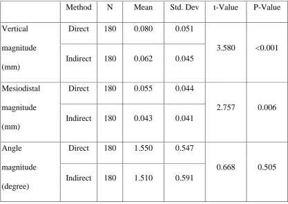
Table 1 shows the mean magnitude of deviation of direct and indirect method for all three variables. Statistically significant difference was noticed in vertical and mesiodistal positioning of brackets, with lesser deviation in indirect method. The deviation in angulation of bracket was not statistically significant.
Table 2 shows the deviation of direction of direct and indirect method for all the three variables. There was a statistically significant difference in the direction of deviation between direct and indirect method for vertical positioning with more tendency for gingival placement of brackets in direct method.
Deviation in first quadrants
Results
34
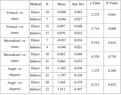
direct method. Both angle and mesiodistal position were not statistically significant. Table 7 shows that statistically significant difference exists between direct and indirect method in vertical positioning towards gingival direction with more gingival placement in direct method.
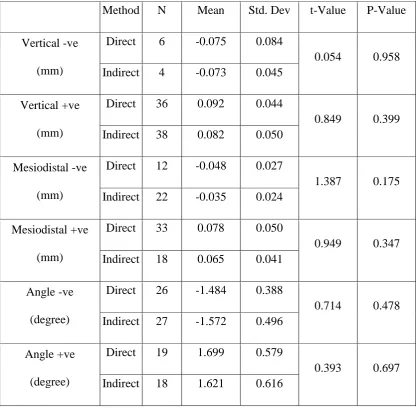
Deviation in second quadrants
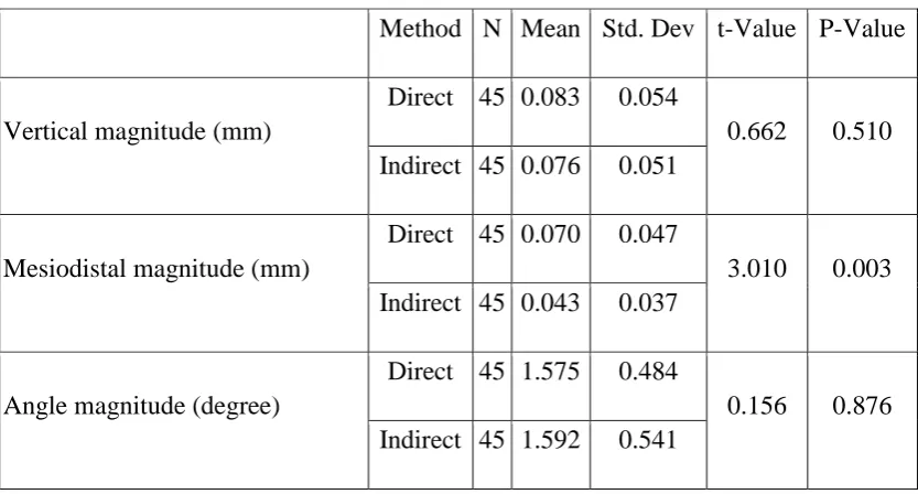
Table 4 shows that in second quadrant, the magnitude of mesiodistal deviation between direct and indirect method was statistically significant with higher magnitude of deviation in direct method.
Table 8 shows that there was no statistically significant difference between direct and indirect method in direction of placement in any of the three variables.
Deviation in third quadrants
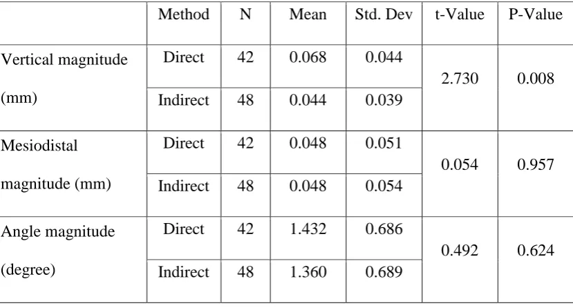
Table 5 shows that in third quadrant, the magnitude of vertical position between direct and indirect method was statistically significant with higher magnitude of deviation in direct method.
Table 9 shows that statistically significant difference between direct and indirect method in vertical position towards gingival direction with more gingival placement in direct method and mesiodistal position towards distal direction with more distal direction in direct method.
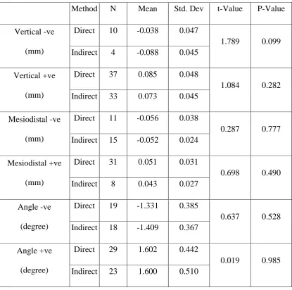
Deviation in fourth quadrants
Results
35
direct and indirect method was statistically significant with higher magnitude of difference in direct method.
Table 10 shows that there was no statistically significant difference between direct and indirect method in direction of placement in any of the three variables.
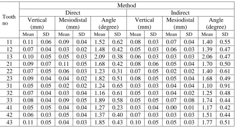
Deviation in tooth wise
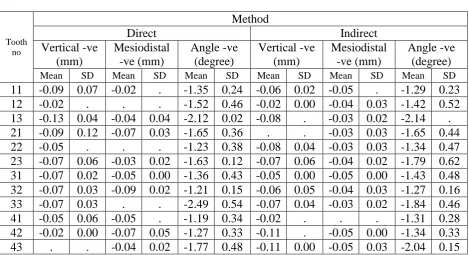
Table 12 shows tooth wise mean magnitude of deviation for all three variables. It shows higher magnitude of deviation in vertical positioning for all teeth except for left upper lateral incisor where the magnitude of deviation was same for both direct and indirect method. The deviation in mesiodistal position was less compared to vertical positioning. The mean deviation in mesiodistal position was lesser in magnitude for all teeth except for upper right lateral incisor and lower left central and lateral incisor where direct bonding showed less deviation. The mean deviation in angulation was relatively less in indirect method.
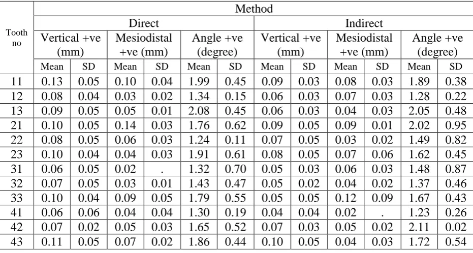
Table 13 shows tooth wise mean direction of deviations between Direct and Indirect methods in +ve direction. In vertical positioning, the direct method shows more amount of gingival deviation of brackets. In mesiodistal positioning and angulation the difference between direct and indirect method in +ve direction are less.
Results
[image:49.612.111.529.207.502.2]36
Table 1
Independent samples T-Test to compare the mean deviations between Direct and Indirect methods
Method N Mean Std. Dev t-Value P-Value Vertical
magnitude (mm)
Direct 180 0.080 0.051
3.580 <0.001 Indirect 180 0.062 0.045
Mesiodistal magnitude (mm)
Direct 180 0.055 0.044
2.757 0.006 Indirect 180 0.043 0.041
Angle magnitude (degree)
Direct 180 1.550 0.547
Results
37
Table 2
Independent samples T-Test to compare the mean deviations with direction between Direct and Indirect methods
Method N Mean Std. Dev t-Value P-Value
Vertical -ve (mm)
Direct 39 -0.069 0.056
0.543 0.589 Indirect 30 -0.062 0.038
Vertical +ve (mm)
Direct 135 0.087 0.047
3.203 0.002 Indirect 134 0.070 0.043
Mesiodistal -ve (mm)
Direct 39 -0.051 0.031
1.821 0.072 Indirect 58 -0.041 0.023
Mesiodistal +ve (mm)
Direct 122 0.066 0.045
0.246 0.806 Indirect 84 0.064 0.045
Angle -ve (degree)
Direct 81 -1.473 0.434
0.108 0.914 Indirect 83 -1.481 0.444
Angle +ve (degree)
Direct 95 1.682 0.534
Results
38
[image:51.612.109.531.217.440.2]Independent samples T-Test to compare the mean deviations between Direct and Indirect methods in each quadrant
Table 3
First quadrant (deviation in magnitude)
Method N Mean Std. Dev t-Value P-Value Vertical magnitude
(mm)
Direct 45 0.097 0.051
3.469 0.001 Indirect 45 0.065 0.034
Mesiodistal magnitude (mm)
Direct 45 0.058 0.040
0.610 0.543 Indirect 45 0.053 0.036
Angle magnitude (degree)
Direct 45 1.697 0.549
0.665 0.508 Indirect 45 1.618 0.580
Table 4
Second quadrant (deviation in magnitude)
Method N Mean Std. Dev t-Value P-Value
Vertical magnitude (mm)
Direct 45 0.083 0.054
0.662 0.510 Indirect 45 0.076 0.051
Mesiodistal magnitude (mm)
Direct 45 0.070 0.047
3.010 0.003 Indirect 45 0.043 0.037
Angle magnitude (degree)
Direct 45 1.575 0.484
[image:51.612.112.529.488.712.2]Results
[image:52.612.113.528.172.395.2]39
Table 5
Third quadrant (deviation in magnitude)
Method N Mean Std. Dev t-Value P-Value Vertical magnitude
(mm)
Direct 42 0.068 0.044
2.730 0.008 Indirect 48 0.044 0.039
Mesiodistal magnitude (mm)
Direct 42 0.048 0.051
0.054 0.957 Indirect 48 0.048 0.054
Angle magnitude (degree)
Direct 42 1.432 0.686
0.492 0.624 Indirect 48 1.360 0.689
Table 6
Fourth quadrant (deviation in magnitude)
Method N Mean Std. Dev t-Value P-Value Vertical magnitude
(mm)
Direct 48 0.073 0.052
0.739 0.462 Indirect 42 0.066 0.048
Mesiodistal magnitude (mm)
Direct 48 0.046 0.035
2.712 0.008 Indirect 42 0.027 0.031
Angle magnitude (degree)
Direct 48 1.495 0.438
[image:52.612.111.530.474.697.2]Results
40
[image:53.612.111.530.223.551.2]Independent samples T-Test to compare the mean deviations with directions between Direct and Indirect methods in each quadrant
Table 7
First quadrant (deviation in direction)
Method N Mean Std. Dev t-Value P-Value Vertical -ve
(mm)
Direct 10 -0.098 0.065
2.275 0.041 Indirect 7 -0.046 0.027
Vertical +ve (mm)
Direct 35 0.097 0.048
2.716 0.008 Indirect 37 0.070 0.033
Mesiodistal -ve (mm)
Direct 7 -0.033 0.034
0.516 0.614 Indirect 9 -0.040 0.021
Mesiodistal +ve (mm)
Direct 38 0.063 0.040
0.320 0.750 Indirect 31 0.066 0.033
Angle -ve (degree)
Direct 24 -1.562 0.436
1.275 0.209 Indirect 22 -1.397 0.438
Angle +ve (degree)
Direct 20 1.944 0.479
Results
[image:54.612.112.530.162.572.2]41
Table 8
Second quadrant (deviation in direction)
Method N Mean Std. Dev t-Value P-Value Vertical -ve
(mm)
Direct 6 -0.075 0.084
0.054 0.958 Indirect 4 -0.073 0.045
Vertical +ve (mm)
Direct 36 0.092 0.044
0.849 0.399 Indirect 38 0.082 0.050
Mesiodistal -ve (mm)
Direct 12 -0.048 0.027
1.387 0.175 Indirect 22 -0.035 0.024
Mesiodistal +ve (mm)
Direct 33 0.078 0.050
0.949 0.347 Indirect 18 0.065 0.041
Angle -ve (degree)
Direct 26 -1.484 0.388
0.714 0.478 Indirect 27 -1.572 0.496
Angle +ve (degree)
Direct 19 1.699 0.579
Results
42
Table 9
Third quadrant (deviation in direction)
Method N Mean Std. Dev t-Value P-Value Vertical -ve
(mm)
Direct 13 -0.066 0.023
0.499 0.622 Indirect 15 -0.060 0.039
Vertical +ve (mm)
Direct 27 0.073 0.049
2.298 0.026 Indirect 26 0.047 0.035
Mesiodistal -ve (mm)
Direct 9 -0.063 0.022
2.816 0.011 Indirect 12 -0.038 0.020
Mesiodistal +ve (mm)
Direct 20 0.073 0.056
0.271 0.788 Indirect 27 0.068 0.061
Angle -ve (degree)
Direct 12 -1.498 0.577
0.119 0.906 Indirect 16 -1.521 0.443
Angle +ve (degree)
Direct 27 1.561 0.588
Results
43
Table 10
Fourth quadrant (deviation in direction)
Method N Mean Std. Dev t-Value P-Value Vertical -ve
(mm)
Direct 10 -0.038 0.047
1.789 0.099 Indirect 4 -0.088 0.045
Vertical +ve (mm)
Direct 37 0.085 0.048
1.084 0.282 Indirect 33 0.073 0.045
Mesiodistal -ve (mm)
Direct 11 -0.056 0.038
0.287 0.777 Indirect 15 -0.052 0.024
Mesiodistal +ve (mm)
Direct 31 0.051 0.031
0.698 0.490 Indirect 8 0.043 0.027
Angle -ve (degree)
Direct 19 -1.331 0.385
0.637 0.528 Indirect 18 -1.409 0.367
Angle +ve (degree)
Direct 29 1.602 0.442
[image:56.612.113.529.170.582.2]Results
[image:57.612.111.528.148.562.2]44
Table 11
Proportions of values showing the direction of deviations Quadrant
Total First Second Third Fourth
N % N % N % N % N %
Vertical Count
Equal 1 1.1 6 6.7 9 10.0 6 6.7 22 6.1 Negative 17 18.9 10 11.1 28 31.1 14 15.6 69 19.2 Positive 72 80.0 74 82.2 53 58.9 70 77.8 269 74.7
Mesiodistal Count
Equal 5 5.6 5 5.6 22 24.4 25 27.8 57 15.8 Negative 16 17.8 34 37.8 21 23.3 26 28.9 97 26.9 Positive 69 76.7 51 56.7 47 52.2 39 43.3 206 57.2
Angle Count
Results
[image:58.612.107.576.219.472.2]45
Table 12
The mean magnitude of deviations between Direct and Indirect methods Tooth wise
Tooth no
Method
Direct Indirect
Vertical (mm) Mesiodistal (mm) Angle (degree) Vertical (mm) Mesiodistal (mm) Angle (degree)
Mean SD Mean SD Mean SD Mean SD Mean SD Mean SD
Results
[image:59.612.113.579.235.484.2]46
Table 13
The mean direction of deviations between Direct and Indirect methods Tooth wise
+ve direction
Tooth no
Method
Direct Indirect
Vertical +ve (mm) Mesiodistal +ve (mm) Angle +ve (degree) Vertical +ve (mm) Mesiodistal +ve (mm) Angle +ve (degree)
Mean SD Mean SD Mean SD Mean SD Mean SD Mean SD
Results
[image:60.612.113.583.197.452.2]47
Table 14
The mean direction of deviations between Direct and Indirect methods Tooth wise
-ve direction
Tooth no
Method
Direct Indirect
Vertical -ve (mm) Mesiodistal -ve (mm) Angle -ve (degree) Vertical -ve (mm) Mesiodistal -ve (mm) Angle -ve (degree)
Mean SD Mean SD Mean SD Mean SD Mean SD Mean SD
Results
48 0.000 0.010 0.020 0.030 0.040 0.050 0.060 0.070 0.080 0.090 0.100 Direct Indirect 0.080 0.062 M e a n v a lueMean Vertical deviation (mm)
0.000 0.010 0.020 0.030 0.040 0.050 0.060 0.070 0.080 0.090 0.100 Direct Indirect 0.055 0.043 M e a n v a lue
Results
49 0.000
0.250 0.500 0.750 1.000 1.250 1.500 1.750 2.000
Direct Indirect
1.550 1.510
M
e
a
n
v
a
lue
Results
50 0.00 0.01 0.02 0.03 0.04 0.05 0.06 0.07 0.08 0.09 0.101st 2nd 3rd 4th
0.097 0.092 0.073 0.085 0.098 0.075 0.066 0.038 M ea n v alue Quadrant
Vertical (mm) - Direct Positive Negative 0.00 0.01 0.02 0.03 0.04 0.05 0.06 0.07 0.08 0.09 0.10
1st 2nd 3rd 4th
0.070 0.082 0.047 0.073 0.046 0.073 0.060 0.088 M ea n v alue Quadrant
Results
51 0.00 0.01 0.02 0.03 0.04 0.05 0.06 0.07 0.08 0.09 0.101st 2nd 3rd 4th
0.063 0.078 0.073 0.051 0.033 0.048 0.063 0.056 Mea n v alue Quadrant
Mesiodistal (mm) - Direct Positive Negative 0.00 0.01 0.02 0.03 0.04 0.05 0.06 0.07 0.08 0.09 0.10
1st 2nd 3rd 4th
0.066 0.065 0.068
0.043 0.040
0.035 0.038
0.052 Mea n v alue Quadrant
Results
52 0.00 0.25 0.50 0.75 1.00 1.25 1.50 1.75 2.001st 2nd 3rd 4th
1.944
1.699
1.561 1.602
1.562
1.484 1.498
1.331 Mea n v alue Quadrant
Angle (degree) - Direct Positive Negative 0.00 0.25 0.50 0.75 1.00 1.25 1.50 1.75 2.00
1st 2nd 3rd 4th
1.911
1.621
1.517 1.600
1.397
1.572 1.521
1.409 Mea n v alue Quadrant
53
DISCUSSION
Fixed orthodontic appliances from their inception have been refined to the
present state. Initial fixed orthodontic appliances had their brackets welded on
to metal bands and cemented over teeth surface. With the introduction of acid
etching technique by Michel Buonocore36 in 1955, the possibility of direct
placement of brackets on the enamel surface evolved. In 1965 George
Newman22 described the technique to directly place the brackets on tooth’s
surface with 40% phosphoric acid for enamel conditioning and polyamide
cured epoxy resin.
Direct bonding of brackets on to a tooth surface emerged to claim significant
advantages over banding the brackets on teeth like, (1) less consumption of
chair side time, reducing patient’s visits for bracket placement, (2) easy clean
up, reducing risk of enamel demineralisation, (3) more comfort for the
patients, increasing patient compliance (4) lesser consumption of operator’s
energy, increasing clinician’s efficiency (5) improved precision of bracket
placement on teeth surface. These advantages made the direct bonding of
brackets popular.
In 1972, Silverman and Cohen19 described a method of universal direct
bonding system from which the indirect bonding technique evolved. This
technique was further modified by Royce G. Thomas49 in the year 1979 to
54
composite coating of bracket bases was done with light cure composite. The
advantages of this pre coating are, (1) light cure composite allows sufficient
time for the operator to place the brackets in precise position before curing (2)
consistency of bracket placement and, (3) differences in bucco lingual
thickness of the teeth can be compensated34.
From introduction of this indirect bonding technique several modifications
have been introduced, in terms of materials used for positioning brackets on
working models, transfer tray fabrication and bonding adhesives. The
advantages of indirect bonding technique claimed over direct bonding are, (1)
more accurate bracket placement (2) less chair time (3) better ergonomics for
operator (4) reduced need for direct visualization during bonding. The
disadvantages quoted are, (1) higher laboratory cost (2) operator sensitive (3)
difficulty in removal of excess bonding adhesive from teeth surface (5)
bracket bases not entirely filled with bonding adhesives and, (6) increased
thickness of adhesive on bracket base. Though it was logical to say that the
bracket placement can be more precise on the handheld, completely
accessible, dry models, the studies to strengthen the claim of high precision in
bracket positioning are very few.
Bon chan koo et al13 conducted a study on mannequins to compare the
accuracy between direct and indirect bonding methods and concluded that
indirect bonding was better in vertical bracket placement but mesiodistal and
55
study in clinical situation and concluded that the mean error in vertical plane
was more than mesiodistal plane and mean bracket error was similar to both
techniques. Thus contradicting the previous view regarding accuracy of
bracket positioning. Bjorn U. Zacrisson et al14 opined that for clinical
purposes, no obvious difference could be appreciated in bracket placement
between the indirect and direct techniques, with the possible exception of few
posterior teeth in difficult positions and that with some experience, it might be
possible to position the brackets precisely even with direct bonding approach.
In this study, Sondhi rapid set4, the resin developed by Anoop sondhi in 1999
was used to position the brackets on teeth surface. The viscosity of the resin
was relatively less than any other conventional bonding resin. This property is
said to fill the micro defects in the preformed composite bracket bases used in
this study. Though the viscosity of the resin was reduced, Arndt klocke et al8
showed that the shear bond strength of this resin with pre coated bracket base
was comparable with any other resin used for indirect bonding technique. The
resin is chemically cured hence avoids the necessity of clear transfer tray for
light permission in case of light cure resin. The main advantage of this resin is
its quick setting time of 30 seconds which allows removing the transfer tray in
30 seconds. The dual layer transfer tray was prepared, which provided rigid
outer tray to ease the placement of tray without distortion and flexible inner
56
The magnification of image in the photograph were standardized to be same
throughout the study with a custom fabricated jig that was attached to the
camera. Bon chan koo et al13 have examined the accuracy by superimposing
the hand traced images on acetate paper. In our study to minimise human
error, software was used for superimposition and measuring the accuracy of
bracket placement. Hodge et al55 have traced the outline of crown and bracket
tie wings manually. Wendel et al10 conducted an in vitro study and used a new
transfer device, Aptus bonding device to transfer the brackets. They used three
dimensional measurements on the working and plaster models using 3D laser
scan to measure the accuracy of bracket positioning.
In this study, we have located the magnitude and direction of error separately
without combining the +ve and –ve values between direct and indirect
bonding in tooth and quadrant wise.
Vertical positioning of brackets influences the final vertical positioning of
teeth; horizontal position influences the rotational tendency of teeth;
angulation influences the mesiodistal tip of teeth. So to achieve the desired
final position of teeth, these three positions of brackets must be precise. In this
study the precise placement of brackets between direct and indirect techniques
was examined by comparing the three variables namely, vertical positioning,
mesio-distal positioning and angulations of brackets.
The results in this study reveal significant magnitude of deviation in vertical
57
with greater magnitude of deviation in vertical positioning. Though the
magnitude of deviation for vertical position is higher for both direct and
indirect method than the other two variables, the direct method shows higher
magnitude of deviation. This may be due to the relatively long inciso-gingival
plane of tooth. The mesiodistal deviations were relatively less for all samples.
This may be due to t