promoting access to White Rose research papers
White Rose Research Online eprints@whiterose.ac.uk
Universities of Leeds, Sheffield and York
http://eprints.whiterose.ac.uk/
This is an author produced version of a paper published inVDI Berichte.
White Rose Research Online URL for this paper:
http://eprints.whiterose.ac.uk/9084/
Published paper
VALVE RECESSION: FROM EXPERIMENT TO PREDICTIVE MODEL
Roger Lewis*1, Rob Dwyer-Joyce1, Alan Brooks2, Thomas Slatter1 1
Department of Mechanical Engineering, The University of Sheffield, Mappin Street, S1 3JD, UK.
2
Ford Motor Company Limited, Diesel Engine Engineering, Room 5 / 01A-H02-D, Dagenham Diesel Centre, Dagenham, Essex, RM9 6SA, UK.
*Corresponding author
Abstract
Increasing demands on engine performance and cost reductions have meant that
advances made in materials and production technology are often outpaced This
frequently results in wear problems occurring with engine components. Few models
exist for predicting wear, and consequently each wear problem has to be
investigated, the cause isolated and remedial action taken. The objective of this
work was to carry out experimental studies to investigate valve and seat insert wear
mechanisms and use the test results to develop a recession prediction tool to
assess the potential for valve recession and solve problems that occur more quickly.
Experimental apparatus has been developed that is capable of providing a valid
simulation of the wear of diesel automotive inlet valves and seats. Test
methodologies developed have isolated the effects of impact and sliding.
A semi-empirical wear model for predicting valve recession has been developed
based on data gathered during the bench testing. A software program, RECESS,
was developed to run the model. Model predictions are compared with engine
dynamometer tests and bench tests. The model can be used to give a quantitative
prediction of the valve recession to be expected with a particular material pair or a
qualitative assessment of how parameters need to be altered in order to reduce
recession.
The valve recession model can be integrated into an industrial environment in order
to help reduce costs and timescales involved in solving valve/seat wear problems.
Introduction
As a result of demands for increased engine performance and design changes to
seat inserts continues to cause problems. This is despite advances in valve and seat
materials and production techniques.
The drive for reduced oil consumption and exhaust emissions, the phasing out of
leaded petrol, reductions in the sulphur content of diesel fuel and the introduction of
alternative fuels such as gas also have implications for valve and seat wear.
At present no models exist that can be used to quantify valve or seat life. Each
valve/seat wear problem that arises, therefore, has to be investigated, the cause of
the problem isolated and remedial action taken. This is an expensive and time
consuming process and is difficult to fit in with the ever-decreasing lead-times being
used in engine development programmes.
A long-term approach is required in order to understand fundamental wear
mechanisms and the effect of varying engine operating conditions or design
changes to the valve train. This information can then be used to develop tools for
predicting wear and for solving problems more quickly if they do occur.
The objective of this work was therefore to investigate valve and seat wear
mechanisms using specially design bench test apparatus and to use the results,
along with data collected during a review of literature and failure analysis of actual
valves and seats, to develop a recession prediction tool for use in industry.
Valve and Seat Insert Wear Testing
Two laboratory based test methods (hydraulic component loading apparatus and
motorised cylinder-heads) capable of providing a valid simulation of the wear of
diesel automotive inlet valves and seats have been developed [1, 2]. These were
used in the course of bench test work to investigate the fundamental wear
mechanisms and the effect of critical engine operating parameters.
The first rig, shown in Figure 1, is designed to be mounted in a hydraulic fatigue test
machine. It is able to simulate both combustion loading and impact of the valve on
the seat on valve closure. Test methodologies developed have isolated the effects of
HOT AIR SUPPLY
THRUST BEARING
SEAT INSERT
VALVE
SEAT INSERT HOLDER
SPRING (OPENS VALVE)
BRONZE BUSHES CYCLIC LOADING APPLIED USING HYDRAULIC ACTUATOR
[image:4.595.173.418.70.267.2]PULLEY AND BELT SYSTEM TO ROTATE VALVE VALVE COLLET
Figure 1. Hydraulic Loading Test-Rig
Two motorised cylinder-head rigs have been built (as shown in Figure 2): one based
on a 1.8 litre diesel engine with direct acting cam and follower arrangement and the
second on a 2.5 litre diesel engine, which uses rocker arms. These can be used to
investigate impact wear of valve and seats over a range of closing velocities.
Figure 2. Motorised Cylinder-Head Test-Rigs (a) 1.8 litre diesel and (b) 2.5 litre diesel
Valve Wear Mechanisms
Investigations carried out using the test-rigs have shown that the diesel engine inlet
valve and seat insert wear problem involves two distinct mechanisms [1, 3]:
Impact as the valve strikes the seat on closure.
[image:4.595.87.514.424.593.2] Micro-sliding at the valve/seat interface caused by elastic deformation of the valve head and engine block as it is pressed into the seat by the combustion
pressure.
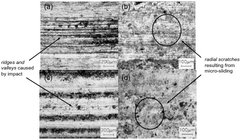
Impact on valve closure causes plastic deformation of the seating face surface,
which leads to the formation of a series of ridges and valleys circumferentially
around the axis of the valve seating face [1, 4]. It also leads to surface cracking and
subsequent material loss from seat inserts at high closing velocities [2]. Sliding
causes the formation of radial scratches on the seat insert seating faces [1, 4].
Figure 3 illustrates these wear features, and compares valves and seats from
hydraulic loading apparatus tests with those from dynamometer engine tests to
[image:5.595.61.542.310.588.2]indicate the validity of the test methodologies developed.
Figure 3. Laboratory Tested Valve (a) and Seat Insert (b) Compared with Engine Tested Valve (c) and Seat Insert (d)
Effect on Wear of Engine Operating Parameters
The prevailing wear mechanisms have been shown to be more severe when critical
operating parameters such as valve closing velocity, combustion load and valve
misalignment relative to the seat insert are increased, as shown in Figure 4 [3].
(a)
(b)
(c)
(d)
ridges and valleys caused by impact
radial scratches
Increasing the combustion loading caused a greater amount of sliding at the
valve/seat interface. Raising the valve closing velocity caused an increase in impact
wear. Surface cracking and subsequent material loss was prevalent on seats and
greater plastic deformation on the valve seating faces was observed. Recession was
found to be approximately proportional to the square of the closing velocity (i.e. the
valve kinetic energy on closing). Misalignment of the valve caused the valve wear
scar widths at the point of contact to increase significantly, leading to increased
sliding and hence greater wear.
0 0.05 0.1 0.15 0.2
0 2000 4000
Valve Closing Velocity (mm/s)
V a lve R e ce ssi o n ( m m ) 0 0.01 0.02 0.03 0.04 0.05
6 13 18.5 Combustion Load (kN)
V a lv e R e ce ssi o n ( m m ) 0 0.01 0.02 0.03 0 0.25
Valve Misalignment (mm)
[image:6.595.88.520.256.380.2]V a lve R e ce ssi o n ( m m )
Figure 4. Valve Recession with Cast Tool Steel Seat Inserts for Increasing (a) Valve Closing Velocity (after 100 000 cycles); (b) Combustion Load (after 25000 cycles)
and (c) Radial Valve Misalignment (relative to seat position) (after 25000 cycles)
Valve rotation ensured even wear and promoted debris removal from the valve/seat
interface. This is useful in reducing abrasive wear and the build-up of deposits and
subsequent hot spots.
Valve Recession Modelling
Development of the Model
In developing the model it was decided to consider the impact and micro-sliding
wear mechanisms separately as they occur as two independent events in the valve
operating cycle. Approaches for modelling the wear mechanisms were identified and
parameters were then derived either directly from the valve and seat design and
engine operating conditions or from bench test results. An allowance for effects such
as misalignment and variation in lubrication were also built in. The two parts were
then combined to form the final valve recession model.
Sliding Wear Calculation
An Archard type wear law [5] was used for modelling the sliding wear component:
h x kP
V c (1)
The wear volume, V, is proportional to the contact force, Pc (N), the sliding distance,
x (m) and the penetration hardness of the wearing surface, h (N/m2). The
non-dimensional wear coefficient, k, is determined empirically.
The peak load normal to the direction of sliding at the valve/seat interface, Pc, was
calculated using the peak combustion pressure, pp, and the valve head geometry:
vv p c
R p P
sin 1
2
(2)
where v is the valve seating face angle () and is the coefficient of friction at the
valve/seat interface. The load on the valve seat during a combustion cycle is initially
zero then rises to Pc and falls back down to zero. For the purposes of calculating the
sliding wear volume an average load, P, was assumed equal to half Pc. In the
absence of other data was estimated to be 0.1 for the valve/seat interface, which
is a typical value for boundary lubricated steel surfaces.
Data generated for slip at the interface by Mathis et al. [6] using finite element
analysis was used in this model. It was assumed that slip at the interface, , is
proportional to combustion load Pc. The total sliding distance is calculated by
multiplying the slip, , by the number of loading cycles, N.
Wear coefficients were taken from data generated for sliding metals by Rabinowicz
[7]. These were derived for different material pairings and states of lubrication using
Equation 1. The lubrication states for the valve/seat insert material pairings used in
this study are shown in Table 1 as well as the wear coefficients taken.
Impact Wear Calculation
The deformation observed on the valve seating faces and surface cracking on the
seat inserts observed during bench tests on the motorised cylinder-heads are
characteristic of wear features attributed to processes leading to wear by single or
multiple impact of particles [8]. It was therefore decided to use a relationship of the
same form as that used in erosion studies to model wear mass, W, due to the
impact of the valve on the seat during valve closure:
n
KNe
W (3)
where e is the impact energy per cycle (J) (given by mv2/2, where m is mass of valve
and follower added to half the mass of valve spring (Kg) and v is the valve velocity at
impact (m/s)), and K and n are empirically determined wear constants.
Valve closing velocities are derived from valve lift curves for the engine under
consideration. The closing velocity is taken as that at the initial valve clearance, ci.
As the valve recesses the valve clearance at closure will decrease thereby
decreasing the valve closing velocity. This is considered in the application of the
model.
Values of K and n for the seat materials used in these studies were derived using an
iterative process to fit Equation 3 to experimental data from motorised cylinder-head
tests. Equation 3 was used to calculate wear volumes rather than wear mass to fit in with Archard’s sliding wear equation (Equation 1) when combining the two to create
the final model. These were then used to calculate recession values using equations
derived from the seat geometry. At each data point the velocity was recalculated to
take account of the change in lift due to recession. The results of this process for
tests run with a cast seat insert in the 1.8 litre diesel engine cylinder-head rig (based
0 20 40 60 80 100 120 140 160
[image:9.595.137.457.75.274.2]Number of Cy cles x1000 0 0.02 0.04 0.06 0.08 0.1 0.12 0.14 0.16 Va lve Re c essi on (mm ) 3680mm/s 1600mm/s 324mm/s
Figure 5. Modelling of Valve Recession for Three Different Closing Velocities on the
1.8 litre Motorised Cylinder-Head (data points - experimental data, broken line -
model prediction)
As can be seen, the values of K and n derived give good correlation over a range of
velocities. The values of K and n for sintered (also based on a tool steel matrix) and
cast insert materials are listed in Table 1.
Recession Calculation
The equations for sliding and impact wear (1 and 3) were put together to give the
final wear model. In order to incorporate the change in pressure at the interface and
any other effects likely to lead to a reduction in the wear rate with time, such as work
hardening, a term consisting of the ratio of the initial valve/seat contact area, Ai, to
the contact area after N cycles, A, to the power of a constant j was included. j was
determined empirically using bench and engine test data.
j i n A A KNe h N P k V
(4)
Equation 4 gives a wear volume, which is then converted to a recession value, r,
using equations derived from the seat geometry. Equation 5 gives r in terms of V for
s i i s s i w w R V r
cos sin sin
2 (5)
where Ri is the initial seat insert radius, s is the seat insert seating face angle and wi
is the initial seat insert seating face width (as measured). Ri can be calculated using
wi and the radius and seating face width as specified for the seat insert (Rd and wd),
as shown in Figure 6.
Ri Rd
Wd
Wi
[image:10.595.234.359.217.327.2]s
Figure 6. Calculation of Initial Seat Insert Radius
Implementation of the Model
A flow chart outlining the use of the model is shown in Figure 7. The wear volume is
determined incrementally. The initial valve closing velocity and contact area are used
to calculate the volume of material removed over the first N cycles. This is then
converted to recession and new values for the clearance (and hence closing
velocity) and contact area are determined. The calculation is repeated until the total
number of iterated cycles equals the required run duration.
IMPACT WEAR VOLUME
= KNen
SLIDING WEAR VOLUME
=k P N
h ci N K n v
= f(c)
m
= 1mv2 2
e
k
h
Wear Volume
For N Cycles Add to TotalVolume
Calculate Recession = f(V) Recalculate v
= f(c)
Recalculate c
= ci - r
+ x A Ai j P N
[image:10.595.118.482.550.747.2]In order to provide a tool for running the valve wear model, an iterative software
programme called RECESS was developed. Within the programme the recession
calculation is carried out in three stages. In the first and second the sliding and
impact wear volumes, Vs and Vi, are calculated for N cycles. In the final stage, Vs
and Vi are added together to calculate the wear volume for the set of N cycles. This
is then used to calculate the recession value, r, for the total number of cycles.
RECESS has now been developed into a location independent design tool. A
version has been created to operate within the MatLab environment (see Figure 8)
and also as a Java applet. A website has been developed to provide a portal to the
valve wear prediction software (see Figure 9), which means that RECESS could be
[image:11.595.163.432.312.442.2]used from anywhere in the world.
Figure 8. RECESS MatLab Tool
[image:11.595.100.496.507.740.2]Validation of the Model
In order to validate the model, valve recession predictions for 1.8 litre diesel engine
inlet valves were calculated for engine tests using two different seat insert materials;
a cast and sintered tool steel. Initial conditions used for the engine tests are shown
in Table 1.
Figure 10 shows the model prediction for engine tests run using cast and sintered
inserts. As can be seen, the model produces a good prediction of valve recession.
Looking at the contribution of the two mechanisms to the overall wear it was evident
that impact wear was greater (about 70% of total).
0 20 40 60 80 100 120 140
Test Duration (Hours) 0
0.05 0.1 0.15 0.2 0.25 0.3 0.35
V
a
lve
R
ecess
ion (
mm) Sintered Seat Insert
Model Prediction Sintered Seat Insert
Engine Test
Cast Seat Insert Engine Test
[image:12.595.128.468.283.511.2]Cast Seat Insert Model Prediction
Figure 10. Model Predictions versus Engine Test Data
Model simulations were also carried out for the hydraulic loading apparatus tests for
the cast and sintered materials seat inserts with a dry contact and a lubricated cast
insert, where a different value was used for the value of k, the sliding wear
0 20 40 60 80 100 120
[image:13.595.109.486.78.312.2]Number of Cy cles x1000 0 0.005 0.01 0.015 0.02 0.025 0.03 V a lv e R e c e s s io n ( m m) Sintered Seat Insert Cast Seat Insert Lubricated Cast Seat Insert
Figure 11. Model Predictions Versus Hydraulic Loading Apparatus Data for a Sintered Seat Insert, a Cast Seat Insert and a Lubricated Cast Seat Insert
Table 1. Inputs and Typical Outputs for the 1.8L Diesel Engine Test Recession Predictions
Seat Material Cast Sintered
Lubrication State Poor Poor
Sliding Wear Coefficient, k 510-5 510-5
Impact Wear Constant, K 5.310-14 3.510-14
Impact Wear Constant, n 1 0.3
Initial Seat Insert Facing Width, wi (mm) 2 2
Initial Seat Insert Radius, Ri (mm) 16.85 16.85
Initial Seating Face Area, Ai (mm
2
) 211.7 211.7
Valve Head Radius, Rv (mm) 18 18
Seating Face Angle,v () 45 45
Coeff. of Friction at Interface, 0.1 0.1
Seat Hardness, h (Hv) 490 490
Max. Combustion Pressure, pp (MPa) 13 13
Avg. Contact Force at Interface,P (N) 8053 8053
Slip at Interface, , (m) 5.24 5.24
Valve Closing Velocity, v (mm/s) 288 288
Wear Constant, j 10 10
Number of Cycles 18.72106 144106
Total Wear Volume (mm3) 0.0087 0.0289
Recession, r (mm) 0.057 0.266
Seat Insert Radius (mm) 16.9 17.1
Seat Insert Seating Face Width, w (mm) 2.08 2.26
Seating Face Area, A (mm2) 221.0 241.5
[image:13.595.103.495.423.728.2]Application of the Model
It has been shown that the valve recession model produces good quantitative
predictions of valve recession for engine tests and other work has shown that good
correlation exists with bench test results [2]. It could clearly be used, therefore, to
give a quick assessment of the valve recession to be expected with a particular
material pair under a particular set of engine/test-rig operating conditions. This will
help speed up the process undertaken in selecting material combinations or in
choosing engine operating parameters to give the least recession with a particular
combination. It can also be used to give a qualitative assessment of how wear can
be reduced by varying engine operating parameters and material properties.
By studying the individual contributions of impact and sliding wear it is possible to
focus on the particular parameters that need to be altered in order to produce the
largest reduction possible in the total wear for a particular material combination.
A new long-term approach to combating valve recession is now possible. As new
engine design changes are made, the prototype valve train systems are typically
modelled in multi-body simulation packages. The output from these (loads and
deformations) could be used as inputs to RECESS to predict recession rates for a
given design. In this way it may be possible to design out the causes of valve
recession.
Conclusions
Experimental apparatus has been used to isolate the wear mechanisms leading to
valve and seat insert wear, which are caused by impact of the valve on the seat and
micro-sliding during combustion in the cylinder. The key engine operating
parameters affecting wear have been identified as valve closing velocity, valve
misalignment and combustion loading.
A valve recession prediction tool has been developed using the results of the
experimental bench testing to be used in industry to assess the potential for valve
recession during the development of new engines or in making design changes or
changes in valvetrain dynamics and materials selection in existing engines to reduce
wear model, which combines existing models for the mechanisms of wear observed
(impact and sliding). Constants required for the model were taken from curves fitted
to experimental data.
The model provides a good approximation of valve recession for both engine tests
and tests run on the hydraulic loading apparatus. Modelling of diesel engine tests
indicated that impact was the major cause of valve recession.
The model can be used to give a quantitative prediction of the valve recession to be
expected with a particular material pairing under a known set of engine/test-rig
operating conditions. This will speed up the process undertaken in selecting material
combinations or in choosing engine operating parameters to give the least
recession. It can also be used to give a qualitative assessment of how wear can be
reduced by varying engine operating parameters and material properties. For
example, reducing valve closing velocity, valve mass and valve seating face angle or
increasing the valve head stiffness and seat material hardness will reduce valve
recession.
Software called RECESS has been written to run the prediction model. This is
available as a location independent design tool. A version has been created to
operate within the MatLab environment and also as a Java applet. A website has
been developed to provide a portal to the valve wear prediction software, which
means that RECESS could be used from anywhere in the world.
Acknowledgements
The authors gratefully acknowledge the financial support of the Ford Motor
Company and the help and support of Alan Brooks of the Diesel Engines Group.
References
[1] Lewis, R., Dwyer-Joyce, R.S., Josey, G.: Design and Development of a
Bench Test-Rig for Investigating Diesel Engine Inlet Valve and Seat Wear.
[2] Lewis, R., Dwyer-Joyce, R.S.: An Experimental Approach to Solving Valve
and Seat Insert Wear Problems. Proceedings of the 27th Leeds-Lyon
Symposium on Tribology, Lyon (2000) pp. 629-640.
[3] Lewis, R., Dwyer-Joyce, R.S., Josey, G.: Investigation of Wear Mechanisms
Occurring in Passenger Car Diesel Engine Inlet Valves and Seat Inserts. SAE
paper 1999-01-1216 (1999).
[4] Van Dissel, R., Barber, G.C., Larson, J.M., Narasimhan, S.L.: Engine Valve
Seat and Insert Wear. SAE Paper 892146 (1989).
[5] Archard, J.F.: Contact and Rubbing of Flat Surfaces. Journal of Applied
Physics 24, (1953) pp. 981-988.
[6] Mathis, R.J., Burrahm, R.W., Ariga, S., Brown, R.D.: Gas Engine Durability
Improvement. Paper GRI-90/0049, Gas Research Institute (1989).
[7] Rabinowicz, E.: The Wear Coefficient - Magnitude, Scatter, Uses. ASME
Paper 80-C2/LUB-4, Journal of Lubrication Technology - Transactions of the
ASME. 103, (1981) pp. 188-194.
[8] Zum-Gahr, K.H.: Microstructure and Wear of Materials. “Tribology” Series No.