Article
An Analysis of Seismic Behavior of Two
Non-coplanar Tunnels
Sina Pourzahedi
1,a,*
and Iman Aghayan
2,b1 Department of Civil Engineering, Islamic Azad University, Shahrood Branch, Shahrood, Iran 2 Department of Civil Engineering, Shahrood University of Technology, Shahrood, Iran
Email: a[email protected] (Corresponding author), b[email protected]
Abstract. With regard to increase in growth of population in metropolitan areas around
the world, the development of urban infrastructures in a way that is responsive to the population has become a major concern. Today, many cities are willing to use rail transport system which this requires conducting detailed studies of engineers in the field of traffic engineering for the optimal locating in rail lines. Hence in the field of structural and geotechnical engineering for detailed design and structure analysis of tunnels due to applied loads on it and their behavior against the vibrations generated by train movement or earthquake. Then, in order to achieve more realistic results, the urgent need to use dimensional analyses and non-linear models can be seen. In the present study, three-dimensional analysis of vibrations caused by simultaneous passing of two trains over each other in two tunnels with different directions, three-dimensional analysis of land subsidence caused by excavation of two passing tunnels and three-dimensional seismic analysis of two passing tunnels were discussed with the help of non-linear dynamic modeling. The results of this research showed although the soil at the bottom of the upper tunnel was on the verge of shear failure; however, the relative displacement of tunnels to each other was less than 10 mm. Moreover, the geometry section deformation of tunnels was around 0.8 mm which was negligible values. Thus, the studied tunnels had considerable stability.
Keywords: Land subsidence, non-coplanar tunnel, seismic behavior, three-dimensional
analysis, vibrations.
ENGINEERING JOURNAL Volume 21 Issue 2
1.
Introduction
The vibration analysis of tunnels and surrounding grounds due to train movement had very little significance in the past because of locating tunnels in mountains and deserts and only a series of simplified assumptions and equivalent static loads were used for seismic design of tunnels. The BART system was one of the first structures of underground that was designed for seismic loads [1] and during Loma Prieta earthquake in 1989 spared from any damage. For the first time in 1960 British Petroleum engineers have done the seismic design of underground spaces for a tunnel project. One of the first people who examined the effect of earthquakes on underground structures is Newmark who proposed an easy way to calculate the effect of earthquake loads on long tunnels and calculate the relative strains of underground tubes in1968. Keusel in 1969 devised a simple method for calculation of forces induced by earthquake on the linear tunnels that it has become the basis of many researches. Douglas and Warshaw (1971) offered the analysis results of the design of covered tunnel under the earthquake effect [2] .Dowding and Rozen examined the tunnel’s response to the ground movements. Their studies on the rock tunnels showed that tunnels were much safer than aboveground structures for a given intensity of vibration. It was also shown that the deep tunnels were safer than shallow tunnels [3]. Owen and Scholl declared that duration of earthquake was an important factor in the severity of damage to underground structures and can be increased with the continuity of stresses returning on the previously damaged parts.The initial damages will increase by earth movements such as fault and landslide [4]. John and Zahrah have presented a research paper in the field of long circular tunnels design against earthquake [5]. Sharma and Judd collected qualitative data for 192 reported visits from 85 earthquakes around the world. The available information show more damages for built facilities in soil relative to appropriate rock [6]. Keusel et al. in 1996 offered a simple way about the analysis and design of linear tunnels [7]. With the review of the seismic behavior and design of underground structures in soft grounds, Kawashima in 1999 suggested the seismic deformation method in these situations in which conducted the seismic analysis with applying deformation on the tunnel which its behavior was assumed identical [8]. Chen et al. in 2012 examined the mechanisms of seismic damages on the tunnels with different depths and observed that surface tunnels in loose rocks and deep tunnels in resistant rocks were extremely vulnerable [9]. Wang and Zhang carried out the seismic damage classification and the risk assessment of occurring earthquake on mountain tunnels and offered a new method to this aim using seismic parameters, ground conditions and structural data [10]. Shen et al. investigated the seismic damage mechanism and the dynamic deformation analysis of 52 mountain tunnels after the Wenchuan earthquake in 2008 and observed that mainly the relative deformations occurred in the upper half of the tunnels was more than the values of the lower sections [11]. Abdel-Motaal et al. examined the seismic interaction between the tunnels with a diameter ranging from 6 to 10 meters and surrounding granular soil. Moreover, the impact of the earthquake magnitude and dimensions of tunnels on existing damage was investigated. Based on the obtained results, they declared that the seismic analysis was only necessary for areas with seismic acceleration more than 0.15 g [12]. Gomes et al. studied the seismic behavior of shallow circular tunnels in two-layered ground [13]. In another research, Pitilakis et al. interaction effects, focusing on the tunnel response. The problem is investigated in the transversal direction, by means of full dynamic time history analyses. The results show that the presence of the aboveground structures may have a significant effect on the seismic response of the tunnel, especially when the latter is stiff and located in shallow depths [14]. Chen and Shen also have clarified the mechanism of isolation layer on shock absorption, which is proved to be an effective method to improve the safety of tunnel against earthquake [15]. In another study, new damage classification criterion to classify and quantify tunnel damage based on data collected from major earthquakes. Seismic risk assessment of tunnels is important for an effective disaster management plan. A risk-based assessment technique is proposed as a way to quantify the seismic risk of tunnels [16]. In this research, they examined the behavior of tunnels in the grounds with a layer of sand located on a layer of clay with different strength parameters and declared that heterogeneity of the ground in which the tunnel was buried had significant effect on the seismic behavior. Accordingly, this study compared with the previous studies conducted in the field of seismic design of tunnels has the following advantages.
1) The analysis of vibrations caused by simultaneously passing of two trains in two passing tunnels with different directions over each other.
With the progresses made in engineering sciences, public attitudes of designers is changing from the design based on the stress criteria toward the design based on the structure performance. Therefore, in the field of designing tunnels, generally there are three types of deformation for tunnels response to seismic motions including axial extension and compression; longitudinal bending and ultimately ovaling of the section of circular tunnels and racking of the section of rectangular tunnels [17].
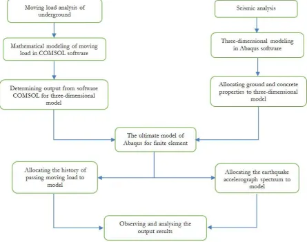
Because of the difference between the response of underground and surface structures, their design and analysis methods are also be different. In traditional methods, quasi-static analysis or equivalent static are used, while the analysis and design of underground structures are conducted based on deformation of structure and ground. Because the response of ground and tunnel structure against deformation induced by the earthquake is very sensitive. For the analysis of axial and bending deformations, using three-dimensional models are more suitable. In the lumped mass method, the tunnel is divided into a number of segments which are connected by springs representing the axial, shear, and bending stiffness of the tunnel. Soil reactions are simulated with vertical springs [18] and the analysis is conducted in the form of equivalent static. At the beginning, the time history of free field deformations is calculated at the selected point along the tunnel. Then, soil-structure interaction is considered at springs. Gomes et al [13] conducted a comprehensive study in the field of comparing the finite element analysis details with simple models for seismic analysis of tunnels and found that except for a few exceptions, simplified procedures will lead to conservative results. One reason for this is that, the effects of soil-structure interaction cannot be determined with the simplified procedures. The simulation process used in this study can be generalized to the ground mass, tunnel diameter, tunnel burial depth and orientation of locating tunnels with any arbitrary dimensions. In addition, the simulation algorithm of tunnels in this study can be generalized to any number of stories of tunnels with any type of the surrounding ground material of tunnels as well (see Fig. 1).
[image:3.595.75.521.372.723.2]2.
Modeling
2.1. The Parameters of Materials
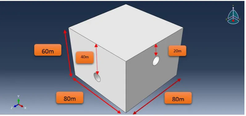
In this study, the accelerograph spectrum of Tabas earthquake was used for seismic analysis. It is worth noting that the type of dynamic analysis is of nonlinear dynamic. Also, the existing material properties are defined in accordance with Tables 1 and 2. It is worth mentioning that C3D8R element was used for meshing of the surrounding ground of tunnels and S4R element was utilized for meshing of tunnels. For conducting dynamic analysis, first a geostatistical analysis aiming at calculating in-situ stresses of soil was conducted (assuming that the soil or the ground has already been subsided). Also, we assumed that the location of the ground of tunnels was still full of soil and at this stage the location of the soil of tunnels was removed (tunnel excavation), shown in Fig. 2. Then, in the form of a static analysis, concrete lining was placed instead of removed soil of tunnels (tunnel excavation). And afterwards, double-deck tunnel model with the soil or its surrounding ground make a decision to dynamic analysis for seismic analysis. At this stage, the contact method was used for defining the interaction conditions at the time of excavating soil and then locating concrete lining in the tunnel and also contact between the tunnel concrete and its surrounding soil. A simulated image of two non-coplanar tunnels is shown in Fig. 3.
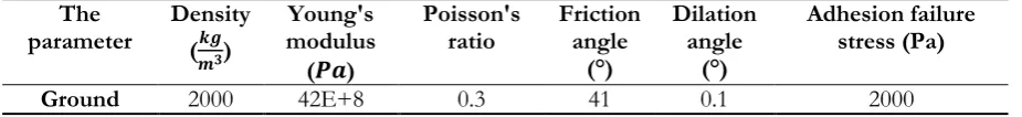
Table. 1. Input parameters of soil in numerical modeling.
Adhesion failure stress (Pa) Dilation angle (°) Friction angle (°) Poisson's ratio Young's modulus ( ) Density ( ) The parameter 2000 0.1 41 0.3 42E+8 2000 Ground
Table. 2. Input parameters of concrete in numerical modeling.
Concrete damage plasticity Plasticity
Viscosity parameter K
fb0/fc0 Eccentricity
Dilation angle (°)
0 0 0 0 36.31 Compressive Behavior
Inelastic strain (m/m) Yield stress (Pa)
0 13E+6
0.001 241E+5
2.2. The Characteristics of Dynamic Load
[image:4.595.76.539.329.382.2]Fig. 2. Simulated model of tunnel structure.
Fig. 3. The behavior of two non-coplanar tunnels.
[image:5.595.99.498.78.266.2] [image:5.595.97.500.300.489.2] [image:5.595.82.513.526.731.2]Fig. 5. Location of support no.4.
3.
Analysis of Output Results
3.1. Vibration of Ground Surface Due to Underground Passing
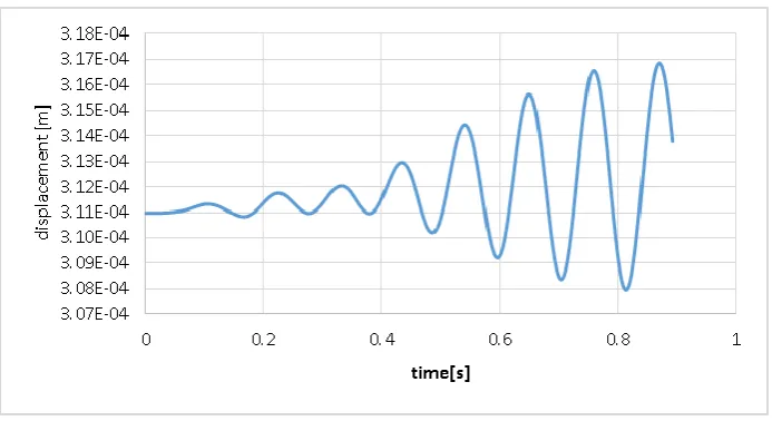
When the underground passes at high speed in the tunnel, if the surrounding soil of the tunnels is loose or the distance of tunnel to the ground surface is low, the intensity of these vibrations will be high and may result in the destruction of the foundation and structure subsidence of the ground surface as well. In Fig. 6, the vertical displacement of the ground surface at the top point of tunnels due to underground passing is shown. As shown in Fig. 6, the maximum displacement of ground surface due to underground passing that residents feel was equal to 0.31 mm.
Fig. 6. Displacement (vibration) of ground surface induced by underground passing with critical speed 89.699 m/s.
3.2. The Allowable Shear Stress of Soil on the Floor of Upper Tunnel
The floor of upper tunnel was at a depth of 25 meters from ground surface and thus the allowable shear strength of the soil at this depth with respect to the Mohr – Coulomb’s equation is obtained as Eq. (1).
[image:6.595.98.497.76.262.2] [image:6.595.125.472.431.620.2]where is shear strength (pa); is vertical stress on the failure plane (pa); is friction angle between grains of soil (degree); and c is soil cohesion (pa).
Accordingly, the allowable shear stress of soil is calculated using Eq. (2).
(2)
In the above equation, is the depth of desired point from the ground surface (25 m); is the height of concrete column above the desired point (m); is the normal stress induced by the weight of soil to the desired depth and the weight of the concrete column of the tunnel liner above the desired point (pa); and SF (safety factor) with high significance is considered 2 in the seismic loading of structures (U.S. Army Corps of Engineers). According to Eq. (1) and (2), the allowable shear stress of soil on the floor of upper tunnel was calculated which its value was equal to 0.237 MPa in this model.
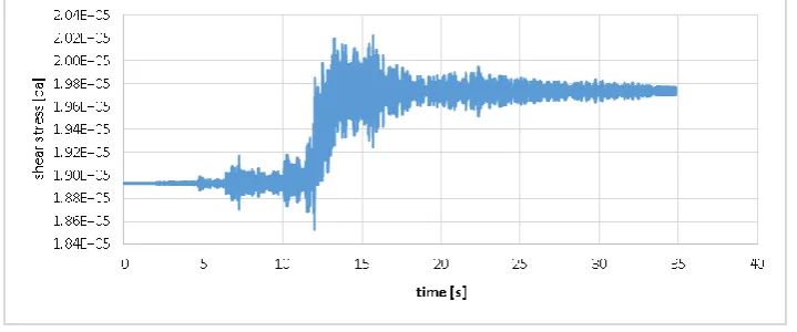
As shown in Fig. 7, the maximum shear stress on the floor of upper tunnel was occurred at 15.72 (sec) which its value was equal to 0.202 MPa that was approximately close to the calculated allowable shear stress of soil in this depth (upper tunnel floor 25 meters) which was equal to 0.237 MPa. Thus, on the floor of upper tunnel in the direction of X, soil was on the verge of shear failure.
According to Fig. 8, the maximum shear stress on the floor of upper tunnel was occurred at 13.14 (sec), which its value was equal to 0.185 MPa that was far from the allowable shear stress of the soil at this depth which was equal to 0.237 MPa. Thus, it was not collapsed on the floor of upper tunnel in the direction of Y.
According to Fig. 9, the maximum shear stress on the floor of lower tunnel was occurred at 12.02 (sec), which its value was equal to 0.291 MPa. The calculated allowable shear stress of soil in this depth (upper tunnel floor at 25 meters depth from the ground surface) was equal to 0.422 MPa. Thus, the maximum shear stress was far from the calculated allowable shear stress in this depth. Therefore, the soil was not collapsed on the floor of lower tunnel in the direction of X.
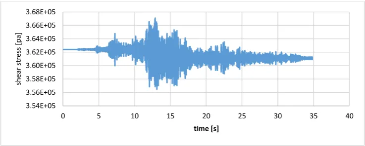
According to Fig. 10, the calculated maximum allowable shear stress of the soil was occurred at 12.88 (sec), the value of which was equal to 0.367 MPa that was approximately close to the allowable shear stress of the soil at this depth which was equal to 0.422 MPa. Thus, the soil on the floor of upper tunnel in the direction of Y was on the verge of shear failure.
[image:7.595.119.479.447.597.2]Fig. 8. Shear stress in the direction of Y on the floor of upper tunnel.
Fig. 9. Shear stress in the direction of X on the floor of the lower tunnel.
Fig. 10. Shear stress in the direction of Y in the lower tunnel floors.
3.3. Evaluation of the Shear Failure in Soil between Two Tunnels Due to Subway Passing
When the underground passes at high speed on rail, it causes generating support forces that these support forces are eventually transferred to soil under the rails and incurred by soil. The amount of the shear stress induced by the underground passing can be observed and compared with the amount of allowable shear stress of soil.
According to Fig. 11, the shear stress induced by the underground passing in the tunnel at a critical speed was equal to 0.19 MPa. Resistant shear stress in the depth of the soil on the floor of upper tunnel
1.68E+05 1.70E+05 1.72E+05 1.74E+05 1.76E+05 1.78E+05 1.80E+05 1.82E+05 1.84E+05 1.86E+05 1.88E+05 1.90E+05
0 5 10 15 20 25 30 35 40
sh ear st re ss [ pa ] time [s] 2.76E+05 2.78E+05 2.80E+05 2.82E+05 2.84E+05 2.86E+05 2.88E+05 2.90E+05 2.92E+05 2.94E+05
0 5 10 15 20 25 30 35 40
sh ear st re ss [ pa ] time [s] 3.54E+05 3.56E+05 3.58E+05 3.60E+05 3.62E+05 3.64E+05 3.66E+05 3.68E+05
0 5 10 15 20 25 30 35 40
[image:8.595.122.476.76.247.2] [image:8.595.119.477.282.434.2] [image:8.595.113.482.469.617.2]was equal to 0.236 MPa that this value was approximately close to the allowable shear stress and soil is on the verge of collapse.
Fig. 11. Shear stress induced by the underground passing at the critical speed on the floor of the upper tunnel.
3.4. Examining the Displacement of Upper Tunnel Relative to Lower Tunnel
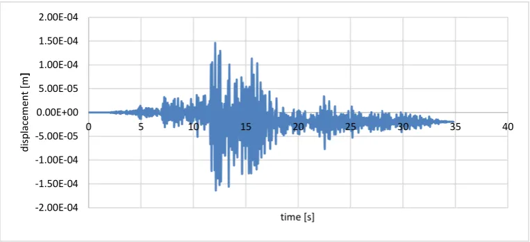
Another thing that is important in the design of the tunnels with two or more stories is the displacement of tunnels of floors relative to each other and if these displacements are relatively much, cause inducing extra stress in soil and disturbing the tunnel route geometry. In Figs. 12 and 13 the displacement of the floors of two upper and lower tunnels relative to each other due to earthquake is shown in two orthogonal directions. According to Figs. 12 and 13, the relative displacement of tunnels to each other was less than 10 mm [19, 20]. Thus, it did not cause problem in structures tunnel.
Fig. 12. The displacement in the direction of X for the upper tunnel relative to lower tunnel.
1.89E+05 1.89E+05 1.89E+05 1.89E+05 1.89E+05 1.90E+05 1.90E+05 1.90E+05 1.90E+05 1.90E+05 1.91E+05
0 0.1 0.2 0.3 0.4 0.5 0.6 0.7 0.8 0.9 1
sh
ear
st
re
ss
[
P
a]
time [s]
-2.00E-04 -1.50E-04 -1.00E-04 -5.00E-05 0.00E+00 5.00E-05 1.00E-04 1.50E-04 2.00E-04
0 5 10 15 20 25 30 35 40
di
sp
lac
em
ent
[
m
]
[image:9.595.107.489.441.615.2]
Fig. 13. The displacement in the direction of Y for the upper tunnel relative to lower tunnel.
3.5. Examining the Stress Induced by the Earthquake in the Concrete Liner of Tunnel
When any structure is exposed to the earthquake, in addition to the stresses induced by static loads such as weight, stresses induced by dynamic loading are formed as well, that in this section, these stresses in the concrete of tunnel liner are discussed.
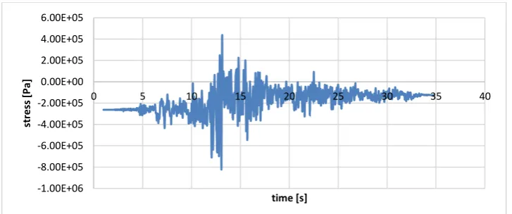
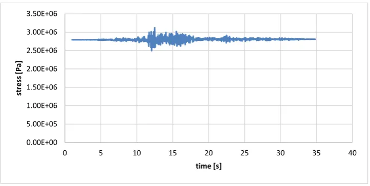
[image:10.595.103.485.379.748.2]Components of the stress in the concrete of the liner at the upper and lower tunnels are displayed in Figs. 14 to 17. The stress produced in the concrete liner due to dynamic loading was less than the allowed limit of compressive and tensile stress in the concrete that was equal to 30 and 5 MPa, respectively. Thus, the seismic loading did not cause failure and damage in concrete liner.
Fig. 14. The generated stress in the direction of X in the concrete of upper tunnel liner.
Fig. 15. The generated stress in the direction of Y in the concrete of upper tunnel liner.
-2.00E-04 -1.50E-04 -1.00E-04 -5.00E-05 0.00E+00 5.00E-05 1.00E-04 1.50E-04 2.00E-04
0 5 10 15 20 25 30 35 40
di spl acem e nt [ m ] time [s] 0.00E+00 2.00E+05 4.00E+05 6.00E+05 8.00E+05 1.00E+06 1.20E+06 1.40E+06 1.60E+06 1.80E+06
0 5 10 15 20 25 30 35 40
st re ss [ P a] time [s] -1.00E+06 -8.00E+05 -6.00E+05 -4.00E+05 -2.00E+05 0.00E+00 2.00E+05 4.00E+05 6.00E+05
0 5 10 15 20 25 30 35 40
[image:10.595.117.481.590.742.2]Fig. 16. The generated stress in the direction of X in the concrete of lower tunnel liner.
Fig .17. The generated stress in the direction of Y in the concrete of lower tunnel liner.
3.6. Examining the Ovaling of the Circular Tunnel Section Caused by the Earthquake
Due to in-situ static loading of the soil and in fact due to the weight of the soil above the crown and then in seismic loading, the circular tunnel sections are suffered by ovaling that if this amount of ovaling is larger than 10 mm, tunnel design and especially thickness of concrete liner must be revised [19, 20]. In Fig. 18, the value of ovaling of the lower tunnel due to the high height of the soil above the head of it is illustrated. The ovaling value of lower circular tunnel due to being critical was equal to 0.8 mm.
0.00E+00 2.00E+05 4.00E+05 6.00E+05 8.00E+05 1.00E+06 1.20E+06
0 5 10 15 20 25 30 35 40
st
re
ss
[
P
a]
time [s]
0.00E+00 5.00E+05 1.00E+06 1.50E+06 2.00E+06 2.50E+06 3.00E+06 3.50E+06
0 5 10 15 20 25 30 35 40
st
re
ss
[
P
a]
[image:11.595.117.479.285.467.2]Fig. 18. Ovaling of the lower tunnel section due to the pressure of the soil column in seismic loading.
4.
Conclusion
The evaluating of seismic performance of structures associated with transportation system is very important. Hence, in this paper, the seismic behavior of underground tunnel under the non-linear behavior has been investigated. In order to determine the severity of possible damages, the base of judgment was placed on the occurred deformations in the body of the tunnel. Based on the analysis performed following results were obtained.
1) The soil between the upper and lower tunnel was on the verge of shear failure and this area was even more critical relative to the soil under the lower tunnel which was under more weight. The most important reason for this was that there was no bed under the soil mass between two non-coplanar tunnels as lower tunnel. In addition, the space under upper tunnel due to existing of lower tunnel was empty. Thus, there was no homogeneous environment.
2) The stress generated in the concrete liner was low so that the concrete does not entered to the failure area.
3) The displacement of two tunnels relative to each other was low; therefore, it does not create a particular problem in the structure.
Although the results obtained from this study indicate a general stability of the studied tunnels at the time of shaking occurrence meanwhile, conducting further research for underground structures with more geometric diversity and also in different tectonic and geotechnical conditions is necessary to achieve generalizable results.
References
[1] T. R. Keusel, “Earthquake design criteria for subways,” Journal of Structural Division, vol. 95, no. 6, pp.1213-1231, 1969.
[2] W. S. Douglas and R. Warshaw, “Design of seismic joint for San Francisco Bay Tunnel,” Journal of Structural Division, vol. 97, no. 4, pp. 1129-1141, 1971.
[3] C. Dowding and A. Rozen, “Damage to rock tunnels from earthquake shaking,” Journal of Geotechnical Engineering, vol. 104, no. 2, pp. 175-191, 1978.
[4] G. N. Owen and R. E. Scholl, “Earthquake engineering of large underground structures,” Report No. FHWA/RD-80/195, Federal Highway Administration and National Science Foundation, 1981. [5] C. M. St. John and T. F. Zahrah, “A seismic design of underground structures,” Tunnelling and
Underground Space Technology, vol. 2, no. 2, 1987.
[6] S .Sharma and W. R. Judd, “Underground opening damage from earthquakes,” Engineering Geology, vol. 30, pp. 263–276, 1991.
0.8 mm
[7] T. R. Kuesel, E. H. King, and J. O. Bickel, Tunnel Engineering Handbook, 2nd ed. Springer, 1996.
[8] K, Kawashima, “Seismic design of underground structures in soft ground: A review,” in Geotechnical Aspects of Underground Construction in Soft Ground, O. Kusakabe, K. Fujita, and Y. Miyazaki, Eds. Rotterdam: Balkema, 2000.
[9] C. H .Chen, T. T .Wang, F. S. Jeng, and T. H. Huang, “Mechanisms causing seismic damage of tunnels at different depths,” Tunnelling and Underground Space Technology, vol. 28, pp. 31–40, 2012. [10] Z. Z. Wang and Z. Zhang, “Seismic damage classification and risk assessment of mountain tunnels
with a validation for the 2008 Wenchuan earthquake,” Soil Dynamics and Earthquake Engineering, vol. 45, pp. 45–55, 2013.
[11] Y. Shen, B. Gao, X. Yang, and S .Tao, “Seismic damage mechanism and dynamic deformation characteristic analysis of mountain tunnel after Wenchuan earthquake,” Engineering Geology, vol. 180, pp. 85–98, 2014.
[12] M. A. Abdel-Motaal, F. M. El-Nahhas, and A. T. Khiry, “Mutual seismic interaction between tunnels and the surrounding granular soil,” HBRC Journal, vol. 10, no. 3, pp. 265–278, 2014.
[13] R. C. Gomes, F. Gouveia, D. Torcato, and J .Santos, “Seismic response of shallow circular tunnels in two-layered ground,” Soil Dynamics and Earthquake Engineering, vol. 75, pp. 37–43, 2015.
[14] K. Pitilakis, G. Tsinidis, A. Leanza, and M. Maugeri, “Seismic behaviour of circular tunnels accounting for above ground structures interaction effects,” Soil Dynamics and Earthquake Engineering, vol. 67, pp. 1–15, 2014.
[15] Z. Y. Chen and H. Shen, “Dynamic centrifuge tests on isolation mechanism of tunnels subjected to seismic shaking,” Tunnelling and Underground Space Technology, vol. 42, pp. 67–77, 2014.
[16] Z. Z. Wangn and Z. Zhang, “Seismic damage classification and risk assessment of mountain tunnels with a validation for the 2008 Wenchuan earthquake,” Soil Dynamics and Earthquake Engineering, vol. 45, pp. 45–55, 2013.
[17] G. N. Owen and R. E. Scholl, “Earthquake engineering of large underground structures,” Report No. FHWA/RD-80/195, Federal Highway Administration and National Science Foundation, 1981. [18] B. Schmidt and Y.M.A, Hashash. “Seismic rehabilitation of two immersed tube tunnels,” World
Tunnel Congress, Sao Paulo, Brazil, April 25-30, 1998.
[19] M. Esmaeili and F. Bashiri Rad, “Seismic analysis and design of underground structures,” Sharif University of Technology publications, 2014.