Shear Bloch waves and coupled phonon-polariton in periodic piezoelectric waveguides
D.G. Piliposyan1, K.B Ghazaryan2, G.T. Piliposian31
1,2Department of Dynamics of Deformable Systems and Coupled Fields, Institute of Mechanics, Bagramyan ave 24B, Yerevan, Armenia, 0019
3Department of Mathematical Sciences, The University of Liverpool, M&O Building, L69 7ZL, Liverpool, gayane@liv.ac.uk
Abstract
Coupled electro-elastic SH waves propagating in a periodic piezoelectric finite-width waveguide are considered in the framework of the full system of Maxwell’s electrodynamic equations. We investigate Bloch-Floquet waves under homogeneous or alternating boundary conditions for the elastic and electromagnetic fields along the guide walls. Zero frequency stop bands, trapped modes as well as some anomalous features due to piezoelectricity are identified. For mixed boundary conditions, by modulating the ratio of the length of the unit cell to the width of the waveguide, the minimum widths of the stop bands can be moved to the middle of the Brillouin zone. The dispersion equation has been investigated also for phonon-polariton band gaps. It is shown that for waveguides at acoustic frequencies, acousto-optic coupling gives rise to polariton behaviour at wavelengths much larger than the length of the unit cell but at optical frequencies polariton resonance occurs at wavelengths comparable with the period of the waveguide.
Keywords: Piezoelectric phononic crystal, bang gaps, Floquet theory, phonon-polariton.
1. Introduction
The interaction of waves with periodic structures, especially artificial superlattices, has recently attracted much attention. A periodic modulation of the dielectric or elastic material properties leads to absolute stop bands and ultimate control of the propagation of waves in the structure. The interaction of light with periodic dielectric materials results in a photonic crystal which exhibits a frequency range for which the structure forbids the propagation of electromagnetic waves [Yablonovitch, 1987]. Photonic crystals have opened new features for controlling light, leading to the potential applications in many novel devices [Fan et al., 1998].
In the phononic crystal counterpart a periodic modulation of elastic coefficients can create a phononic band gap for which the propagation of elastic waves is forbidden [Sigalas and Economou, 1992]. These materials have found several applications including in the field of wave guiding and filtering [Achaoui et al, 2010] and sound isolation [Liu et al, 2000].
The existence of architectures simultaneously exhibiting both complete photonic and phononic band gaps has also been discussed [Maldovan and Thomas, 2006] opening the possibility of dual acousto-optic devices.
Coupling of acousto-optic interaction can be expected also in piezoelectric superlattices where piezoelectric or piezomagnetic composites are periodically made up of two or more different constituents. Compared with purely elastic crystals they exhibit electric or magnetic effects with novel acoustic properties. Currently thin film piezoelectric layered structures are widely used to satisfy the increasing demand for higher frequency, higher performance, smaller size, lower cost and lower energy consumption technologies. The investigation of acoustic waves in piezoelectric phononic crystals has recently attracted much attention and problems concerning the propagation of acoustic waves both in two and three dimensional piezoelectric periodic structures are considered in Vashishth and Gupta (2009), Wang et al. (2009), Wilm et al. (2002).
The purpose of this paper is to investigate the propagation of SH Bloch waves in a piezoelectric periodic waveguide. Unlike many previous studies we will solve the problem in a dynamic setting for Maxwell’s equation where both the optical effect and the effect from the rotational part of the electric field are taken into account. This setting will provide more insight into wave propagation properties both at acoustic and optical frequencies [Piliposian et al., 2012; Belubekyan, 2008]. The dispersion equation will also describe the coupling of elastic and electromagnetic properties called a phonon polariton, which is the counterpart of the coupling of phonons and photons in ionic crystals originating from a coupling between lattice vibrations (transverse optical phonons) and electromagnetic waves (photons) in the infrared region. Due to piezoelectricity the same phenomenon takes place in a piezoelectric superlattice where the periodicity of the lattice is expanded from atomic scale to microns and the phonon polariton gap expanded from the infrared to microwave region [Zhang et al., 2004, Zhao et al, 2008, Senesi and Ruzzene, 2011, Xu et al, 2013]. This problem, which has not been considered for waveguides, can find new applications in acousto-optic devices.
wavefield modes of an infinite homogeneous waveguide [Pagneux and Maurel, 2006]. By using a modified expression of the orthogonality relation between normal modes of the piezoelectric waveguide, the fields are represented as the sum of the normal-mode waves propagating along both directions of the waveguide. This gives a method for determining all possible boundary conditions on the guide walls when the orthogonality property holds and also helps to construct transfer matrices across the internal material interfaces. The problem can also be solved for the case where the waveguide has periodically alternating boundary conditions along the guide walls.
2. Solutions in a homogeneous waveguide
First we consider the propagation of elasto-electromagnetic coupled SH waves in a one dimensional infinite piezoelectric waveguide of hexagonal symmetry class. The problem will be considered in the framework of the full dynamic system of Maxwell’s equations which will give an opportunity to study the wave dispersion equation both at acoustic and optical wave frequency regions. For an anti-plane problem the interconnected elastic and electro-magnetic excitations in a transversely isotropic piezoelectric crystal with crystallographic axes directed along the Oz direction are with respect to uz, Ex,Ey,Hz [Ghazaryan and Piliposyan, 2012]
2
2
yz
xz uz
x y t
,
z
xz 44 15 x
x
u
c e E
, yz 44 z 15 y,
u
c e E
y (1) , t H μ y E x E z 33 x y , y z D H x t
t ,
D y
Hz x
(2)
15 11 15 11
z z
x x y y
u u
D e ε E , D e ε E ,
x y
(3)
where uz is the displacement,
ik the stress tensor, Dk and Ek the electric displacement andelectric field intensity, Hz the magnetic field intensity, and ,c44,e15,
11,
33 the mass density, elastic, piezoelectric, dielectric and magnetic constants respectively. Harmonic time dependence in the form exp(it) for the all time-dependent variables (with as wave angular frequency) is assumed henceforth. Writing e15e, c44G,ε11ε, Hi H z,uz u, eliminating Dx and Dy, equations (1)-(3) can be rewritten in terms of the variables E x yy( , ),u x y( , ),H x y( , ), xz( , )x y all of which will be continuous across material interfaces when considering a periodic waveguide:2
2 2
0 0 0 0
xz xz
y
E u H
,
x y x y
G e e
H ,
G y G G G
2 2 2 y xz y E H u
E e , e G
y y y u,
x x
2
0
G G e /.
Following the formalism adopted in Pagneux and Maurel (2006) for the inplane problem, here we introduce the vectors
z
E x y u x yy( , ), ( , )
T, r
( , ), xz(x, y)
TH x y
(5)
and write the system of equations (4) in the matrix operator form ˆ 0 ˆ 0 z z r r F x Q
, (6)
where ˆF and ˆQ are the following operator matrices
2 0 0 2 0 0 ˆ , ) ˆ ( 1 yy y y y yy y G e e G G F Q e G e G G
. (7)
Boundary conditions on the waveguide walls will be imposed on the variables ,u H,σyz and
x
E x, y . The latter two can be expressed in terms of the variables E x y u x yy( , ), ( , ),H x y( , ) and (x, y)
xz
as follows:
0 0
xz
z y x
y e G u H E . G G
σ G eE ,
y y
(8)
This implies that any boundary conditions on the waveguide walls also can be expressed in terms of unknown vectors zandr.
The solution to (6) can be found by separating the variables in the form
i ( ) ( ) z z r r kx y e y ,
which leads to an eigenvalue problem with discrete eigenvalues kn and corresponding mode solutions (z rn, )n T, where
( ) (y), ( )
zn y un Eyn y T , rn( )
xz (y), n( )
Tn H
y y (9)
each satisfying the eigenvalue problem
ˆ 0 i ˆ 0 z z r r n n n n n F k Q
. (10 )
rn associated with different modes corresponding to eigenvalues km and kn satisfy the following equations: 2 ˆ
ˆ z z ,
m m m
FQ k ˆ ˆ 2
.
rn nrn
QF k (11)
We define the inner product of two vectors u( ,u u1 2) and v( ,v v1 2) as
1 1 2 2
0|
u v
h
u v u v dy
.Then the operators Fˆ and Qˆ have the following properties:
ˆ | | ˆ ( )
n m n m
F F h
r r = r r , Qˆzn|zm = zn|Qˆzm ( )h , (12) where
0
0
, y h
y h
n xm m xn yzn n yzn m
h H E H E h u u
. (13)
It follows from (12) that if ( )h 0 and ( )h 0 the operators Fˆand Qˆ are self adjoint and
FQˆ ˆzm|rn zm|QFˆ ˆrn. (14)
Using (11) and (14) we get the following orthogonality relation between modes for coupled waves at a constant frequency and differing wave numbers km and kn
0
| ,
z r
h
n m un y xzm y Eyn y Hm y dy Jnnm
(15)where mn is the Kronecker delta operator and the form of Jn depends on the boundary conditions
on the waveguide walls and is given below for different cases.
Equations (13) give possible boundary conditions ensuring the orthogonality of the eigenfunctions. In particular equations (10) have the following solutions (where dimensionless coordinates xxh, yyh have been introduced and the tilde sign is omitted henceforth):
sin
( , ) , cos n n n n p y u x y a
p y x
cos ( , ) , sin n n n n p y H x y ec xp y
(16)
0 sin ( , ) ( ) , cos nxz n n
n
p y x y G w x
p y
cos ( , ) ( ) , sin ny n n
n
p y
E x y v x
p y
(17)
where
1
( ) ,
n n n n
i n
w x q b x p c x v xn( )
1i pn na x
s dn n
x , i1, 2, (18)2 2 2
2 2
2 2 0
0 2 0 2 0 1 ,
, , n n n n, , ,
G
h h
p s p c c
c c
e e
q
G
(19)
0
c is the velocity of a transverse wave in the medium, cis speed of the electromagnetic wave,
1,2
exp exp , exp exp ,
exp exp , exp exp ,
n n n n n n
n n n n n n
n n n n
n n n n
a x A iq B iq b x i A iq B iq
c x C is D is d x i
x x x x
x x C is x D is x
(20)
where A Bn, n ,C Dn, n are constants. The parameters qn and sn stand for the eigenvalues kn determined from the characteristic equation of (10), and the dimensionless parameters pn
determined from boundary conditions on the waveguide walls. The term e in the expression for ( , )
n
H x y in (16) is included to harmonise the dimensions of all the wave-field functions.
The upper terms in (16) and (17) and case i1 in (18) correspond to displacement-clamped and electrically-shorted boundary conditions on the waveguide walls:
,0 0,
,0 0,
,1 0,
,1 0, .n xn n xn n
u x E x u x E x p n (21)
The lower terms and case i2 correspond to traction free and magnetically-closed boundaries:
,0 0,
,0 0,
,1 0,
,1 0, .n yzn n yzn n
H x x H x x p n (22)
The upper terms and case i1 also satisfy the following boundary conditions:
,0 0,
,0 0,
,1 0,
,1 0,
2 1
,2
n xn yzn n n
n
u x E x x H x p n0,1,2... (23)
Note that the electrically-shorted condition can for example be obtained by coating the wall with a thin metallic layer, and the magnetically-closed condition obtained by coating the corresponding layer with a superconducting thin layer.
For all the above cases the orthogonality condition (15) holds, moreover this condition is decoupled into two separate conditions:
1 1
0 0
1 1
, .
2 2
n xzm nm yn m nm
u y y dy E y H y dy
(25)For a piezoelectric waveguide there also exists boundary conditions for which the orthogonality condition (15) is satisfied but the elastic and electromagnetic functions are coupled on the waveguide walls, for example when the walls are electrically-shorted and mechanically traction free [Yang, 2004]. As another example of such a waveguide consider the following conditions on the waveguide walls:
un
x, 0 0, Exn
x, 0 0, Exn
x,1 0, yzn
x,1 0. (26) In this case the mode solutions of equations (6) can be derived as( ) , ( )
z r
n n n n a x b x
(27)
where
sin
,
n ncos
n n2 ncos
n
,n n yn
n
q s q y p s y
u y q y E y
s
cos
,
0
sin
s
sin( ) ,
i
n( ) n
si n n
n n n
n
xzn n
n
n n n
n q e
H y s y y p G s q
s y q y s
. (29)
Positive and negative eigenvalues pn for this problem are determined from the following dispersion equation:
2
cos sin sin cos 0.
n
n n n n
n n p
s q s q
q s
(30) In this case in the orthogonality relationship (15)
3
3
2 2
0 2 2 2
2 sin(2 ) cs )sin ( ) ( 2 )sin 2 2 .
4 n n n n n n n c ( n n n n n
n n n
n
p s q q p q s q p s s p s
s G J
q
(31)
Note that without the piezoelectric effect the dispersion equation (30) decouples into solutions defining the eigenvalues pn at acoustic frequencies
2 2 2 2 2
0 ,
n n
p h c q qn (2n1) / 2and optical
frequencies pn22h c2 2sn2, sn n. Equation (30) has also interesting solutions in the short wave (h) and long wave (h0) approximations. If for dimensional eigenvalues kn p hn
we write the dispersion equation (30) as
2
0 0
0 0
tanh tanh
n
n n
n n k
q h s h
q s
, (32)
with 2 2 2
0n n 0,
q k c 2 2 2
0n n ,
s k c then at frequencies kc0, when hthe dispersion relation (32) can be approximated by 2
0 1
n k c
. This equation defines the phase velocity
n
k
of an acoustic Bleustein–Gulyaev surface wave for a traction-free and electrically-shorted elastic half-space. For the long wave approximation the dispersion equation (32) gives
1
n
k c
. This relation characterizes high frequency electromagnetic waves in a very thin layer. Note that in this case there is a strong dependence of phase velocity on the electromagnetic coupling coefficient .
3. Modal Solutions
We consider an infinite one-dimensional periodic piezoelectric structure with unit cells of length
consisting of piezoelectric segments of length a1 attached and perfectly bonded to elastic segments made of another piezoelectric material of length a2 (= a1 + a2) as shown in Figure 1.
Fig.1. Periodic waveguide made from two piezoelectric media.
The solution of (16)-(17) within each material of the guide can be written in the form
(33)
where j1, 2,zn( )y and rn( )y are defined by (9), an, cn, vn, wn , have the same notations as in (18)-(20), and superscripts 1 and 2 indicate that the functions belong to media 1 and 2 .
The continuity conditions at the interfaces x=0 and x a1 can be written as
(1) ( 2)
(1) ( 2)
(1) ( 2)
(1) ( 2)
(1) ( 2)
(1) ( 2)
( ) ( ) ( ) ( ) ( ) ( ) ( ) ( ) ( ) ( ) ( ) ( ) z z r r n n n n n n n n n n n n n n
v x v x
y y
a x a x
c x c x
y y
w x w x
, (34)where (2) (1)
0 0 ,
G G
(2) (1)
,
(2) (1)
. e e
Taking the inner product (15) of the upper block of (34) by a single mode rn( )y and the lower block by zn( )y , and introducing vectors
( ) ( ) ( ) ( )
, , ,
aj b j c j dj
defined by ( ) ( )
1,2, ,
( )
a j j
n n N
a x
(the same for ( ) ( ) ( )
, ,
b j c j d j
), the interface conditions at x0 and x a1 can be written in a block matrix form
2 1
1 2
1 0 y x 2 h
-a1 a2
( ) (j)
(j) ( )
(j)
(j) ( ) (j)
(j) ( ) (j)
0 ( ) ( ) ( ) , ( ) ( ) ( ) z z r r j n n j n j n n n j n v x y a x
e c x
y G w x
ˆ1
a(1)( ),b(1)( ),c(1)( ),d(1)( )
ˆ2
a( 2)( ),b( 2)( ),c( 2)( ),d( 2)( )
T T
R x x x x R x x x x . (35)
In (35) Rˆ1 and Rˆ2 are the following block matrices:
(1) (1) ( 2) ( 2)
1 2
1 2
(1) (1) ( 2) ( 2)
ˆ 0 0 0 ˆ 0 0 0
ˆ ˆ ˆ ˆ ˆ ˆ
0 0 0 0
ˆ , ˆ
ˆ ˆ
0 0 0 0 0 0
ˆ ˆ
ˆ ˆ 0 0 ˆ ˆ 0 0
L I
LK LP K P
R R
M I
MP MQ P Q
, (36)
ˆ
L, Mˆ and the diagonal matrices ˆ( )j
K and ˆ( )j
Q have elements
1
(1) ( 2)
0
( ) ( ) , mn n xzm L
u y y dy1
(1) ( 2)
0
( ) ( ) , mn n y m
M
H y E y dy Kmn( )j qn( )jnm, ( )j ( )jmn n nm
Q s ,Pmn( )j ( 1)jpn(j)nm ,
) , 2 , 1 ,
(mn N ,(j1,2). The matrix ( )j
P depends on the boundary conditions on the waveguide walls. We also need the transfer matrix within a homogeneous material [Pagneux and Maurel, 2002] which for the piezoelectric material is
( ) ( ) ( ) ( ) ( ) ( ) ( ) ( ) ( ) 0 0 0 0 ( ') 0 0 0 0 n n n n n n n n j j q q j j q q j j j s s j j s s C S S C x C S S C
, (37)
where ( )
,
n j q
C ( )
,
n
j q
S ( ),
n j s
C ( )
n j s
S are matrices with entries cos(q( )nj ( 'xx)), ( )
sin( j ( ' )), n
q xx
( )
cos( j ( ' )) n
s xx and sin( ( )j ( ' )). n
s xx Writing the Bloch-Floquet conditions as
2 2 2 2
2
2
2
2
0 1 1 1 1 2 2 2 2
exp( ) a ,b ,c ,d a ,b ,c ,d ,
T T
ιk -a -a -a -a a a a a
where k0 is the Bloch wave number, and using the transfer matrices (36) across the interfaces and
(37) within a homogeneous material we arrive at the following eigenvalue problem
2 2 1 1 2 2 1 1( 2) 1 (1) 1
0 2 2 1 1 1 2
2 2 1 1 2 2 1 1 exp( ) a a b b c c d d a a a a
ιk T a R R T a R R
a a a a
. (38)
For homogeneous boundary conditions on the guide walls, Lˆ and Mˆ in (36) become identity matrices, the propagating modes separate from each other, and, writingexp(ιk0), each gives
rise to the following dispersion equation [Piliposian et al., 2012]:
4 3 2
( , , ) ( , ) ( , ) ( , ) 1 0,
,
2
1 2
, ,
2 2 1
1 2 2
1 1 2 2
,f p A P Q Q g p AP Q Q QR Q R (40)
(1)2 ( 2)2 ( 2)2 (1)2
(1) ( 2) (1) ( 2)
1 2 (1) ( 2) (1) ( 2) 1 2
cos cos sin sin
2
q q
P a q a q a q a q
q q
, (41)
(1)2 (1)2 (2)2 (2)2
(1) (2) (1) (2)
1 2 (1) (2) (1) (2) 1 2
( )
cos cos sin sin
2
G s G s
A a s a s a s a s
q q G G
, (42)
(1,2) (1,2)
(2,1)
2,1
(1,2) (2,1) (1,2) (1,2)
1,2 2,1 (2,1) (2,1) (1,2) 1,2 1,2
1, ,2
2 1
sin
cos cos cos cos ,
sin 1
a s
G r
a q a s a q a s
G a s
R
r
(43)
2
2 (1) (2) (2) (1) 2 (1,2)
1,2 (1,2) (2,1)
(2,1)
1,2 2,1
(1,2) (1,2) (2,1)
sin sin
,
p e a s a
Q q G s e q
(44)
and in (43) and (44) the first values in subscripts and superscripts correspond to R1 and Q1 and
the second values to R2 and Q2. The index n is omitted in parameters
( ) ( )
,
j j
n n
q s .
Taking into account that
12cos
k the solutions of the dispersion equation (39) are2
0
1
cos( ) ( 4 8) 0,
4
k f f g
(45)
and 2
0
1
cos( ) ( 4 8) 0
4
k f f g
. (46)
Dispersion equations (45) and (46) are the same both for displacement-clamped and electrically-shorted (21), and traction free and magnetically-closed (22) boundary conditions on the waveguide walls. In the case of boundary condition (21) mode n0 leads to a solution for the electromagnetic field independent of y, H x y( , )H x( ), and a trivial solution for the displacement, giving the propagation of a pure electromagnetic wave described by the dispersion equation cos(k0)P. In the case of boundary condition (22) mode n0 leads to a solution for the displacement that is independent of y, u x y( , )u x( ), and a trivial solution for the electromagnetic field function, giving the propagation only of an acoustic wave described by the dispersion equation cos(k0)A with the piezoelectric effect present only in the piezoelectrically stiffened elastic modulus G0 .
Equations (45) and (46) give the complete dispersion relation for the periodic piezoelectric waveguide and include information about a coupled elasto-electromagnetic SH wave and phonon-polariton.
For a superlattice with cells composed of two identical but oppositely polarized piezoelectric materials (e1e,e2 e)of equal widths a2 a1 a, equations (45) and (46) take the following simple form:
2 0
2
2 2
2 2
1
cos( ) cos 2 cos 2 2 sin sin 2
cos cos 4 cos cos sin sin
p
ak aq as aq as
qr
p
aq as aq as aq as
qr
. (47)
It is clear from (47) that band gaps are possible in this case.
For homogeneous boundary conditions (21), (22), (23), mode separation physically means no-mode conversion at the interface. This is due to the fact that the modes with respect to y are independent of material parameters, making separation of variables and consideration of the problem mode by mode possible. In the case of boundary conditions (26) the elastic and magnetic variables are coupled on the waveguide walls, further, the modes with respect to y are dependent on the material parameters. In this case although the orthogonality relationship within each constituent material is preserved, no-mode conversion property at the interface no longer holds. In this case one can expect similar effects to the elastic in-plane problem [Adams et al, 2009], where the equations of elasticity can be decomposed into two uncoupled scalar Helmholtz equations in two potentials coupled via the boundary conditions. Here, for the anti-plane piezoelectric problem equations (1)-(3) are written via two uncoupled Helmholtz equations with respect to both the magnetic field and the anti-plane displacement, which are coupled on the boundaries. Mode mixing across the interface also occurs when the boundary conditions on the waveguide walls are independent of the material parameters but the waveguide has periodically alternating boundaries.
4. Numerical Results
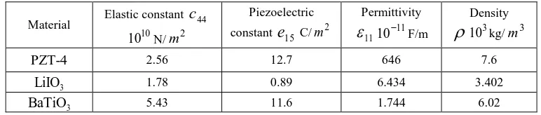
The structure of wave propagation depends on the ratio of the length of the unit cell to the height of the waveguide h, the reduced wave number k0, the filling fraction, and differences
[image:11.595.104.490.668.750.2]between the elastic and electromagnetic properties of two piezoelectric materials (Table 1) . Table 1.Material constants of PZT-4,LiIO3 andBaTiO3
Material Elastic constant
10
10 N/m2
Piezoelectric constant C/m2
Permittivity
11
11
10 F/m
Density
310 kg/m3
PZT-4 2.56 12.7 646 7.6
3
LiIO 1.78 0.89 6.434 3.402
3
BaTiO 5.43 11.6 1.744 6.02
44
c
15
For the displacement-clamped and electrically-shorted case (21) there exist cut off frequencies in the acoustic region for each material below which waves do not propagate. Below the lowest of these two frequencies no propagation will be possible creating a stop band. In the traction free and magnetically-closed case (22) propagating solutions exist around 0. In this case the lowest mode gives solutions only at acoustic frequencies where the piezoelectricity has a strong effect on the band structure (Figure 2a). Here for the normalized frequency c01, c01 is
the velocity of a transverse wave in material 1. For boundary conditions (21) the lowest mode gives solutions only at optical frequencies where the dispersion curves are not affected by the piezoelectric effect [Piliposian et al., 2012) (Figure 2b). Here, for the normalized frequency
1
c
, c1 is the speed of light in material 1.
(a) (b)
Fig.2. Band structure for a PZT-4 and LiIO3 piezoelectric phononic crystal for n0 a) acoustic frequencies for
traction-free and magnetically-closed boundaries, b) optical frequencies for displacement-clamped and electrically-shorted boundaries. Solid and dashed lines correspond to band structure with and without the piezoelectric effect.
The lowest mode for boundary conditions (21), which is the same as the first mode for boundary conditions (22), when the two materials in the waveguide have different cut-off frequencies, wave trapping occurs when the waves exponentially decay in one material. Figure 3 shows wave trapping for the lowest mode for a PZT-4 and LiIO3 waveguide, where the horizontal lines show the cut-off frequencies in the two materials. The nature of the trapping is not different from a non-piezoelectric waveguide described in detail in Adams et al. (2008) and is affected by both the difference in acoustic impedances and the wavelength in the sense of Postnova and Craster (2007). For a waveguide with long thin cells ( h) the mode is localized near the interfaces between the two materials for all values of reduced wave number in both piezoelectric and non-piezoelectric cases (Fig.3a), although it is nearly completely flat without the piezoelectric effect, and has a negative group velocity k0 with the piezoelectric effect. As the
for the piezoelectric waveguide vary more rapidly, with virtually no wave trapping region, only a zero cut-off at much lower frequency.
(a) (b)
Fig.3. Band structure for a PZT-4 and LilO piezoelectric phononic crystal for displacement-clamped 3 electrically-shorted boundaries for n1, (a) /h2, (b) /h0.2.Solid lines and dashed lines show the band structure with and without piezoelectric effect. Horizontal lines show the cut-off frequencies in the two materials.
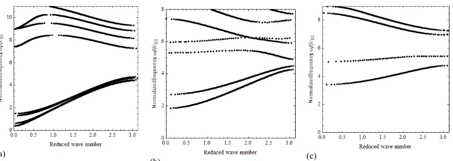
For a BaTiO3 and PZT-4 piezoelectric waveguide where there is a larger difference between the acoustic impedances, the frequency region with trapped waves is much larger and for shorter cells includes several modes (Fig. 4a). Although at acoustic frequencies the propagating modes are mainly determined by equation (46) and at optical frequencies by equation (45), for piezoelectric constituents with strong piezoelectric coupling, equation (45) contributes to the dispersion curves at relatively high acoustic frequencies (thick solid lines in Figure 4b). The band structure here does show an anomalous feature for very small values of the wave number
0
(a) (b) (c)
Fig.4. Band structure for a PZT-4 and BaTiO3 piezoelectric phononic crystal with displacement-clamped and electrically-shorted
boundaries for n1, (a) h2,(b) /h0.2,(c)/h0.5. Solid lines and dashed lines show the band structure with and without the piezoelectric effect, horizontal lines show the cut-off frequencies in the two materials. The thick bold lines show the contribution of equation (45).
A superlattice made up of oppositely polarized PZT-4 materials demonstrates interesting features. Figure 5a shows that for thinner cells the first band gap always occurs around the
0 0
k axis and the lower dispersion curve has two parts, the first part (thick line) described by equation (45) and the second by (46), the two meeting at a common maximum point when the group velocity is zero. The anomalous feature represented by (45) reduces as the unit cell lengthens (Fig. 5b), and disappears altogether for even larger values of h(Fig. 5c). The band gap however always occurs around the same resonance frequency and is not affected by this ratio.
(a) (b) (c)
Fig.5.a) Oppositely polarized PZT-4 crystals, a) h0.1,b) h0.3,c)/h1. Dashed lines show the band structure without piezoelectric effect, horizontal lines show the cut-off frequencies. The thick bold lines show the contribution of equation (45).
Another interesting feature here is that waves propagate below the cut off frequency (Fig.5b, 5c), which does not happen when the piezoelectric effect is neglected. This can also be shown analytically from the dispersion equation (47) where below cut off acoustic frequencies
2 2 2
0 0
c p
2
0
0
00 0 0 0
sinh sinh 2 cosh 2 2
cosh cosh
aq as
p
F as
q s aq as
, (48)
where sis0,qiq0ands0 0,q00. It follows that F
0 cosh
/h
cosh
/h
1
1 that means there is not a propagating mode. At the cut off frequency 0c p h0 , taking into account that
c0/c
2 1, F
0 can be approximated as 1 2 tanh
/ 4h
1, which meansthat there exists a region below the cut off frequency in which the wave propagation is possible.
4.1Periodic mixed boundary conditions
The transfer matrix (38) can also be used to solve the problem for piezoelectric waveguides with straight parallel boundaries with mixed boundary conditions. If the lower wall is displacement-clamped and electrically-shorted and the upper wall traction-free and magnetically- closed (23) the modes again separate and the problem is described by the dispersion equations (45) and (46) for all modes including mode n0. The band structure for the lowest mode in this case is similar to the band structure of the solutions for mode n1 with boundary conditions (21) and (22) (Fig.4). For a non-piezoelectric waveguide it shows a zero frequency stop band but no other gaps at higher frequencies. For piezoelectric waveguides there are significant band gaps and wave trapping, and similar anomalous features at higher acoustic frequencies (Fig. 4b).
nearly flat with no propagating energy (Fig.7c) and this is associated with mode trapping. Note that, as shown in Figure 6c, for a non-piezoelectric waveguide the same mixed boundary conditions are less conducive for trapping.
[image:16.595.65.532.138.287.2](a) (b) (c)
Fig.6. Band structure for a PZT-4 and BaTiO3 phononic crystal without piezoelectric effect in the case u0, Ex0 on the lower
wall and yz0, H0 on the upper wall in the first material, and vice versa in the second material, a) h0.1, (b)
0.5
h
, (c) h1.
(a)
[image:16.595.67.516.344.504.2](b) (c)
Fig.7. Band structure for a PZT-4 and BaTiO3 piezoelectric phononic crystal with piezoelectric effect in the case u0, Ex0 on
the lower wall and yz0, H0 on the upper wall,and vice versa in the second material, a) /h0.1, (b) /h0.5, (c)
/h 1.
(a) (b) (c)
Fig.8. Band structure for oppositely polarized PZT-4 phononic crystals with u0, Ex0 on the lower wall and yz0, H0
on the upper wall of the first material and vice versa in the second material, a) /h0.1 (b) /h1.3,(c) without piezoelectric effect /h1.3.
For an oppositely polarized piezoelectric waveguide with boundary conditions u0, Ex0 on the lower and upper walls in the first material and yz 0, H0 on the lower and upper walls in the second material, here again the ratio h can be modulated to get a very well defined minimum width for the band gap within the Brillouin zone (Fig.9b), which is clearly wider than the same feature for the homogeneous piezoelectric waveguide (Fig. 9a). For longer cell lengths the lowest dispersion curve becomes flat and is associated with trapped modes in the layer with displacement-clamped and electrically-shorted upper and lower boundaries (Fig 9c).
(a) (b) (c)
Fig.9. u0, Ex0 on the lower and upper walls in the first material, yz0, H0 on the lower and upper walls in the
5. Phonon-polariton modes
The analysis of equations (45) and (46) shows that at acoustic frequencies ( 1 0
c
) and as k0 0 there is an interaction between the quasi-electromagnetic wave described by equation
(45) and the quasi-acoustic wave described by equation (46). When the frequencies of these waves and wave numbers nearly coincide this interaction results in coupling and creation of two dispersion curves, low and high polaritons, separated by polariton band gaps [Maugin,1988]. Here again the size of the band gaps depend on material constants and the configuration of the piezoelectric superlattice. For example the band gaps are wider for larger values of the piezoelectric coefficients [Zhu et al, 2003, Zhang et al., 2004]. In the piezoelectric periodic waveguide the widths of polariton gaps depend also on the ratio h. Since the dispersion curve
of photons at acoustic frequencies is too close to the vertical axis (Fig. 10a, 10b) the coupling between the EM wave and superlattice vibration takes place in the long wavelength region (Fig. 10c). Figures 10c and 11a show the dispersion curves for a PZT-4 superlattice for h104and
3
10
h
. The oblique dotted line is the graph of cos(k0)P and represents the phase velocity of the pure electromagnetic wave. It is clear that for longer cell lengths the lowest order polariton band gaps appear at higher resonance frequencies and have narrower gaps (3.6% and 1.6% respectively). For a piezoelectric waveguide with constituents PZT-4 and BaTiO3 the lowest band
gap for 3
10
h
(Fig. 11b) appears at a much lower resonance frequency than for a PZT-4 superlattice. For h104 (Fig. 10c) it is at nearly the same frequency as for the PZT-4 superlattice but with a significantly narrower polariton gap of only 0.2%. Higher-order polaritons occur at higher frequencies but they have much narrower gaps (0.15%, 0.1%, Fig. 11b).
(a) (b) (c)
(a) (b) Fig.11 Polariton dispersion at acoustic frequencies for 3
10 ,
h
a) oppositely polarized superlattice PZT-4, b) PZT-4 and BaTiO3. Dotted oblique lines are the plots of equation cos(k0)P.
Dispersion equations contain information on phonon-polaritons at optical frequencies as well, as shown in Figure 12 where for the normalized frequency /c1, c1 is the speed of the electromagnetic wave. Drawn at optical frequencies, equations (45) and (46) fill the whole space with the interface line described by the equation cos(k0)P. The enlarged Figure 12b around one particular point on the interface line for a superlattice PZT-4 clearly shows the polariton gaps at optical frequencies. In this region the period of the lattice is comparable with the height of the waveguide( h0.4). The resonance occurs for short waves, unlike phonon polaritons at acoustic frequencies. For a piezoelectric waveguide with constituents PZT-4 and BaTiO3 the dispersion curves again show clear polariton gaps (Fig. 12c).
(a) (b) (c)
6. Conclusion
The propagation of elasto-electromagnetic coupled SH waves in a quasi one dimensional periodic piezoelectric waveguide is considered within the full system of the Maxwell’s equations. Such setting of the problem allows the investigation of Block-Floquet waves in a wide range of frequencies from low frequency acoustic waves to high frequency electromagnetic waves. The dispersion equation also describes the band structure due to internal resonances occurring from interactions between electromagnetic and acoustic waves.
In order to use a modal decomposition approach the system of equations for the anti-plane problem for piezoelectric media is written in terms of physical variables imposed to be continuous across the material interfaces. This is then used to show that the problem displays an orthogonality relationship with respect to the given inner product whenever certain boundary conditions are satisfied on the upper and lower walls of the waveguide. Using the orthogonality relationship the transfer matrix method is applied to solve the problem for homogeneous and mixed boundary conditions on the waveguide walls.
For mixed boundary conditions the spectrum depends very much on the conditions on the waveguide walls and the parameter characterizing the ratio of the unit cell length to the waveguide height. By modulating this parameter it is possible to move the extrema of the band gaps well within the Brillouin zone. This is an unusual feature for one dimensional periodic structures and is related to the phenomena of slow light/sound and can find applications in optical and elastic delay lines. These gaps are considerably larger than in the case of non piezoelectric homogeneous waveguide with mixed boundary conditions. Trapped modes and zero frequency band gaps also have been obtained and discussed.
Detailed analysis showed the existence of anomalous features of the band structure at certain wavelengths (Fig. 4b, 5a) (similar to resonance gaps in metamaterials) due to strong piezoeffects rather than resonances.
length that is not associated with Bragg scattering but rather the acousto-optical coupling near resonance frequencies. The resonance frequencies at which phonon-polariton gaps occur is very sensitive to the parameter h. To observe these gaps at acoustic frequencies this parameter has to be of order 4
10 . As h increases the phonon-polariton gaps occur at higher frequencies. The dispersion equations (45) and (46) show this phenomenon occurs at optical frequencies for values of h in the order 1
10 which means that the resonance occurs for short waves.
References
1. Achaoui Y., Khelif A., Benchabane S., Laude V., 2010. Polarisation state and level repulsion in two-dimensional phononic crystals and waveguides in the presence of material anisotropy. J. of Phys. D: Appll. Phys. 43, 185401.
2. Adams S.D.M., Craster R. V., Guenneau S., 2009. Guided and standing Bloch waves in periodic elastic strips. Waves Rand. Comp. Media., 19(2), 321–346.
3. Adams S.D.M., Craster R.V., Guenneau S., 2008. Bloch waves in periodic multi-layered acoustic waveguides. Proc. R. Soc. A,464, 2669-2692.
4. Belubekyan M.V. 2008, Screen surface shear wave in piezoactive semi-space of hexagonal symmetry. Dynamics problems of interconnected deformed media, Yerevan, 125-130.
5. Fan S., Villeneuve P., Joannopoulos J., Haus H., 1998. Channel drop filters in photonic crystals. Opt. Express 3(1), 4-11.
6. Ghazaryan K.B., Piliposyan D.G., 2012. Interfacial effects for shear waves in one dimensional periodic piezoelectric structure. J. Sound Vib., 330(26), 6456-6466.
7. Liu Z., Zhang X., Mao Y., Zhu Y.Y., Yang Z., Chan C.T., Sheng P., 2000. Locally resonant sonic materials. Science 289(5485), 1734-1736.
8. Maldovan M., Thomas E.L., 2006. Simultaneous complete elastic and electromagnetic band gaps in periodic structures. Appl. Phys. B 83, 595-600.
9. Maugin G.A, Continuum mechanics of electromagnetics solids, 1988. Elsev.sci., 598p.
10. Pagneux V., Maurel A., 2002. Lamb wave propagation in inhomogeneous elastic waveguides. Proc. R. Soc. A 458 , 1913–1930.
11. Pagneux V., Maurel A., 2006. Lamb wave propagation in elastic waveguides with variable thickness. Proc. R. Soc. A , 462, 1315–1339.
12. Piliposian G.T., Avetisyan A.S., Ghazaryan K.B., 2012. Shear wave propagation in periodic phononic/photonic piezoelectric medium. Wave Motion.49(1),125-134.
13. Postnova J., Craster R.V., 2007. Trapped modes in topographically varying elastic waveguides. Wave Motion, 44, 205-221.
14. Senesi M., Ruzzene M., 2011. Piezoelectric superlattices as multi-field internally resonating metamaterials, AIP Advances 1, 041504, 1-14.
15. Sigalas M.M., Economou E.N., 1992. Elastic and acoustic wave band structure. J. Sound Vib., 158 , 377–382.
16. Vashishth A.K., Gupta V., 2009. Wave propagation in transversely isotropic porous piezoelectric materials. Int. J. Solids Struct. 46, 3620–3632.
17. Wang Y.Z., Li F.M., Kishimoto K., Wang Y.S., Huang W.H., 2009. Wave band gaps in three-dimensional periodic piezoelectric structures. Mech. Research Comm. 36, 461–468.
18. Wilm M., Ballandras S., Laude V., Pastureaud T., 2002. A full 3D plane-wave expansion model for 1-3 piezoelectric composite structures. J. Acous. Soc.Amer. 112, 943–952.
19. Xu Y.L., Chen C.Q., Tian X.G., 2013. Phonon-polariton and band structure of electro-magneto-acoustic SH wve propagation oblique to the periodic layered piezoelectric structures. Physics letters Ab377, 895-902.
20. Xu Y.L., Chen C.Q., Tian X.G., 2013. Phonon-polariton and band structure of electro-magneto-acoustic SH wave propagation oblique to the periodic layered piezoelectric structures. Phys.Let. A 377, 895-902.
21. Yablonovitch E., 1987. Inhibited spontaneous emission in solid-state physics and electronics. 22. Yang J., 2004. Piezoelectromagnetic waves in a ceramic plate. IEEE Tran. Ultrasonics, Ferroelect. Frequency Cont., 51( 8),1035-1039.